Input Devices
Caption.
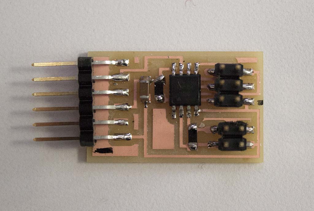
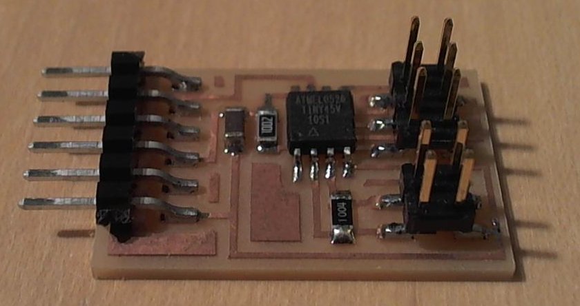
I started this week out by making a copy of Neil’s step response board to act as a control for future experiments + to get some extra practice with the milling, stuffing, compiling, etc. process. At this point I understand the process of compiling my code into a .hex file, programming the fuses for a given resonator, and uploading my code through terminal.
The new step was getting the associated python python script to run on my computer. The first step was getting Python to run through cmd – it isn’t automatically added to the DOS path by default. Before I realized this, I was getting this error message:
'python' is not recognized as an internal or external command,
operable program or batch file.
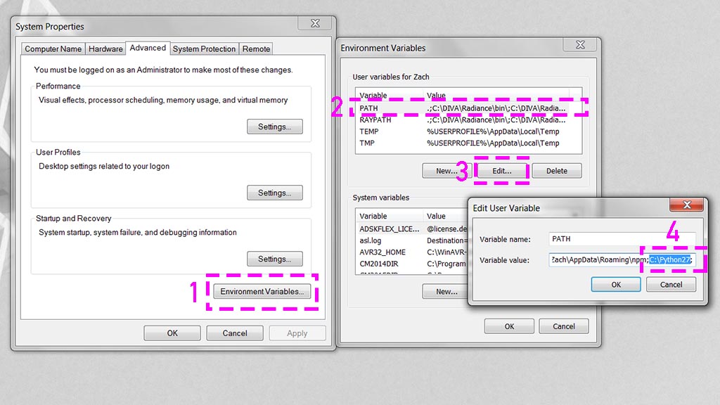
Luckily, NovySan was around to help me figure this process out. Navigate to Control Panel > System > Advanced System Settings and follow the steps in the above image:
1. Under the Advanced tab, select Environment Variables,
2. Select the User variable Path and
3. Click Edit.
4. Add the file path for Python specific to your machine. In my case it was C:\Python27.
1. Under the Advanced tab, select Environment Variables,
2. Select the User variable Path and
3. Click Edit.
4. Add the file path for Python specific to your machine. In my case it was C:\Python27.
3. Click Edit.
4. Add the file path for Python specific to your machine. In my case it was C:\Python27.
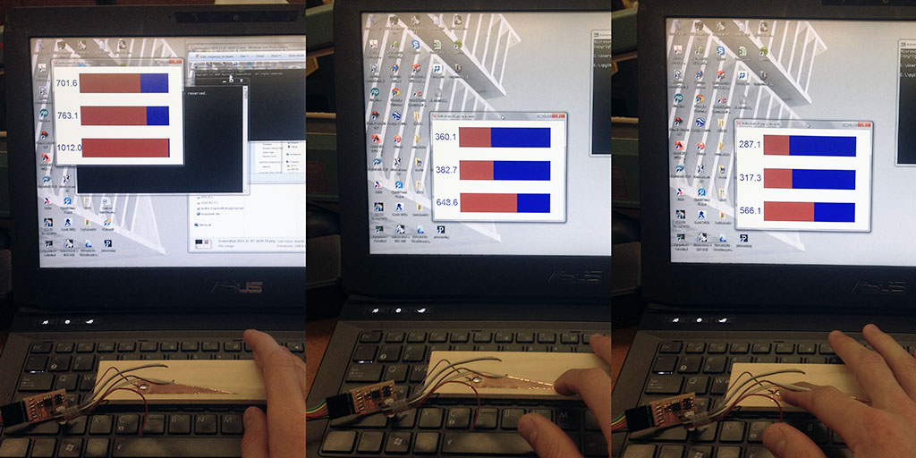
After that, it was easy to run the python script through cmd. Keep in mind that you have to specify the COM port that your device is attached to in addition to the .py file. Eg. I saved the script directly to my E: drive and so typed E:\>python hello.load.45.py COM13 into cmd to run the script. As an initial test, I cut a wedge-shaped piece of vinyl to see if I could measure a gradient of capacitance. It sort of worked, but I didn’t quite get the linear relationship between capacitance and surface area I was expecting….
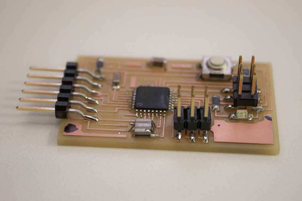
I realized that the microcontrollers I produced in week 6 weren’t 100% functional – In order to have a board that was functional + easy to prototype future assignments with, I decided to mill a fabduino. There are a number of tutorials and example boards to reference including:
http://academy.cba.mit.edu/content/tutorials/akf/hello_arduino.html
http://infosyncratic.nl/weblog/2013/04/25/more-on-fabduinos/
http://fab.cba.mit.edu/classes/4.140/people/amir/work/week8.html#1
There are a few different versions of the Fabduino floating around with a variety of microprocessors (ATmega168, ATmega328, ATmega328p…) resonators (8mhz internal, 8mhz external, 20mhz external…) and traces. I ended up milling and stuffing one with a ATmega328p + 20mhz resonator.
I had success setting fuses and programming in terminal (even if I didn’t completely understand all of the code) and so wanted to try the whole process using the Arduino IDE. Writing the bootloader turned out to be more involved than anticipated, but Amir’s tutorial was super helpful. Here is my process, borrowing heavily from Amir's instructions, but with the filepaths that worked for me + some shortcuts.
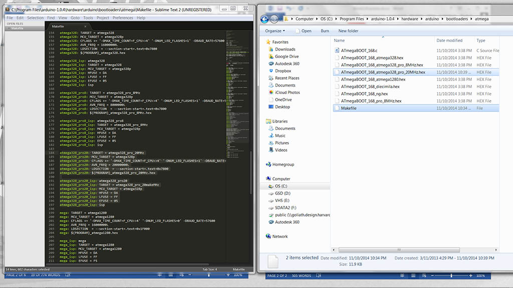
1. Add a new target for ATmega328p + 20MHz. Amir’s tutorial shows how to do this by editing the Makefile (mine was stored in C:\Program Files\arduino-1.0.4\hardware\arduino\bootloaders\atmega\...), but you can also just add this .hex file and replace the existing Makefile with this one. I tried editing my existing file and making new .hex using both Command Prompt + Cygwin, but kept getting errors when compiling my .hex file. The copy/replace technique seemed to work fine.
2. Create a new board definition. In your sketchbook folder (C:\Users\Zach\Documents\Arduino\hardware\ATmega328 in my case – you can find yours in Arduino under Preferences>>Sketchbook Location), create a new folder hardware if it doesn’t already exist. Within hardware make a folder called ATmega328p and place this boards.txt file in it.
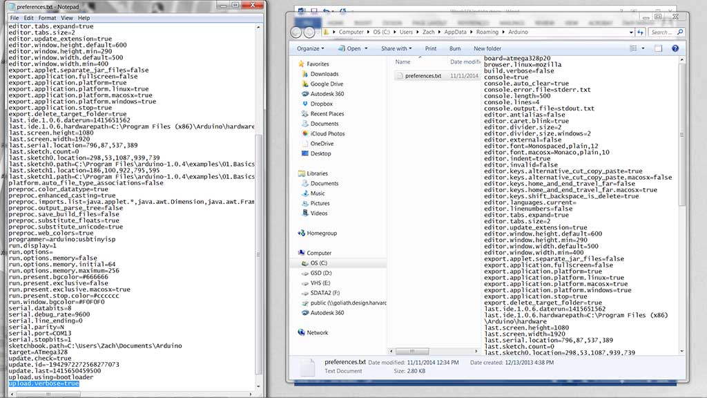
3. In the preferences.txt file, change upload.verbose=false to upload.verbose=true. You can locate a local copy of this file by opening Arduino, then nagivating to File>>Preferences. The location of this file is shown at the bottom of the preferences dialog box. Make sure Arduino is closed when editing, otherwise the changes won’t take effect. Changing this allows you to see “behind the scenes” when uploading code.
4. Now you’re ready to burn the bootloader. The correct board to select is ATmega328P, 5v, 20MHz external ceramic resonator. Be sure to also select the appropriate programmer + serial port, then select “Burn Bootloader”.
I've so far been able to successfully program my board through the Arduino IDE to read digital + analog communication via the serial monitor. No luck getting the LED to blink, but I will troubleshoot this for next week.