When Nadya and James came over for section on Friday, they very
helpfully allowed us to try out their working boards, to make
sure that the gestalt
system could funtion without issues on
our computers. This way, we also got to see what a final electronics
setup would look like. One issue that many people had to adjust
was that new USB devices do not automatically appear as the
/dev/ttyUSB0 device, and so that has to be changed in
the gestalt software. In any case, it was very easy to plug in
their system and get it to work.
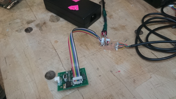
That day, we downloaded the board designs from Ilon's repository and made the board for the Fabnet adapter:

The outline cutting had some glitches, but in the end that didn't affect the board integrity. After we got some 600ohm resistors from Nadya, soldering was straightforward. We got a power supply from the Architecture fab shop; as it had no flex cable to connect it to the wall, we found one in the Stata loading docks:

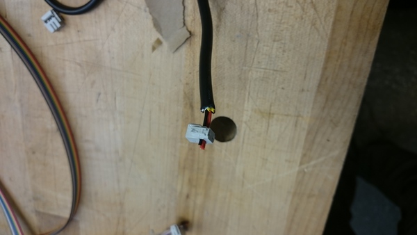
The power supply had 5 wires in it; 2 12V yellow wires, 2 5V red wires, and 1 ground wire. Used to the convention that 5V is standard power voltage and because the power supply in the example fabnet boards had red wires, we made the 2x2 header connect to the red 5V wires, which turned out to be a big mistake.
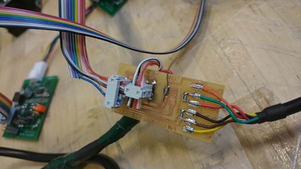
When we convened on saturday to get the system working, there were a number of problems. First, the power supply refused to provide power. We noticed that the power supply had its light turn off when it was plugged in. By repeatedly removing pieces of the system, we realized that it turned off when it connected to the 2x2 power pins on the fabnet board. With a voltmeter we figured out that the connector was being shorted whenever it was connected to the header pins; the problem arose because the power supply wires were too thick. We took off the connector and snipped off one of the pins in the connector that was shorting two of the wires, and this solved that problem. (Notice the glue -- we didn't have any more 2x2 connectors at this point ^_^)
Now the boards would power on, and the IO light would blink on the gestalt board, but when the gestalt software would prompt to identify a node, the message from the board did not seem to get through to the PC. Tim Fallon opened up the eagle schematics and began systematically figuring out which pins were supposed to be connected where. We found that there were intermittent shorts across the RS485-A and RS485-B wires based on physical movement, and occasional high-impedance (~200 Ohm) connecttions across the RS485 wires to the gestalt. We reflowed many of the solder joints and redid the header; this largely solved the problem.
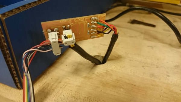
However, there were still intermittent connection problems. By investigating the gestalt board schematic, we figured out that the gestalt board was powering the microcontroller by passing power through an (enormous !!) regulator which had a minimum input voltage of 7V. Thus, the 5V power supply was causing power to be delivered unreliably to the microcontroller. Thus we redid the power supply connection again, this time using the yellow wires.
(We had to borrow some 4-pin plastic headers from the IDC since we ran out; thanks guys!) Finally, after plugging all this in, everything worked!
We had a lot of fun making the steppers move back and forth really fast to make printer sounds :-) Making stuff is fun!
