NRF24L01
The nRF24L01 is a highly integrated, ultra low power (ULP) 2Mbps RF transceiver IC for the 2.4GHz ISM (Industrial, Scientific and Medical) band. With peak RX/TX currents lower than 14mA, a sub μA power down mode, advanced power management, and a 1.9 to 3.6V (5V is okay) supply range, the nRF24L01 provides a true ULP solution enabling months to years of battery lifetime when running on coin cells or AA/AAA batteries .
There are different types of network that you can create with NRF24, you can find them here http://playground.arduino.cc/InterfacingWithHardware/Nrf24L01
This post will only cover wiring, sending and receiving.
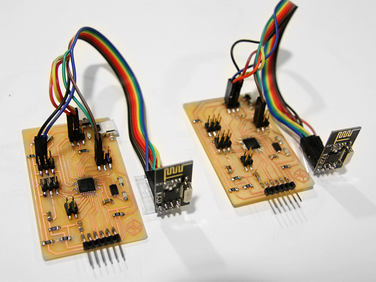
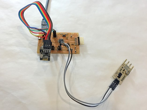
Here is how to wire the NRF24L01 to your atmel chip, in my case I made my own with ATmega328p, which is the same as the Arduino UNO.
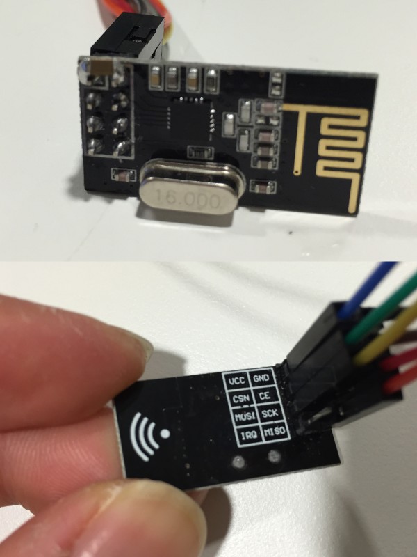
This table shows how you would map your pins
| NRF24L01 | ATmega328p | ATtiny25/45/85 [0] | ATtiny44/84 [1] |
|---|---|---|---|
| GND | GND | pin 4 | pin 14 |
| VCC | 3.3V (5V is okay) | pin 8 | pin 1 |
| CE | digIO 7 | pin 2 | pin 12 |
| CSN | digIO 8 | pin 3 | pin 11 |
| SCK | digIO 13 | pin 7 | pin 9 |
| MOSI | digIO 11 | pin 6 | pin 7 |
| MISO | digIO 12 | pin 5 | pin 8 |
| IRQ | – | – | – |
I used this site as my guide to program NRF24L01 with RF24
http://maniacbug.wordpress.com/2011/11/02/getting-started-rf24/
Note: The Chip can work under 5V, but 3V is recommended.
You can wire up using jumper wires, they are good for testing the wiring, not so reliable for final projects.
Running the example Code
Here is the RF24 library for the Arduino IDE https://github.com/TMRh20/RF24, it also covers duplex and many other examples. Don't know how to load the external library? Please Read This
We are running this file
libraries/RF24-master/examples/GettingStarted_CallResponse/GettingStarted_CallResponse.ino
or in Arduino IDE file menu:
File > Example > RF24-master …
Once I upload the sketch to Arduinos/Fab-durio/ATmega328p/ATmega44, I get the following serial data from the Arduino IDE’s Serial Monitor (the magnify glass icon on top right)
If you did not get the below message, you might want to check your wiring, this is NRF24L01 talking back to the Arduino/Fab-durio/ATmega328p.
Important Note: make sure your serial bud rate is 57600
RF24/examples/GettingStarted/
ROLE: Pong back
STATUS	= 0x0e RX_DR=0 TX_DS=0 MAX_RT=0 RX_P_NO=7 TX_FULL=0
RX_ADDR_P0-1	= 0xf0f0f0f0d2 0xf0f0f0f0e1
RX_ADDR_P2-5	= 0xc3 0xc4 0xc5 0xc6
TX_ADDR	= 0xf0f0f0f0d2
RX_PW_P0-6	= 0x08 0x08 0x00 0x00 0x00 0x00
EN_AA	= 0x3f
EN_RXADDR	= 0x03
RF_CH	= 0x4c
RF_SETUP	= 0x07
CONFIG	= 0x0f
DYNPD/FEATURE	= 0x00 0x00
Data Rate	= 1MBPS
Model	= nRF24L01
CRC Length	= 16 bits
PA Power	= PA_HIGH
If you have 2 nRF24 running you can set the role for individual nRF24, sending or reciving.
For this example, you can press T for transmit and R fro receiving.
You can also set the pipe address, (the channel that the device will be on), by changing the following.
byte addresses[][6] = {"8Node","8Node"};
Modifing the RF24 GettingStarted_CallResponse example
To understand the code, I slowly remove and put back parts of the code to understand how it works. Since this example contains both sending and receiving codes, I decided to isolate them to do only sending or receiving on individual nRF24 right after powering them up. (I took out the sending and receiving selection)
Creating a sending only Nrf24L01 by taking out the receiver part of the code
#include
#include "nRF24L01.h"
#include "RF24.h"
#include "printf.h"

// Hardware configuration: Set up nRF24L01 radio on SPI bus plus pins 7 & 8
RF24 radio(7,8);

int sensorPin = A1;    // select the input pin for the potentiometer

byte sensorValue;
byte seninbyte;
                                                                           // Topology
byte addresses[][6] = {"8Node","8Node"};              // Radio pipe addresses for the 2 nodes to communicate.

// Role management: Set up role.  This sketch uses the same software for all the nodes
// in this system.  Doing so greatly simplifies testing.
typedef enum { role_ping_out = 1, role_pong_back } role_e;                 // The various roles supported by this sketch
const char* role_friendly_name[] = { "invalid", "Ping out", "Pong back"};  // The debug-friendly names of those roles
role_e role = role_pong_back;                                              // The role of the current running sketch

byte counter = 1;                                                          // A single byte to keep track of the data being sent back and forth


void setup(){

  Serial.begin(57600);
  printf_begin();
  printf("\n\rRF24/examples/GettingStarted/\n\r");
  printf("ROLE: %s\n\r",role_friendly_name[role]);
  printf("*** PRESS 'T' to begin transmitting to the other node\n\r");

  // Setup and configure radio

  radio.begin();
  radio.setAutoAck(1);                    // Ensure autoACK is enabled
  radio.enableAckPayload();               // Allow optional ack payloads
  radio.setRetries(0,15);                 // Smallest time between retries, max no. of retries
  radio.setPayloadSize(1);                // Here we are sending 1-byte payloads to test the call-response speed
  radio.openWritingPipe(addresses[1]);        // Both radios listen on the same pipes by default, and switch when writing
  radio.openReadingPipe(1,addresses[0]);      // Open a reading pipe on address 0, pipe 1
  radio.startListening();                 // Start listening
  radio.powerUp();
  radio.printDetails();                   // Dump the configuration of the rf unit for debugging


  role=role_ping_out;

}

void loop(void) {

  sensorValue =    map (analogRead(sensorPin), 500, 988, 0, 180); // wind sensor
  if (sensorValue>-1 && sensorValue < 181){
    seninbyte=sensorValue;
  }


/****************** Ping Out Role ***************************/


  if (role == role_ping_out){                               // Radio is in ping mode

    byte gotByte;                                           // Initialize a variable for the incoming response

    radio.stopListening();                                  // First, stop listening so we can talk.
    printf("Now sending %d as payload\n\r",seninbyte);          // Use a simple byte counter as payload
    unsigned long time = micros();                          // Record the current microsecond count

    if ( radio.write(&seninbyte,1  ) ){                         // Send the counter variable to the other radio
    //if ( radio.write(&counter,sizeof(counter)) ){                         // Send the counter variable to the other radio
        if(!radio.available()){                             // If nothing in the buffer, we got an ack but it is blank
            //printf("Got blank response. round-trip delay: %lu microseconds\n\r",micros()-time);
        }else{
            while(radio.available() ){                      // If an ack with payload was received
                radio.read( &gotByte, 1 );                  // Read it, and display the response time
                printf("Got response %d, round-trip delay: %lu microseconds\n\r",gotByte,micros()-time);

                //counter++;                                  // Increment the counter variable
            }
        }

    }else{        printf("Sending failed.\n\r"); }          // If no ack response, sending failed

    delay(100);  // Try again later
  }


}
Creating a receiving only Nrf24L01
#include
#include "nRF24L01.h"
#include "RF24.h"
#include "printf.h"
#include


Servo myservo;
int pos = 0;

// Hardware configuration: Set up nRF24L01 radio on SPI bus plus pins 7 & 8
RF24 radio(7,8);
                                                                           // Topology
byte addresses[][6] = {"8Node","8Node"};              // Radio pipe addresses for the 2 nodes to communicate.

// Role management: Set up role.  This sketch uses the same software for all the nodes
// in this system.  Doing so greatly simplifies testing.
typedef enum { role_ping_out = 1, role_pong_back } role_e;                 // The various roles supported by this sketch
const char* role_friendly_name[] = { "invalid", "Ping out", "Pong back"};  // The debug-friendly names of those roles
role_e role = role_pong_back;                                              // The role of the current running sketch

byte counter = 1;                                                          // A single byte to keep track of the data being sent back and forth


void setup(){

  Serial.begin(57600);
  myservo.attach(A1);  // attaches the servo on pin 9 to the servo object

  printf_begin();
  printf("\n\rRF24/examples/GettingStarted/\n\r");
  printf("ROLE: %s\n\r",role_friendly_name[role]);
  printf("*** PRESS 'T' to begin transmitting to the other node\n\r");

  // Setup and configure radio

  radio.begin();
  radio.setAutoAck(1);                    // Ensure autoACK is enabled
  radio.enableAckPayload();               // Allow optional ack payloads
  radio.setRetries(0,15);                 // Smallest time between retries, max no. of retries
  radio.setPayloadSize(1);                // Here we are sending 1-byte payloads to test the call-response speed
  radio.openWritingPipe(addresses[1]);        // Both radios listen on the same pipes by default, and switch when writing
  radio.openReadingPipe(1,addresses[0]);      // Open a reading pipe on address 0, pipe 1
  radio.startListening();                 // Start listening
  radio.powerUp();
  radio.printDetails();                   // Dump the configuration of the rf unit for debugging


  role=role_pong_back;


}

void loop(void) {


/****************** Pong Back Role ***************************/

  if ( role == role_pong_back ) {
    byte pipeNo, gotByte;                          // Declare variables for the pipe and the byte received
    while( radio.available(&pipeNo)){              // Read all available payloads
      radio.read( &gotByte, 1 );
                                                   // Since this is a call-response. Respond directly with an ack payload.
                                                   // Ack payloads are much more efficient than switching to transmit mode to respond to a call
      // turing this off, no feedback
      //radio.writeAckPayload(pipeNo,&gotByte, 1 );  // This can be commented out to send empty payloads.
      //printf("Sent response %d \n\r", gotByte);
      printf("I am getting %d \n\r", gotByte);

      if (gotByte>0){
        myservo.write(gotByte);
      }
              delay(100);

   }
 }


}
Download my version of RF-24
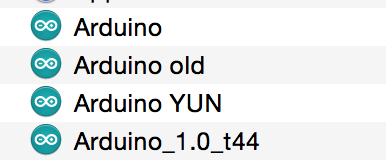
Get Serial Data with 2 USB Ports on One Computer
Tip: Use 2 Arduino IDEs to get 2 serial data with FTDI, so you don’t need a 2nd computer. All you need to do is duplicate the Arduino program in your application folder on your mac.
Here I have the code running with the wind sensor. Wind sensor just measures the current drop between the 2 wires, so whenever I touch the tip of the wire, the voltage drops.
Adding some output devices
Testing the wiring and software with a servo and a wind sensor.
Sender
The sender contains an analog wind sensor, that I purchased from here. http://moderndevice.com/product/wind-sensor/
Receiver
The receiver end has a servo, getting the position data from the sender.
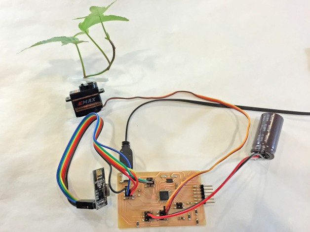
Putting it all together
I imaging you could place the “sender” outdoor to sense the wind and reproduce the environment with the servo indoor.
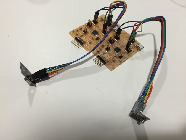
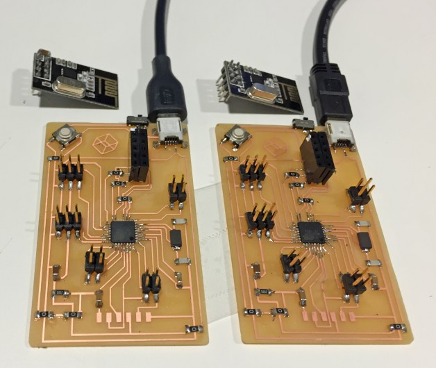
Integrate with DanDurino / Making a direct plug
To save space and wiring, I decided to make a new board without ISP header and pins for Nrf24L01.
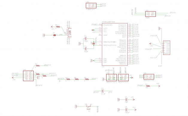
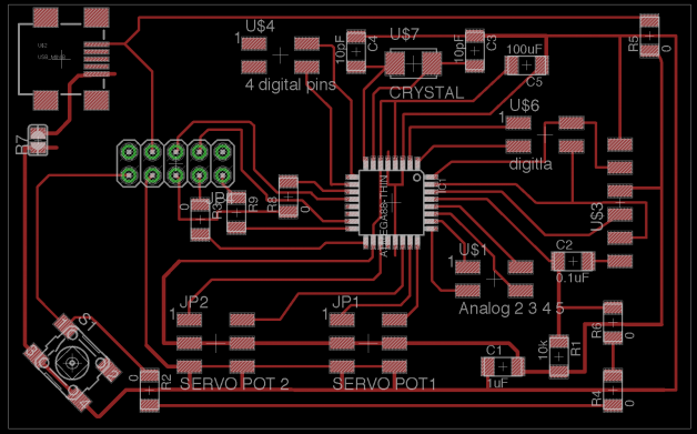
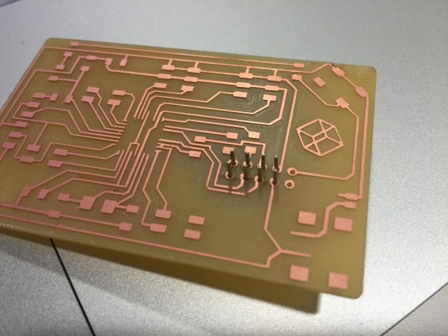
I removed the IPS pins so I had to make my own custom IPS pins that will fit with the Nrf24L01. I included the reset pin on first column.
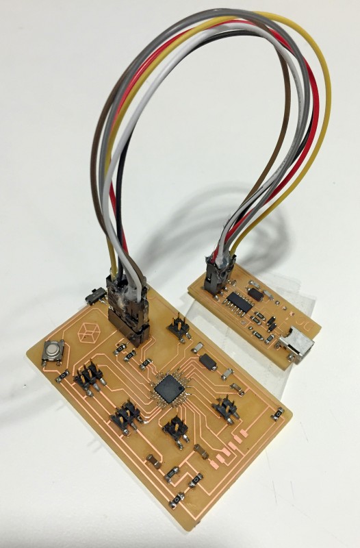
The special pins works as ISP or Nrf24L01, with a custom made jumper cable, I can burn bootloader onto my board, then use it as jack for the nRF24.
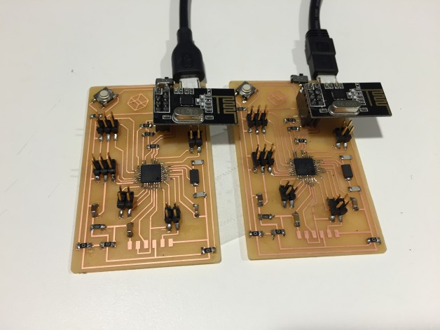
After burning the boot loader successfully, I was able to run exactly the same sending and receiving sketches. These will be the perfect boards for my final project.