In-System Programming Board
01. Electronics Production
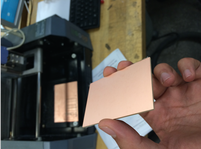
The goal of this week is to create a In-System programming Board from scratch using etching/machining to made the electronic circuit and then populate the board with key components for the programmer. In my case, I used a machining technique with two different types of tools: a 1/64 head for cutting the circuits, and a 1/32 head for actually cutting the board. Two designs are suggested: the hello.ISP.44 card and the integrated USB. I first worked on the first version and then printed the integrated USB but did not populate it. The first step is to find a new board:
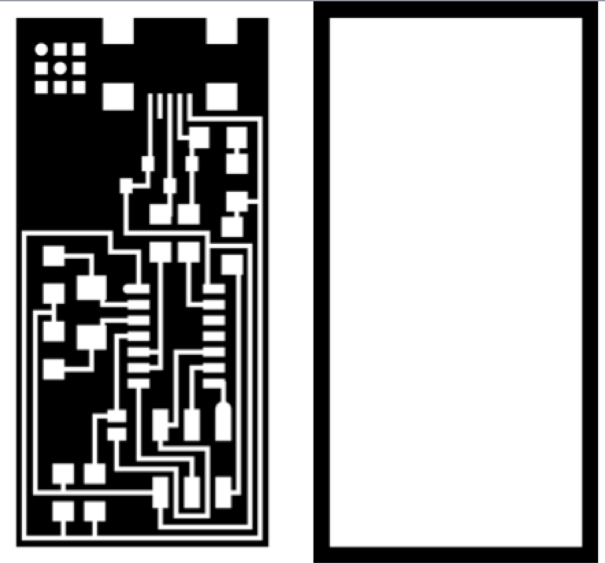
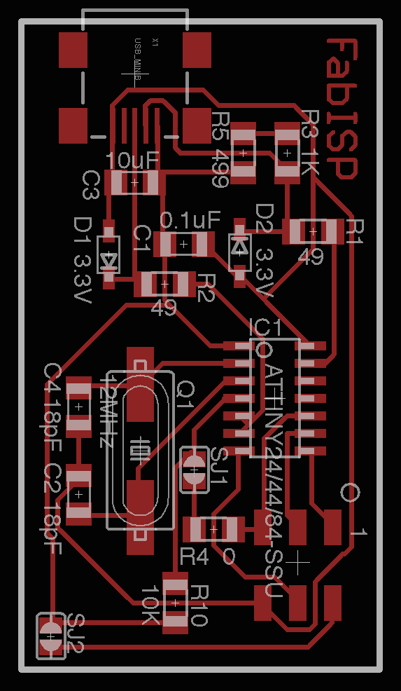
Now, we will first "machine" the board to create the circuit, with a 1/32 head. Then, we will use the 1/64 head to cut it. For both of those operations, we use fab module, selecting the png format, uploading the two different png files design for the (left for machining, right for cutting), we select the Roland mill tool (.rml), with a process of PCB traces 1/64 or PCB outline 1/32 for cutting.
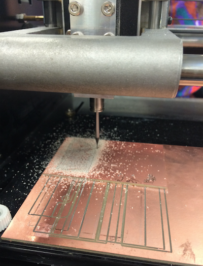
The output machine is the MDX-20, with 4mm/s speed, job height 1mm, and initial position 2mm (x) 2mm (y) and 20mm (z). Be careful, I changed the z position and it carved the board too deep. Then before pressing "move to xmin.ymin", press "calculate". The cut depth should be 0.12mm for the traces (tool diameter: 0.4, number of offsets 4, offset overlap 50, path error 1.1, image threshold 0.5). Then, we shoud press the View button on the MDX-20 and now we can "move to xmin-ymin". Now comes the operation of changing the head and adjusting the head to cut the board. This operation is really not difficult at all but I had a lot of troubles and reauired me a lot of iterations simply because I was usimg a 1/32 head instead of a 1/64. The different steps before launching the print are: fixturing on a sacrificial layer with double sided tape, zeroing. One we have done the traces, we can do the cutout (and not the other way).
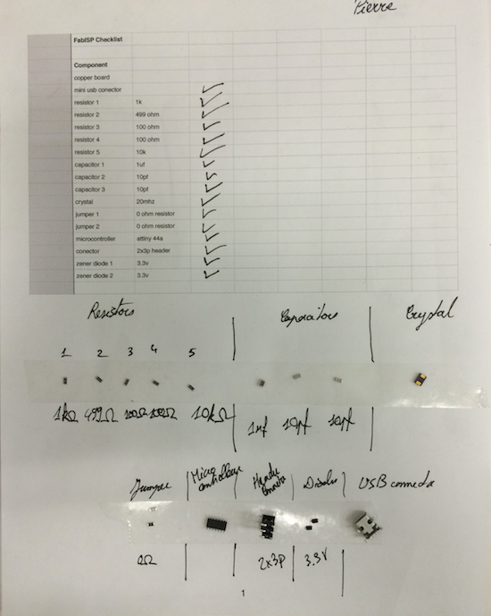
Now, while printing, as it is not a laser cutter and you can move and don't have to watch the whole process, you shoudl start selecting the different components required for populating the board: resistors, capacitors, mini USB connector, crystal, microcontroller, connector, diodes. It takes a while to find all of the right companents and a good approach is to tape then on a sheet once we have them while labelling them. Then, once we have all of the components, we can start soldering. The method is always to start by the smallest and shortest components in the middle and then build the taller ones. A good idea is also to start by difficult components such as the USB connector because if we mess up, them we can always print quickly a new board and we don't lose too much time. The tricky components are the diodes that have a direction and the microcontrolleur that also have a direction. Otherwise, we should use the classic soldering technique, making sure to touch the two parts with the iron to heat them, starting by putting a sphere or solder on a first patch, placing the component on it to fix it, then do the other patch, and come back on the first patch to finish a nice solder. It must be shiny and smooth solder.
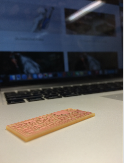
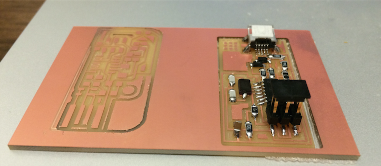
At the end, we have a populated board like seen on the picture. On the left is the second design of the integrated USB ISP that is not populated yet.
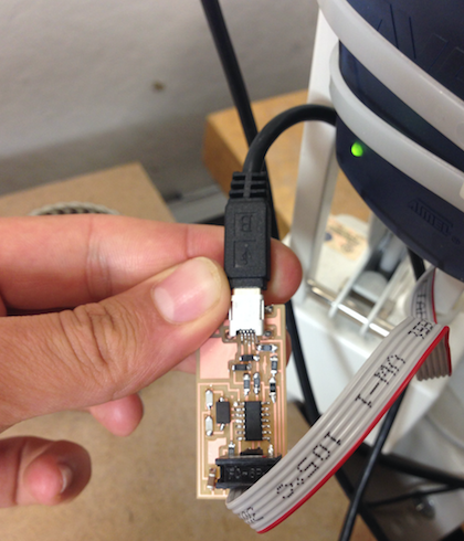
Now, we want to program our ISP through our computer. Everything is well explained here, but I will try to briefly summarize it, here. We need to plug the USB through the USB head (to power it) and trhough the 6 pin header, to talk with it. The 6 pin header is linked to an AVR.
First, we need to download the necessary software for AVR Programming. We first follow this tutorial, starting at "Mac Setup - paths" and stoping before "Option1. AvrMacPack". Then we download and Install Crosspack AVR, and then we Get Make (via Xcode)
Second, we need to download the firmware and to unzip it on the desktop. And with the Terminal, move into that folder. Then we power the FabISP board, with the micro-USB and the other power source. And then, we should type the following commands: make clean, make hex, sudo make fuse, sudo make program, and we are all set.
Finally, to make sure the our computer see the USB, we go to About this Mac, System Report, USB, and we should be able to see the FabISP. The last step is to move the jumpers to make the programmee become a programmer.