Make Program for Hello World
07. Embedded Programming
The goal of this week is to be able to program the ATtiny board that we made. There are multiple ways to program the board with different options. I tried to synthetize the different ways and different workflows, here:

Some useful link to better understand the different things and miscellaneous comments:
- There are tons of AVR tutorials online by googling
- What is GCC here
- AVRlibc: is the way to teach GCC how to speak to AVR
- Bruning Bootloader with Arduino is equivalet to flashing fuses
- Tools: Processor Attiny 44a
- Clock: 20 MHz
- In Programmer can use USBtiny if we want to use the FabISP or we choose the AVR ISP if we want to use the AVR programmer

It is where I first encountered some issues: I got the following error message:
verification error first mismatch at byte 0x0000 0x0c = 0xff
I googled the issue and people onine were suggesting that I needed to clear the lock bit to change the fuse (the lfuse) from the safemode. The code with used to troubleshoot was
avrdude -p t44 -c avrisp2 -P usb -U lfuse:r:-:h -U hfuse:r:-:h -U efuse:r:-:h -U lock:r:-:h
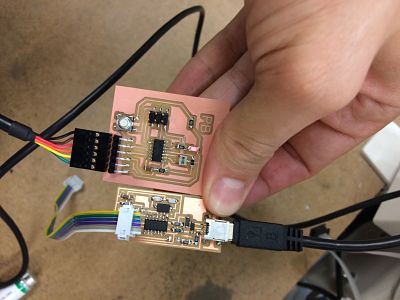
Then the two boards ( the two targeted board, one with a red LED and one with a blue LED) were working fine: they were bootloaded correctly. I started using the blue LED and tried to send the following simple program in Arduino (but it is actually C) to blink the LED:
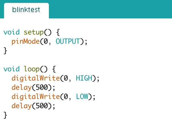
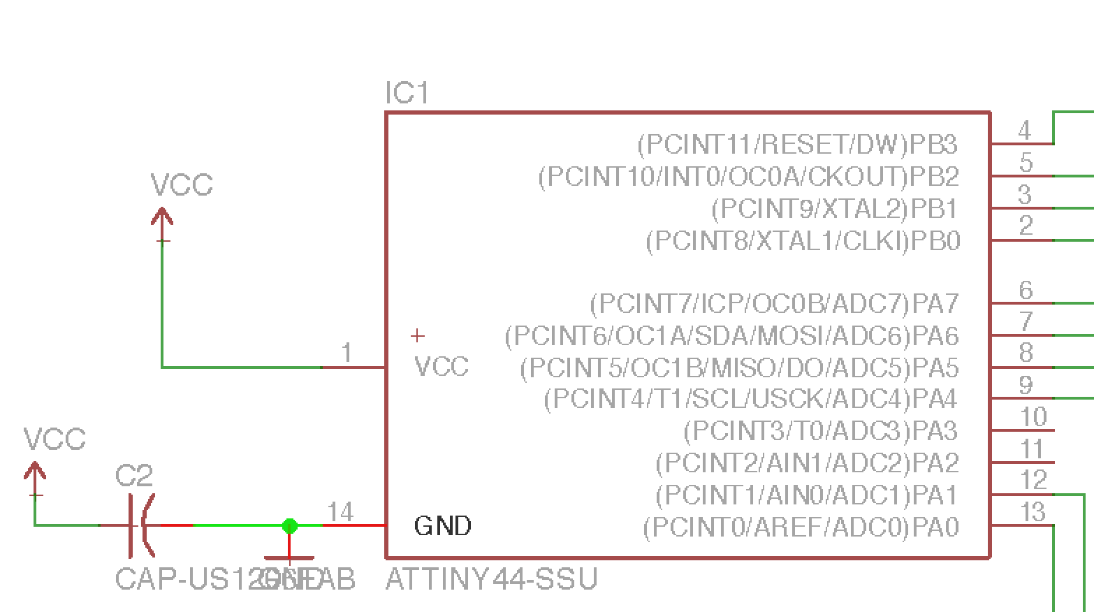
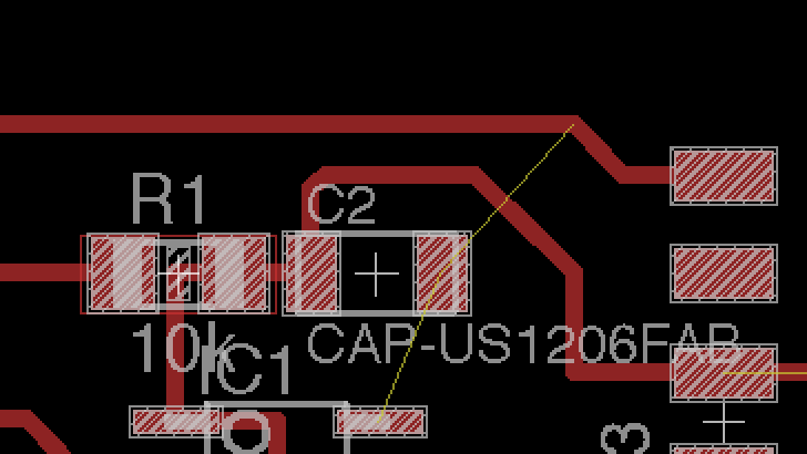
The issue is that the LED was not blinking. By just sending a program with only a HIGH signal on the LED, I figured out that there was an hardware issue. It was actually the ground of the microcontroller that was not grounded:
I thus added a jumper resistor on the two boards to fill the gap.
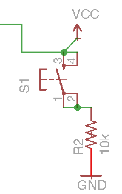
And then it worked to make the LED blink. The red LED board actually did not work and it is due to a bad schematics and traces. I used the blue LED for the following stages. The other challenge was then to combine the LED and the button to actually activate the LED. When I tried to send the following script, nothing happened.

It was actually because the button in schematics was not well positionned and the button pin signal of the microcontroller was constantly receiving the VCC that was aimed at the VCC of the microcontroller. I should have put the button before it.
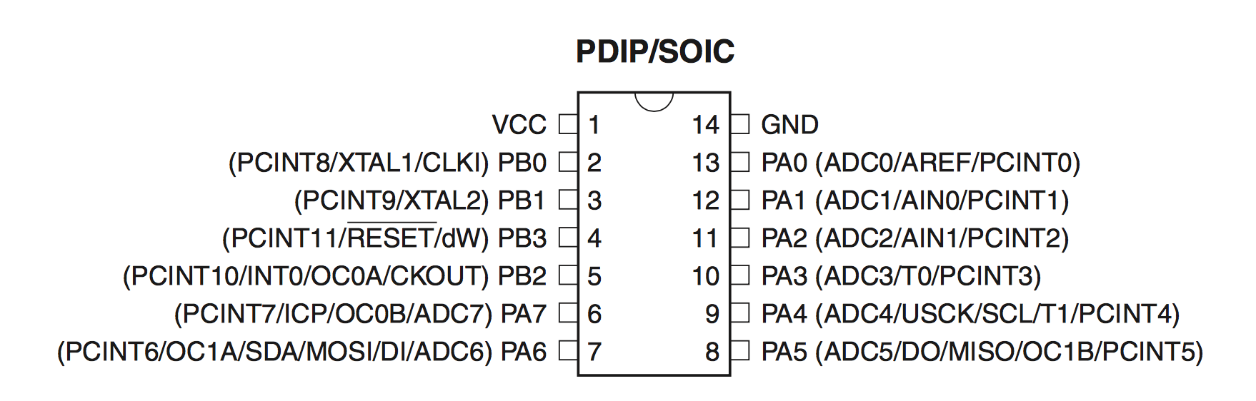
To troubleshoot this issue, I actually tried to reach for a non used pin of the controller. I soldered an external jumper with a wire and attached it to a free pin. I used the data sheet to know how to code in Arduino.
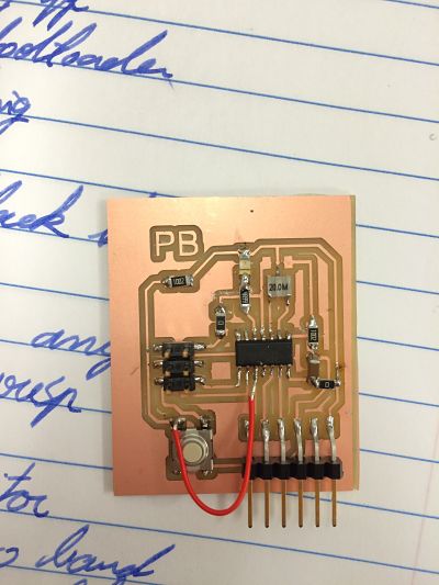
The final version of the board working was thus the following. We can see the added jumper to link the ground of the pin to the ground and also the new link between the button and another pin.
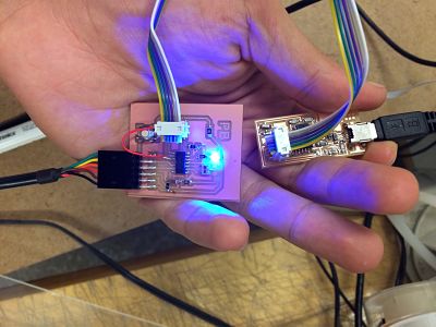
And it worked:
I then downloaded the make program and run the following instructions:
make -f hello.ftdi.44.echo.c.make
make -f hello.ftdi.44.echo.c.make program-avrisp2 (If we want to use the AVR ISP)
make -f hello.ftdi.44.echo.c.make program-usbtiny (if we want to use the FabISP)
We can then go to Arduino IDE and select Tools/Serial Monitor and then type and communicate with the board:
