Smart Bike Seat
13. Final Project
The summary of the project can be found here:
This project was born after a couple of observations:
- Boston winters are cold
- Boston winters are dark
- My bike seat is broken
- I often forget to turn off my bike light
- My bike lights get often stolen
- Turn the lights on and off automatically when it is dark enough and when someone is seated on the bike seat
- Turn the a seat heater on and off automatically when it is cold enough and when someone is seated on the bike seat
- Have the bike lights intergrate to the bike to avoid been stolen

I finally thought that I would design from scratch my own bike seat and try to integrate it to my current bike. The following sections describe the system overall and the detailed process of the different steps (bike seat support creation, electronics design, electronics production, 3D printing...). But before starting I wanted to send a huge thank you to Dan Chen, who really helped me a lot !
a. System
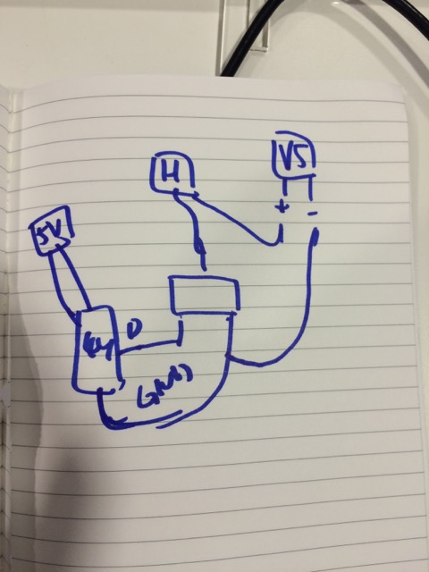
A first sketch was helpful to visualize what I wanted to do, with the different components.
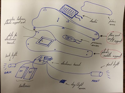
- A hard layer made to support the weight of the rider (casted in a MDF mold + OOMOO soft mold) and be the interface with the bike
- A soft layer used to be comfortable for the rider (casted in OOMOO with a MDF mold)
- A Pressure sensor integrated in the bike seat (capacitive (homemade), resisitive (homemade or bought like FSR) or push button)
- An electronic board integrated with the seat, with a microcontroller (Attiny44), a light sensor (phototransistor), temperature sensor (Resistance Temperature Sensor or RTD)to detect night/day and cold/warm weathers
- A seat heater (bought)
- A final layer in fabric to protect the hardware and software
- Bike light supports integrated with the bike (3D printed)
- LED to provide light
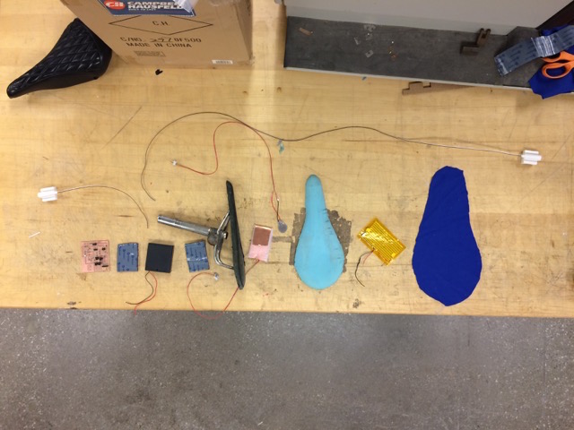
On the previous picture, we can see the different components before integration. From left to right: LED and LED support for the rear side, electronic board, Velcro to attach the board to the seat, batteries, cast seat with metallic rails as interface, pressure snensors (capacitive Tx/Rx and homemade resistive sensor), comfortable layer, bike seat heater, fabric layer and front light with light holder. The total cost of the board was approximatively $100, and could be splited between the different components:
- The input devices, < $5: phototransistor ($0.38), RTD ($3.66) and pressure sensor (free, homemade)
- The output devices, <$5: heater ($4), LEDs (<$1)
- Molding and Casting < $10: Urethane rubber or OOMOO ($25 a whole set, I used 10%) and urethane plastic ($25 a whole set, I used 10%)
- 3D printing: negligeable
- Electronics Design and production: negligeable
- External electronics $80:recheargeable batteries ($25), FTDI cable ($7), Compatible Atmel AVRI ISP ($43)
- Molding and casting: design in Rhino + Mastercam, MDF 3D milling with the Shopbot and the Onrsud machines, casting with urethane rubber and urethane plastic
- 3D printing: design in Antimony and Rhino, printing with the MakerBot
- Electronics design and production: design in Eagle, production by traces milling with Modela MDX-20 and fab module, stuffing with soldering iron (surafec mounted)
- Embedded programming: in C with Arduino IDE environment
- Sewing the additional surface layer
The following sections goe in more details about the different processes involved in this project
b. Bike seat production
I wanted and needed to replace my old bike seat that was falling apart and create a new seat.
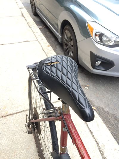

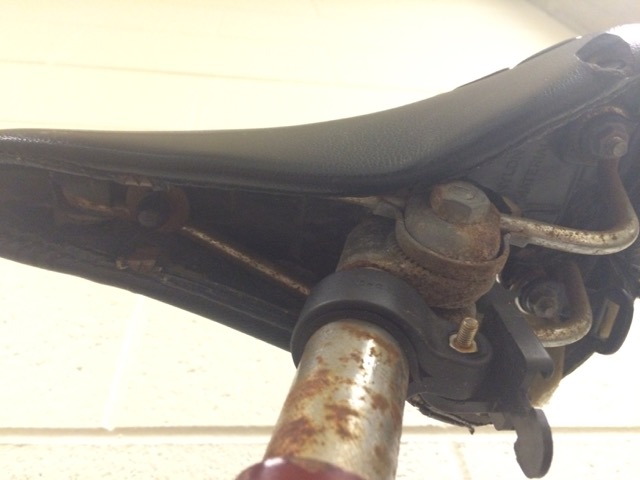
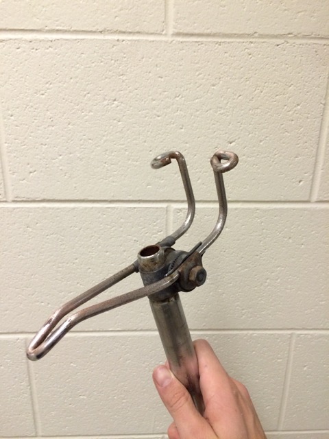
The first challenge of this part was to produce a comfortable and useable seat that was also a good interface with the bike. I studied some existing design and as well as my former interface and I saw that I wanted to reuse the metallic rails that were still rusted but in good conditions:

The different options for interface were:
- Welding a metallic seat support to the metallic bars
- Screw a MDF or wooden hard support to the metallic bars
- Bolt a composite layer to the metallic bars
- Cast a support of platic urethane to the metallic bars
I thus decided to produce two layers: one comfortable and one hard that would be the interface with the bike. The description of the comfortable layer is describe in more details in the Molding and Casting page. The process was basically to design the a mold in Rhino using an existing 3D model in Solidworks of a bike seat that was adapted to my bike, and after having milled the mold in MDF, I cast the rubber urethane (or OOMOO) in the mold and I had the comfortable layer:
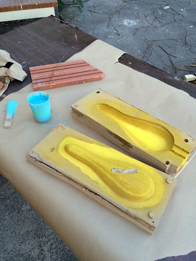
For the solid layer, I had to modify the original Rhino file used for the OOMOO layer and change the size to have a good 1 sided mold for the solid part. I would then incorporate the metallic bars to the mold on the top. I thus needed a resized bottom of the mold. I figured out that I could also simply resuse the OOMOO layer as a mold in addition to the MDF mold. The process was first to clean the metallic bars:
Then to prepare the urethane plastic liquid by mixing the two components (A and B) and then the color additive to have a black seat:


I then waited overnight that the mold was solid:

After decasting the solid layer I could see that it was a solid part and integrated well the metallic bars. It was not sure if it would be perfectly solid, especially since the metallic bars in the front did not have a lot of plastic covering them and thus sustaining the weight.
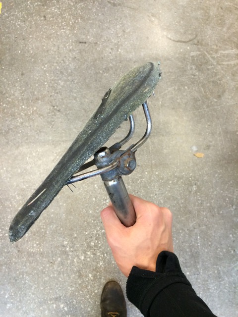

Finally, I had the 2 layers I wanted through this process.
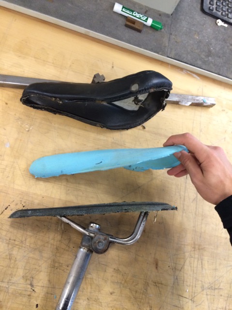
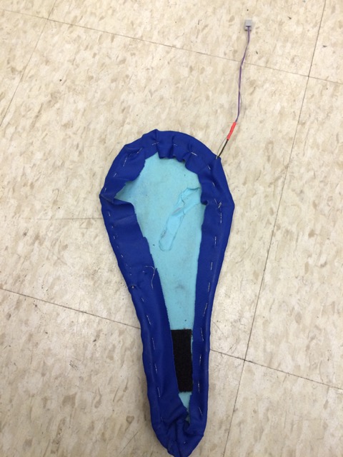
The last layer I added was a fabric layer (I replaced the lether layer seen in the picture) to cover the heater and the comfortable layer and give a better rendering. For that process, I saw the fabric layer to the OOMOO layer using a strong string.

The integrate OOMOO+heater+fabric layer is as follows:
c. Light holders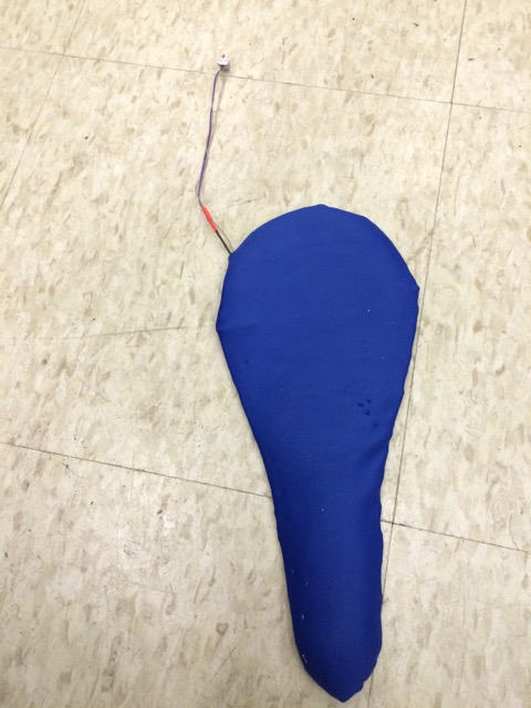
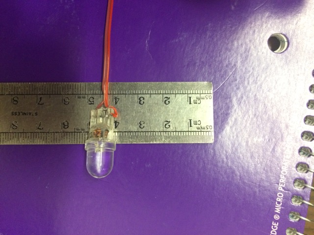
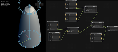
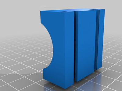
For the light holder, a requirement was that it could be directly integrated to the bike and would be difficult to remove to avoid being stolen. I thus chose to use a 3D printed holder. After having selected the LED I wanted to use (I actually changed the type of LED I used after), I took the right measurement to make the design using Antimony.
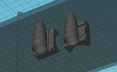
I then combined my own design with Antimony (see file here),

with an existing design of interface with a bike handle that I could find on Thingverse, here,
that would allow to use some permanent attachments to the bike to prevent the lights to be stolen. It was a combination of a simple and desired design
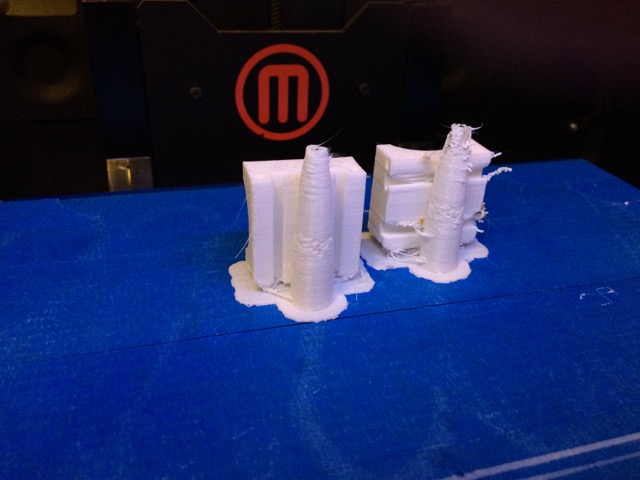
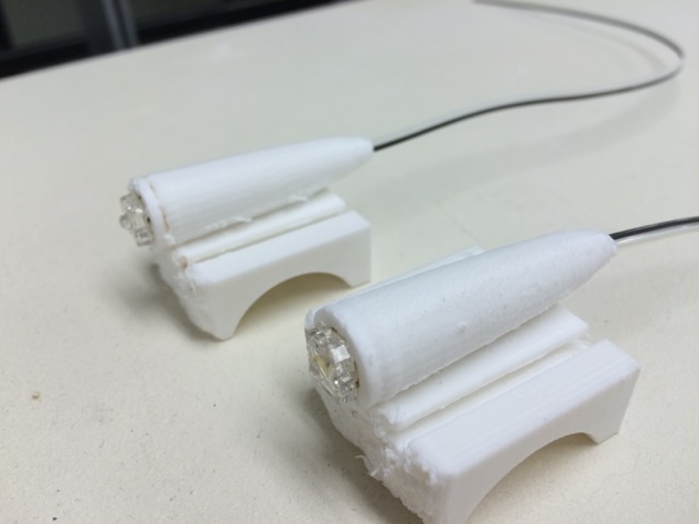
The 3D print was actually not perfectly successful for different reasons: first, Antimony did not have units and thus, the arbitrary units I chose were a little off, especially, in the design the thickness of the "tube" was to thin to be printed properly. Another reason was also that I used a configurated Makerbot software that was configurated for a 2-head printer and was planning in the default settings to print the support (needed for the interface with the handle that was "floating in the air") with the second head while the first head was printing the actual object. The result was thus the following:
Even though the design was not perfect, I tested it with the actual LED:
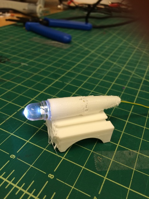

This design was successful. At the end I reprinted the light with a thicker tube but I still had the issue of the support (it is only after that I realised that I was off for the support), but in the same time I also decided to use different LED that I have that I found were brigher. At the end, the design was as follows
d. Electronics Design and Production
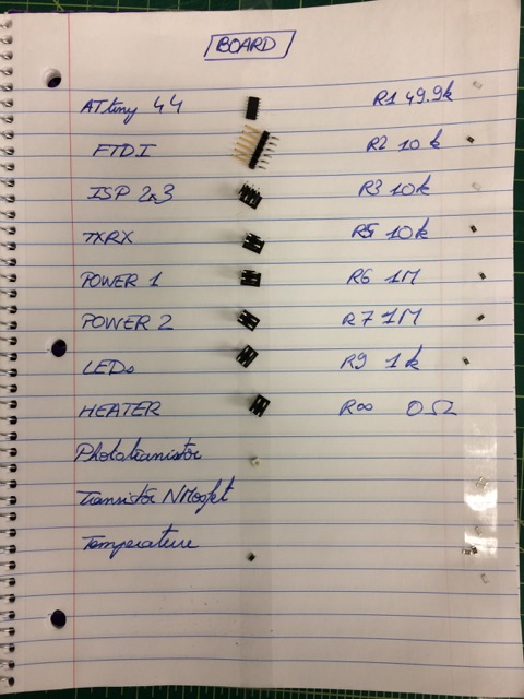
This part was probably the part of the project that asked the most iterations and where I maybe struggled the most. First, I tried to be inspired from the previous board designs. I used the input devices boards: temperature, light and step response, as well as the output like the DC motor one. To summarize, the different parts of the board were:
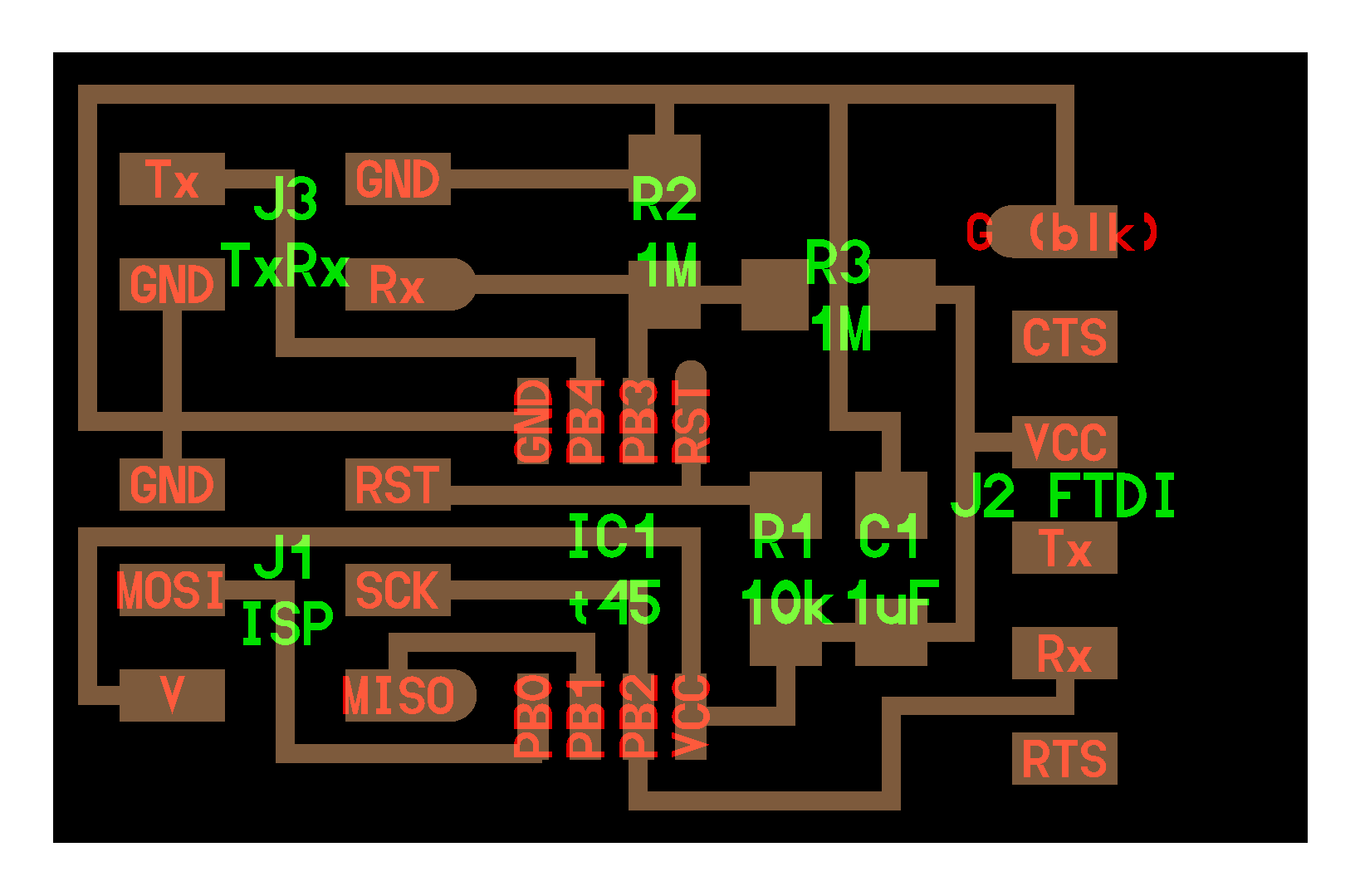
- Power supply: I first decided to have 2 different power supply: one for the heater with high amps that should be rechargeable easily, and one for the board that needed to be less powerful and with less capacity (Amph). I needed to filter the power supply with a 1uF capacitor and a 10k resistor as it is shown in the input device boards. I ended up using only one power supply that I would regulate with a voltage regulator, 5V-100mA for the board, and that I would not reglate for the heater, but that I would control with a N-MOSFET. The power supply was materialized on the board by a 2x2 header. For the heater batteries, I bought special 1.2V batteries with high capacity (2400mAh instead of 800mAh) because the heater was consuming a lot of power very quickly.
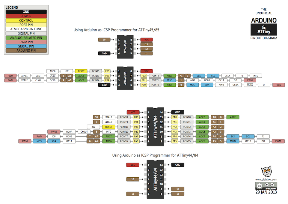
- Microcontroller: I wanted enough Analog to Digital pins to be able to sense the different metrics (light (1 pin), temperature (2 pins), transmit/receive (2 pins)) and also enough pins to control the LED (1 pin) and the heater (1 pin). I thus used the Attiny44 that actually had enough pins.
- Interface and Communication ports: I wanted to program the board and I thus used a 2X3 ISP port that I could plug to the AVR ISP, as well as a FTDI port to configurate the board and see what we were sensing. The mistake I made was to let the VCC coming in through the FTDI cable. It was thus conflicting at the voltage regulator level with the battery power and was overheated the regulator. One thing to remember is thus not to use the VCC from the FTDI cable when I powered it with external batteries.
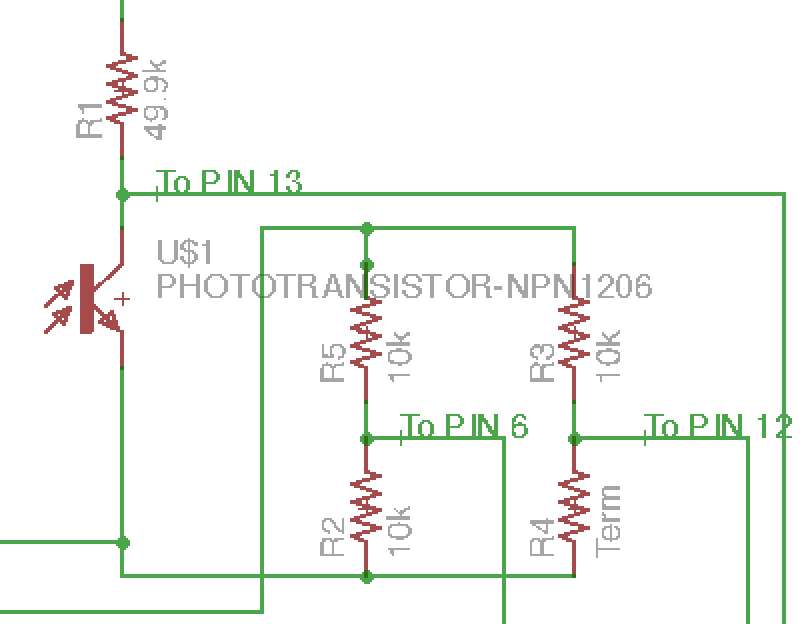
- Temperature sensor: I used a RTC sensor coupled with a 10k resistor and that would be compared to a double 10k resistor on another pin.
- Light sensor: I used a phototransistor that was coupled with a 49.9k resistor
- Pressure sensor: For this one, I actually used a set of different sensors. Originally, I wanted to use a step response sensor that I made (I made several version with copper vinyl that I would separate with foam or tape, but I also used a resistive pressure sensor that have been developped in my lab (for more information see the input page. I also finally used a push button. For these different devices, the resistors used with them were actually different: for the Tx/Rx sensor, I used two 1M reistor, while for the push button or the resistive pressure sensor it was only one 10k resistor.
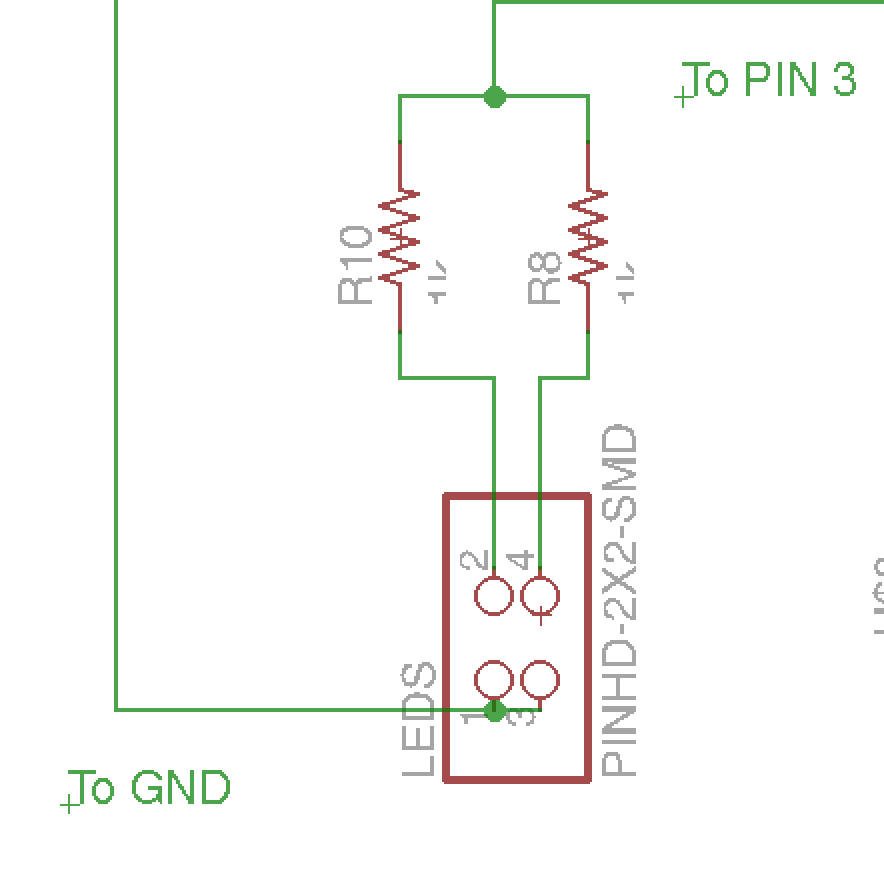
- LED: I used two LEDs in parallel, coupled with a 10k resistor. The LED were materialized by a 2x2 header.
- Heater: I used a 2x2 header coupled with, originally a 10k resistor, and then I removed it because there was actually enough resistance in the heater
First board designed with some different sub-function:

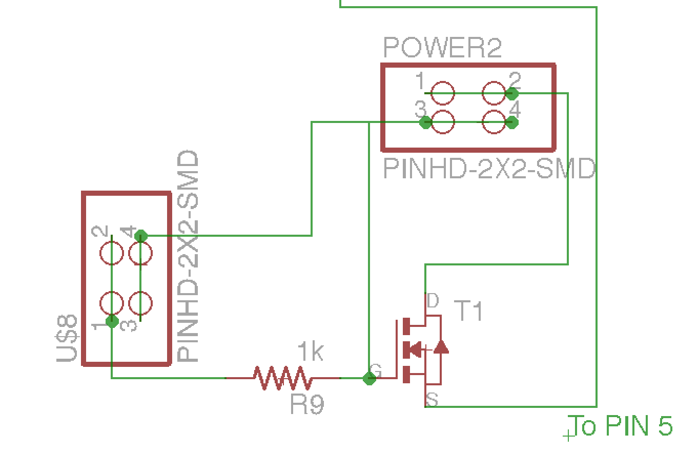
But the actually sinplified design was this following one (without the mistake made on the MOSFETs (see after) and on the Voltage regulator and the FTDI VCC).

The mistake I made with the MOSFET was to invert the direction of sourcing and draining. Originally, I thought I should plug them like this:
But I should have actually done like that

Thus the following pictures show the components used in the different version of the boards milled

Finally, the following picture shows the different iterations in the board and how, with experience, I used less 0k Ohm jumpers and I could reduce the size of the board

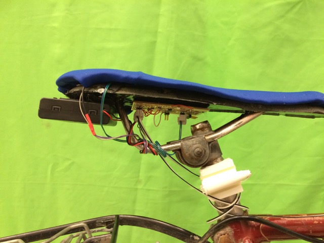
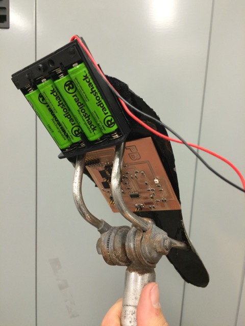
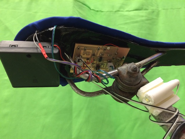
The following pictures show the integration of the board to the saddle with Velcro, and with the batteries

e. Sensors choice
A lot of iterations have been made on the sensor choice, especially to sense the pressure. I tried different types of step response sensor, something relying on the loading model, sometime relying on the Tx/Rx model where I would have the Tx electrode outside englobing the Rx electrode inside a sandwich made of the Tx electrode and foam. I used different material

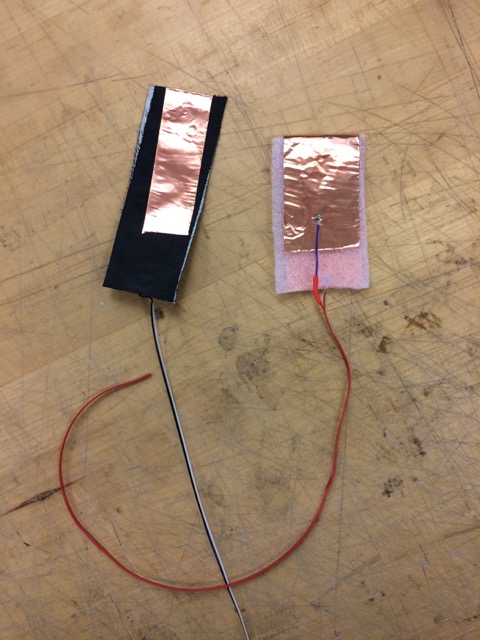
The video shows the different behavior of the capacitive pressure sensor. I tested them with my hand and I noticed that when I used some non skin material, their behavior was much more altered and less sensitive and I needed to use more programming to actually sense the pressure (the change in step response due to the "loading" of the homemade capacitor). I actually decided to use a resistive pressure sensor that we are developing in my lab:
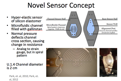
More description can be found in the input page. Those sensors worked very well and I wanted to combine the two sensors: Tx/Rx and resistive pressure sensor in the saddle to sense pressure and actually see their difference in terms of sensitivity and efficiency (the resistive sensor were small so needed to be distributed in the saddle for example):
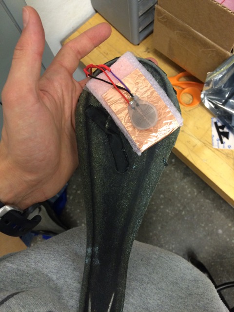

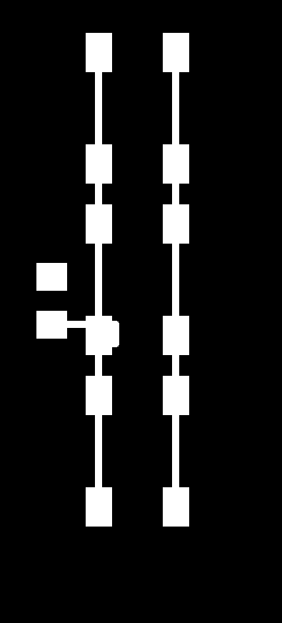
But finally, the resistor pressure sensor broke (it is actually very fragile, especially the connection between the wire and the elastomer and the liquid metal inside), and I did not have time to figure out how to code the capacitive pressure sensor, so, instead I chose a last solution: using a push button, and more exactly a printed board with 3 push buttons in parallel to sense the pressure. I forgot to take a picture of the PCB with the push button integrated to the saddle but the traces in Eagle were:
f. Embedded Programming
This part was not trivial neither since I first needed to "calibrate" the different sensors. But to be short I used the Arduino IDE environment to program the board. The Arduino IDE Serial plotter and Serial viewer were actually very convenient to use. The video on the top describe the calibration process nicely and how to plug the different cables.

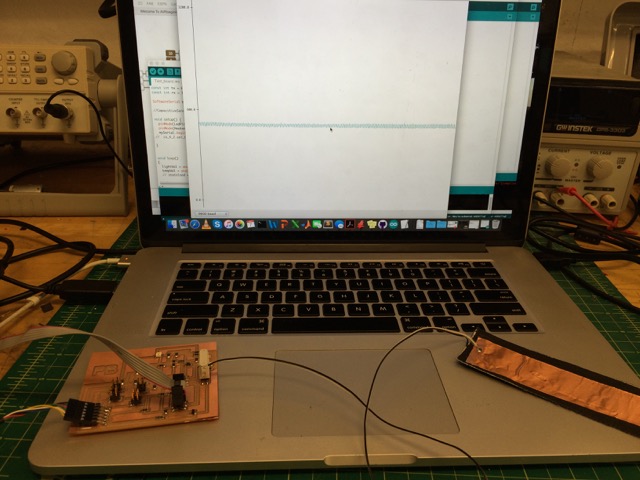
The goal of the calibration part was to detemrine the values of the input devices that wold make the difference between warm/cold, night/day, pressure/no pressure. I thus tested the device separetely going outside when it was day and then when it was night, when it was warm and then when it was cold... I also wanted to have the light and the heater on, even after a few seconds when the biker was standing up. I chose 5 seconds but could have chosen much more. I also tried a blinking LED code if the biker was pushing the bike seat twice. I also needed to determine the Arduino pin number in the Arduino IDE environment (in brown) that are actually different than the Attiny44 pins.
At the end, a simple version of the code is as follows:
#include <SoftwareSerial.h>

int lightPin = A0; // photo transistor (pin 13)
int lightVal = 0;
int tempPin = A1; // temp transistor (pin 12)
int tempVal = 0;
int buttonPin = A3; // temp transistor (pin 10)
int buttonVal = 0;
int resPin = A2; // temp transistor (pin 11)
int resVal = 0;
int LedPin = 9; // LED actuator (pin 3)
int HeaterPin = 8; // heater actuator (pin 5)

const int tx = 6;//Transmit pin
const int rx = 10;//Receive pin

SoftwareSerial mySerial(tx, rx);

void setup() {
  pinMode(LedPin, OUTPUT);
  pinMode(HeaterPin, OUTPUT);
  mySerial.begin(9600);
}


void loop()
{
  lightVal = analogRead(lightPin);
  tempVal = analogRead(tempPin);
  buttonVal = analogRead(buttonPin);
//  resVal = analogRead(resPin);

  //mySerial.println(int(map(tempVal, 400, 600, 1, 100)));
  //mySerial.println(lightVal);
  //mySerial.print(" : ");
//  mySerial.println(tempVal);
  //  mySerial.print(" : ");
  //  mySerial.print(buttonVal);
  //  mySerial.print(" : ");
  //  mySerial.print(resVal);
  //  mySerial.println(" : ");


    if ((lightVal > 1000) && (buttonVal < 1019)) {//If dark and load
      digitalWrite(LedPin, HIGH);
//      mySerial.println("LED on");
      delay(5000);
    }
    else {
    digitalWrite(LedPin, LOW);
//    mySerial.println("LED off");
  }

    if ((tempVal > 585) && (buttonVal < 1019)) { //If dark and load
      digitalWrite(HeaterPin, HIGH);
//      mySerial.println("Heater on");
      delay(5000);
    }
    else {
    digitalWrite(HeaterPin, LOW);
  }

}
g. Conclusion
This project had to be produced in a relative short timeframe and could have been improved by many other ways. Here are some ideas for future work:
- Having a bike dynamo in charge of the power. I actually ordered online a bike dynamo that was too long to arrive and thus I did not receive it before the end of the project, but having a dynamo would allow to power the heater (only, since the power requirements for the electronic board would not be adequate with the dynamo that is an unstable current) without the need of changing the batteries too often
- Nicer 3D printed light holders. During the fabrication process, the 3D prints were not perfectly printed because the file was made for a two heads printer and used a one head printer that did not print the support. One face of the holders were thus not perfectly printed. The 3D printer was not really available at the tiem when I could have printed the design again.
- Nicer mold. During the frabication process, as the support did not stay fixed on the table, the mold had some default. A nicer mold coud easily be remilled but the lack of time forced us to use the existing imperfect mold.
- Motion sensors implementation: we could pilot the light and the heater with motion sensors like accelerometers: when they sense an ecceleration they power the heater and the LED, or when they sense that the bike is a little tilted (turning right or left), they light the turning LED (right or left)
- Wireless communication implementation: It would have been ideal to be able to communicate over the Wifi or through other network with the bike seat to power the heater few minutes before using the bike.