2. Electronics Production
The FabISP In-Circuit Programmer
Milling
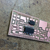
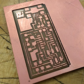 Though I got a fairly late start on the project, this week started out pretty strong. I was able to get the machine running right from the start and got the traces cut quickly. I noticed that there was a lot of fringe material around the traces, and decided that if I needed to redo the board I would be sure to use a sharper 1/64" bit. When I tried to run the 1/32" bit for the outline file, I used the wrong saved file corresponding to my board type. The image to the left is the result, the outline cut into the traces in some areas due to being slightly off-center, and the board wasn't cut all the way out of the stock. I decided that I would try again, but this time I wanted to go for one of the integrated USB designs. I worked for Valentin as a UROP the summer after my freshman year, and I really liked his idea of manually snapping off the parts, as well as the one-time-use assertion, so I thought I'd give it a shot.
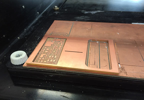
 Once again the traces went very well. This time they were even more defined and less frilly than the previous ones due to the sharper bit as mentioned before. When I machined the outer edge I was sure to pay close attention this time, until about 70% of the way through. At thi point I got too confident, looked away for a few seconds, and when I turned back the part had been lifted from the bed and the bit had cut a gash into the USB section of the board. I went back to the original design, cut the traces (flawless again), and attempted to cut the outline before my 4.601 lecture. At this point the server stopped communicating with the machine and no number of computer restarts would remedy the situation. I went off to lecture and decided I'd try to improvise when I got back.
Coming back from lecture I tried to line up my board in the exact position it was before and cut the outline. This worked a lot better than you'd expect due to a small mark in the copper on the surface from where the tool began to spin at the start of the traces operation. Once I got the server to communicate again (restarting the computer in just the right way), I finished the milling by cutting the outline of the board. After some quick Scotchbrite and rinsing, the board was ready to solder!
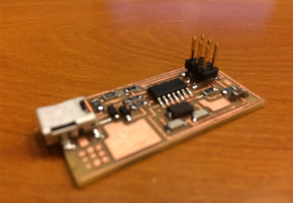
 Soldering the components went very well at first. I was able to get a majority of the components in within an hour. I have a decent amount of experience with soldering just from building little kits in the past for Arduino's and other boards, but nothing this small. I found it easiest to heat up one of the pads, melt some solder onto it, hold the component down on top of that one pad witht the tweezers, and melt the pre-placed solder to surround the joint on the component. This worked impeccably right up to the mini-USB connector. I'm pretty sure I got all of the tiny leads covered well on the first go, but then I went in to clean up one of the joints I wasn't sure about. When I did this I created a bridge between the two joints that took me a lot of solder wicking, sucking, blowing, and cutting to remove.
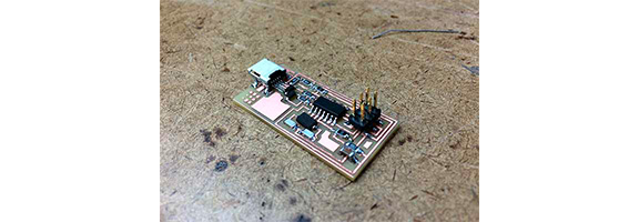
Programming the board wasn't too much of a challenge. When I first plugged the board in I got the error message about drawing too much power and had to go back to that previously mentioned solder bridge to fix it better. After that the process was pretty straight forward. I followed the directions on the fab site and used the computer in the architecture shop to complete the process. I still don't entirely understand everything that happened after the final component was soldered into place, and I would like to keep exploring to play with these things and learn more. Additionally I would like to go back and actually finish Valentin's integrated USB board (mostly so I never have to solder one of those mini-USB components ever again).