Printing the Handle


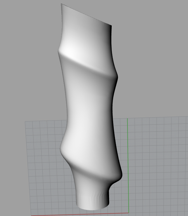
I first cleaned up the model I had designed for the trekking pole handle and decided to 3D print it in two halfs (rather than cast it as I had previously explored) as having two halfs that went together would be easier to work with to get the electronics in. This part also makes sense to 3D print as for now it is just a one off. If I wanted to make multiple it would make more sense to create molds that I could cast from.


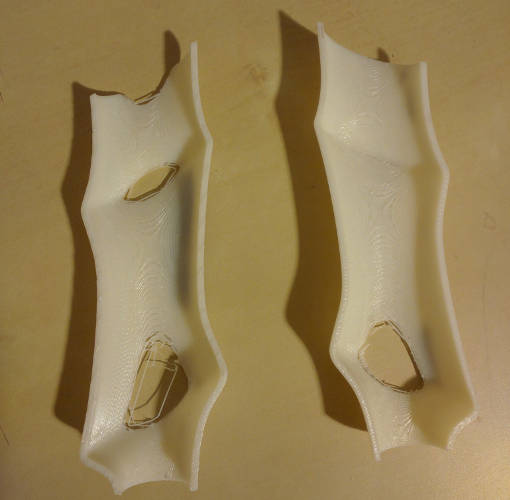
The first print I attempted failed. While the shell was supposed to be 2mm thick, which was within the tolerances of the printer, the geometery did not play nicely with the printer software. I increased the shell thickness to 3mm, and also extended the bottom of the handle by 1 cm to make the interface with the trekking pole shaft easier.


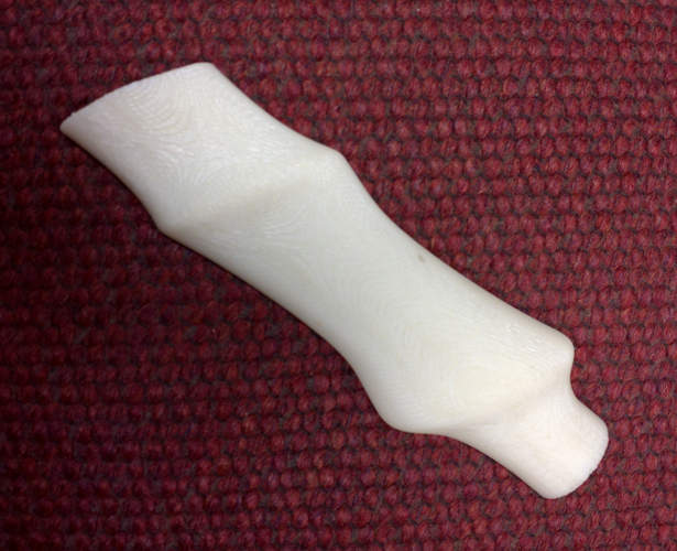
This print was successful and the longer shaft worked quite well.

Printing the Top


I also printed the top of the trekking pole. This was originially meant to be a prototype of a top that I would cast in a hard rubber, but as is expected in this type of project I ran out of time. I used the objet 3D printer for this print, which ended up with a finish similar to what I was hoping to acheive.

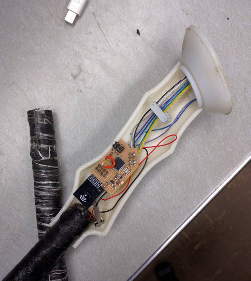
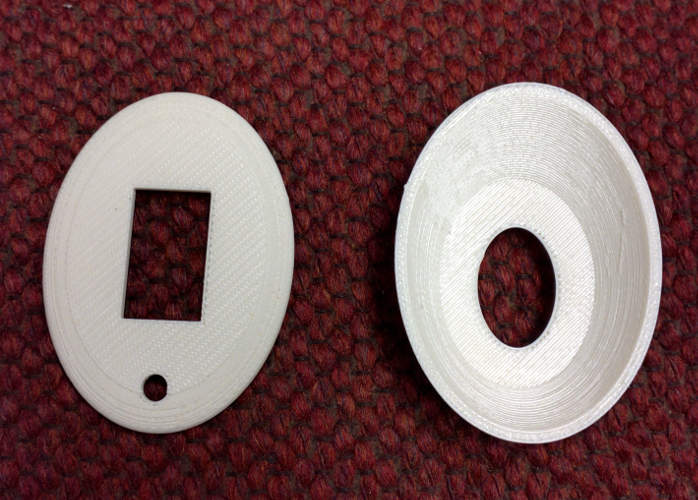
The top of the pole has room for a screen and a button. The dimensions are a little weird because the circuit board that the screen is mounted to is quite large.

I considered casting the OLED screen into the top, but it seemed risky for a last minute attempt.

Casting the Button

There would still be casting though! That would be casting the button for the top of the pole. I simply drilled a few holes of different diameters and depths into the machineable wax.


Then I filled them with oomoo and then placed the buttons face down on top of the hole.


Three out of four of the buttons came out successfully, and I chose the button with the best feel and fit.


Once I had the button cast, I had to embed it into the pole and mount it such that when you pushed the button it wouldn't be able to move and the push could be registered. I attempted to do this by embedding the button in expoy under the lid of the trekking pole.


Unfortuniately I think I ended up with the wrong mixture of epoxy (I had some issues with the pumps), and it has not set up very solid yet. When I last checked it was still a little rubbery, and not enough force was transmitted to the switch.

Designing the Circuit

The body of the trekking pole was fairly small, and I needed to design a circuit that would be able to both talk to the OLED screen and the communications module. This was challenging but fun.

The first version of my board had a slight design flaw in that the RF module was difficult to solder as it was on top of the traces that it was being connected to. This version of the board had a 5V regulator to be able to take external battery power, a 3V regulator to power the RF module, an ISP header for programming, and connections to an OLED screen and the RF module. A external 16 MHz resonator allowed the board to be clocked at 16MHz. As you can tell from the component picture, the board did fit in the handle!

I used a few tricks to make the board small, the most notable being running a few traces under pins on the processor to reduce some of the routing that would have otherwise had to run outside of the board. I am not using all of the input/output pins, so I took advantage of this to run power for the OLED underneath an pin on the processor. I also wanted to get access to A/D Input 7, so I brought it out underneeth PB2 which was being unused.

circuit v2

The second version of my board had the 5V regulator removed as I was planning on now using 3 AA batteries as input, which would provide 4.5V in. This is enough to run the processor at 16 MHz (5V is enough power to run the processor at 20MHz, and people report being able to successfully go past that). I did not fix the issue with the RF module being on top of the traces as it was going to make my circuit a little more complicated, and I didn't want to have to deal with the re-routing at that point.

circuit v3

I eventuially did go back and redesign the circuit such that the RF module could be inserted from the bottom and easily soldered to the pads around the vias. This version of the board also has the ability to wire in the button, or other circuitry, through an extra ground on the OLED pin, and A/D port 7 broken out through PB2. It is even slightly smaller than the previous two boards.


The ports that are broken out are:

Making the Shaft

Based on what I learned about making hollow tubes during composite week with thermoplastic and fiberglass I decided to make my own shaft for my pole. First I acquired a 5/8th inch diameter steel rod that I could use as the internal shape for my mold. This would match the outer diameter of a carbon fiber lower shaft section that I wanted to use with my prototype (and also allow AA batteries to slide into the shaft).

Having learned from my previous experiements, I wanted to try a method that would result in more even heating, and a better interror finish, than using the heat gun. The probem with the heat gun is that while the outer layer of the theromplastic melts together nicely, the interror metal shaft operates as a heat sink and doesn't allow the thermoplastic that it is contacting to get hot enough to really bond together. I thought I would try setting the plastic in an oven so everything could get nice and hot at the same time.


I wrapped a 3 layer shaft that would be melted together all at the same time. The inner and outer wraps were made tightly around the shaft by hand, and the middle wrap was a lot of fibers running up and down the length of the shaft to give it strength along it's main axis. After wrapping it, I wound a layer of silicone rubber around it to provide outside compaction against the inner surface and turned my oven on to 450 degrees.


After spending around an hour in the oven it seemed that everything was at a warm enough temperature that the plastic had melted and the composite has formed. I took the pole out of the over and let it cool down before unwrapping it. You can see in the above picture that the interrior finish is pretty decent, and much better than the previous attempts.

While the interrior finish was nicer, it was also much more difficult to remove from the mold. Instead of the composite sliding smoothly off of the pole, it took amost 2 hours of hammering and twisting to get it off, even thought the pole was ground smooth and had been waxed. It required enough force that I ended up with blisters at the end of the process. It makes a big difference when the interrior is composite as opposed to still being fibers.

The next step is to epoxy the outside of the pole to wet any of the fibers that have not been captured in the plastic. All of those white fibers are exposed fiberglass that we don't really want around.


You can see that after a single layer of epoxy the fiberglass is nicely whetted and the pole becomes nice and glossy.


Once it has dried a little the finish is quite nice.

Connecting Power

This ended up being surprisingly difficult. My original plan was to use AA batteries in the shaft of the pole that I had constructed. While the inner diameter was slightly bigger than a AA battery, it was very difficult to get an electrical connection bewteen multiple batteries and also fit all that additional material down the pole. A lot of this had to do with the fact that while the inner surface of the pole wasn't quite smoothly finished and fibers would get caught on whatever you tried to put down there.


This is an initial prototype where I tried just using a wrap of duct tape to secure batteries against each other, with some aluminum foil between the contacts to aid in maintaining the connection. While it worked OK, when trying to shove this down the interrior of the pole the wires would pull out and electrical connection would be lost. Each AA battery is 1.5 V so I would be supplying my circuit with 4.5 V.


To give myself more room to work with I decided to switch to AAA batteries. While they contain less charge, they are also 1.5 V and 3 would still give me the voltage that I needed. For more perminant connectons I superglued battery clips to the AAA batteries and used a little bit of foil to ensure there was a good connection between the leads and the batteries. I then used wire to connect the three batteries in series, and connected this to my circuit in line with a switch so I could turn the battery power on and off.


This was able to successfully drive the circuit and fit down the shaft of the pole!

Attaching the Screen

In a final version I would want to cast the screen into the top, but for this prototype I simply used hot glue to attach the screen in the proper orientation.


I also superglued the top into place on one of the pole halfs.

Writing the Code

I was able to build on the code from my previous experimenting with the GPS unit (where I used it as an input device on an 11 hour drive and wrote an application to track my path) into a final version that would work for the application of the pole. For the prototype I am passing GPS information from another processor through the RF module. This information is then being used to indicate which direction north is.

Getting the GPS information and transmitting it to the pole was all the same, the more difficult aspect was outputting a directional indicator on the OLED screen. I decided to accomplish this by taking a generic triangle with defined corners and rotating it around a central point. If I started with the generic triangle pointing north, then a counter-clockwise rotation by x degrees would then point the arrow towards north if I was walking at bearing of x degrees.

You can use a simple Rotation Matrix calculation to perform the rotation

// Generic Arrow Datastructure // centered around origin float genericArrow[3][2] = { { 15.0, 0.0}, {-15.0, 7.0}, {-15.0, -7.0} }; // translate heading into radians heading = GPSbuffer[3]*180.0/3.1459; // rotate point x1, y1 rotatedArrow[0][0] = genericArrow[0][0] * cos(heading) - genericArrow[0][1] * sin(heading); rotatedArrow[0][1] = genericArrow[0][0] * sin(heading) + genericArrow[0][1] * cos(heading); // center in screen rotatedArrow[0][0] += 64; rotatedArrow[0][1] += 16; // rotate point x2, y2 rotatedArrow[1][0] = genericArrow[1][0] * cos(heading) - genericArrow[1][1] * sin(heading); rotatedArrow[1][1] = genericArrow[1][0] * sin(heading) + genericArrow[1][1] * cos(heading); // center in screen rotatedArrow[1][0] += 64; rotatedArrow[1][1] += 16; // rotate point x3, y3 rotatedArrow[2][0] = genericArrow[2][0] * cos(heading) - genericArrow[2][1] * sin(heading); rotatedArrow[2][1] = genericArrow[2][0] * sin(heading) + genericArrow[2][1] * cos(heading); // center in screen rotatedArrow[2][0] += 64; rotatedArrow[2][1] += 16; // output the rotated triangle display.clearDisplay(); display.fillTriangle((byte) rotatedArrow[0][0], (byte) rotatedArrow[0][1], (byte) rotatedArrow[1][0], (byte) rotatedArrow[1][1], (byte) rotatedArrow[2][0], (byte) rotatedArrow[2][1], WHITE ); display.display();

This code works fairly well. The arrow gets a little distorted as it travels around in a circle because the vertical spacing of pixels and horizontal spacing of pixels is not identical on this OLED screen. You can see it seem to stretch as it points horizontially and shrink as it points vertically.


This is simulating a complete rotation in software.

Final Assembly

I did have to fix a trace that lifted up from one of the pins.


Everything fit together fairly well.


And could be closed. Now all together!


Pole Cap STL files (bottom, top)
Pole Handle STL files (left, right)
Eagle (board, schematic)
Code (GPS xmit, Screen Pole)
Non-standard components: GPS Chip (~$30) and OLED Screen (~20$)