EAGLEcad | fabmodules | Roland Mill | AVRgcc
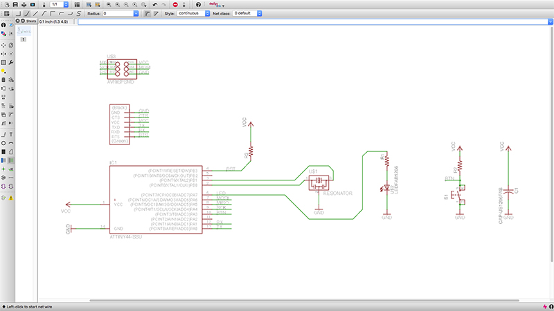
This week's assignment was to redesign the hello_echo arduino board with an added input. Completely new to circuit design, I spend the bulk of my time learning to use the EAGLE software for computer aided design of circuitry. We start with a schematic which contains all the components for the board organized and connected only concpetually. Although the hello_echo board uses an AVRMega chip, because I only planned on using two more pins than the unedited version, I chose an ATTiny44 chip. The pins were connected to their respective addressees, namely a button, an LED, the two headers, voltage, and ground. Eagle actually allows you to create a namespace for the connections themselves, making it very easy to organize your schematic to your own preferences because you're not obliged to draw nets crisscrossing the schematic.
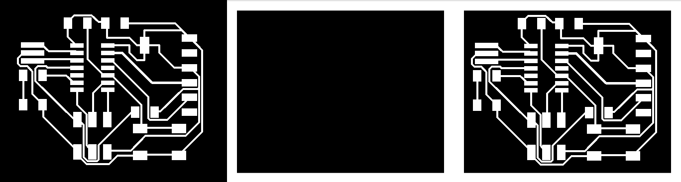
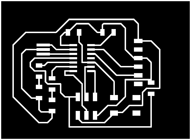
Once everything is connected correctly, Eagle can convert this into an actual board with pads and traces. To do so, one is required to place the components in 2D space, with connections drawn as straight lines. The software also contains an anto path generator, which can generate paths which connect but don't cross. I found generally that it was able to effeeciently find a path for all but one or two connections. The program solves this problem by routing them across the theoretical other side of the board, and they show up in an inverted color to those on top of the board. After finding a design I liked, with one very short routing underneath. I decided it woudl be feasible to use a jumper to keep that one path on the top side of the board. I went back into the schematic, and added the jumper to the appropriate connection, then returning to the layout, I could run one path underneath. It strikes me that for more ccomplex boards, it would be very useful to be able to use the other side of the board, as reverse engineering which leads need to cross over which other leads and correctly inserting jumpers likely isn't sustainable.
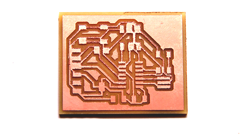
These traces, as well as the border can now be sent to the CNC mill, and the process from assignment 3 (the fabISP) is largely repeated (mill, clean, stuff).
Unfortunately, attempts to mill it out proved far more difficult than with the premade and extensively tested fabISP. I found a few things to be causing problems. First, the auto path generator in Eagle is nice but too much of a crutch. A TA told me "it should give you a general idea of what might be a good layout, but you gave it the positions initially, and you should make the lines yourself too, at the end of the day." Next, the design rules may pass with the fab.dru file, but that doesn't necessarily mean fabmodules will run the file correctly. Finally, the export function in eagle, photoshop, gimp, or whatever 2D illustrating program you're using, will have a setting for dpi (pixels per inch) which should always be set as high as possible to ensure you don't lose any geomtry when the cam software reads it. Actually I had problems or failures in all of these, leading to a board that can't be stuffed, as well as one whihc might although it would take serious work to correct the errors in milling and separate paths that need to be separate.
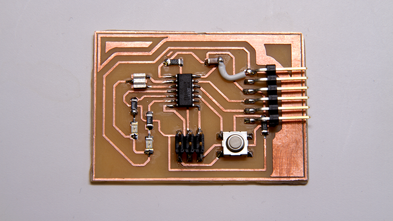
On wednesday, after class, I went through another round of CAD in Eagle and another round of milling to try and get it right this time. Instead of relying on the auto-route, I let it give me an idea of where the path planning might go, but then I ripped most of them up and remade them myself, paying more attention to the bounding boxes and margins. The resulting board was bigger, more open, and looked a lot sounder than the last.
Then the next day, after sanding and finishing the board, I was able to actually stuff it, and as Neil expressed in class, I am getting decidedly better at soldering tthrough the practice of making these boards. Disappointingly, I managed to somehow leave out one necessary lead from the board, and had to subsitute a small length of wire. Oh well. At least it works now.
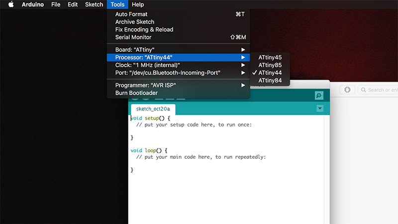
Unlike the fabISP, AVRdude is not necessarily needed to program this board, aside from the initial program I think. I've looked into using the arduino IDE for non arduino boards. Initially this was because the board called for an AVRmega, which is similar or the same as the arduino mega chip, and can be programmed in the same way. Still, I found libraries which allow Arduino to program ATTiny boards, including those with ATTiny44 chips.