Technologies Used
Eagle was used to design the circuitboard.
The skills learned in Electronics Production were used to make it.
Personal Project Goals
This week we looked into the problem of designing electronics. While we had actually produced electronics before, this is the first time we were doing any sort of design. This week was fairly gentle, but was an intro to a field with a very broad scope. I spent a lot of this week learning what tools work and what tools don't, and trying to understand the science of circuits as well as possible.
Methodology
This week had a lot of pitfalls, so I'm going to go through what worked and what didn't in depth.
Read More / Hide
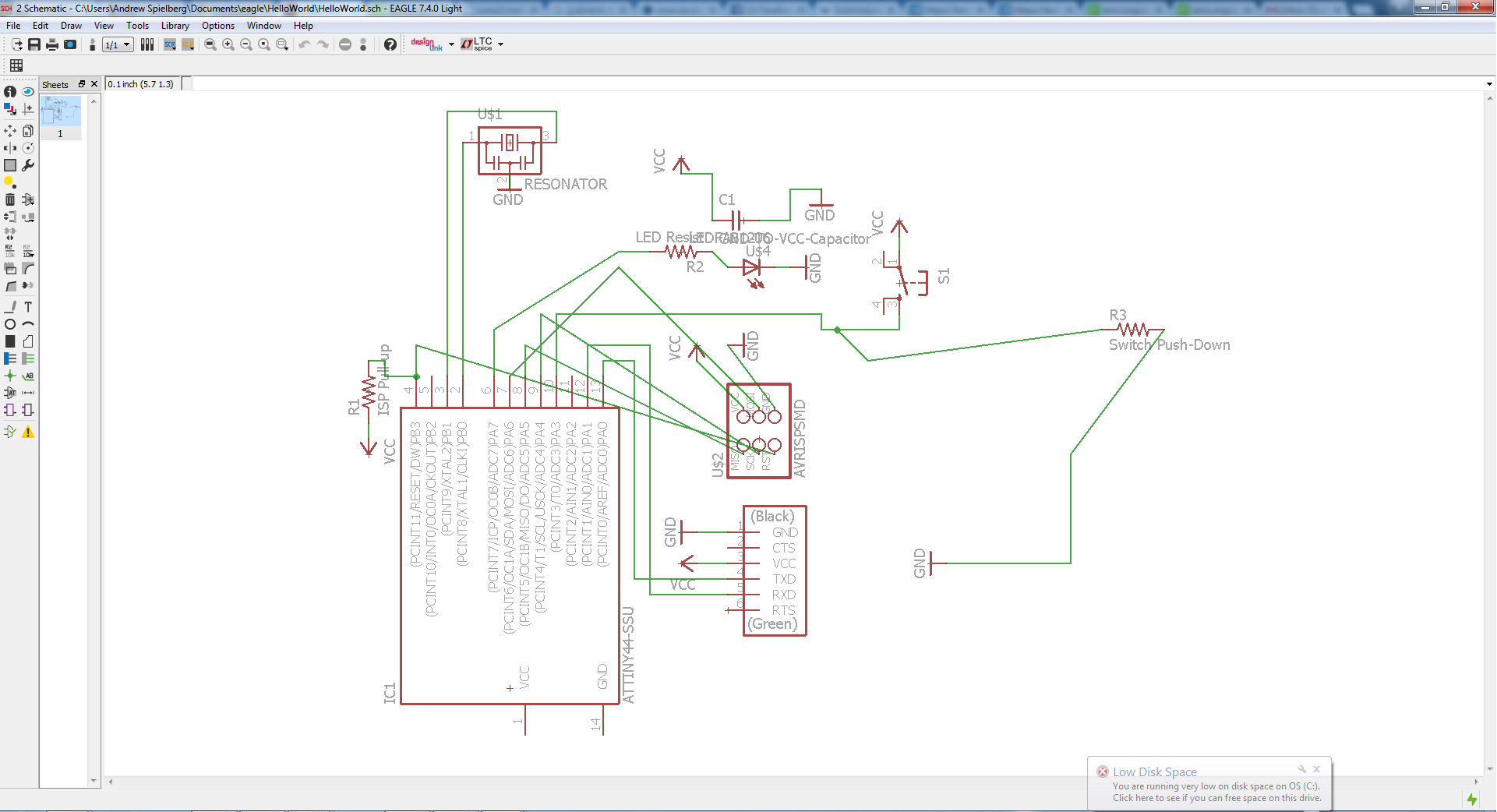
The first step of this week was to simply design the electronics - that is, design the high-level circuitry that will make our circuit go. To begin, we had to add an Atmel (ATTiny44) to a PCB board. This requires a few steps in the design process, such as adding in a capacitor to make the programmer compliant with the standards, and adding a pull-up resistor for the connections. This was done straight-forward symbolically using Eagle. My circuitry is sadly a bit of a mess - I didn't mind because it was simple, and didn't want to add more room for failure by adding symbolic annotations when I wasn't yet sure how they are interpreted. For future designs, I will make a cleaner symbolic design. In order to fulfill the project requirements, I added a pull-up resistor+switch, as well as an LED (with a resistor to make sure it doesn't short-circuit!)
Routing the board was much more nontrivial. There were several pitfalls. First, I tried to use the auto-router, and I gotta be honest - not as bad as everyone said! I think if the design rules, grid sizes, and wire thicknesses are set appropriately, the auto-router can be a valid tool. At the least, it can check for feasibility for your orientation of parts. If the auto-router, doing all the tricks and hacks you don't want it to do can't find a solution, then you're not going to find one the right way! I think a very reasonable workflow is to let the autorouter find a "coarse" routing, and then for a user to go through and clean up the routing starting from its suggestion. I think I'm in the minority though.
The second mistake I made was to route with the default grid size. Again, big mistake! In order to get this design to work without jumpers, you're absolutely going to need multiple wires to go under the microcontroller's footprint - this should have been obvious from the example board. After a while, I drastically shrunk the grid size, and started to base my board off the example one as a starting point, and was able to get a reasonable design.
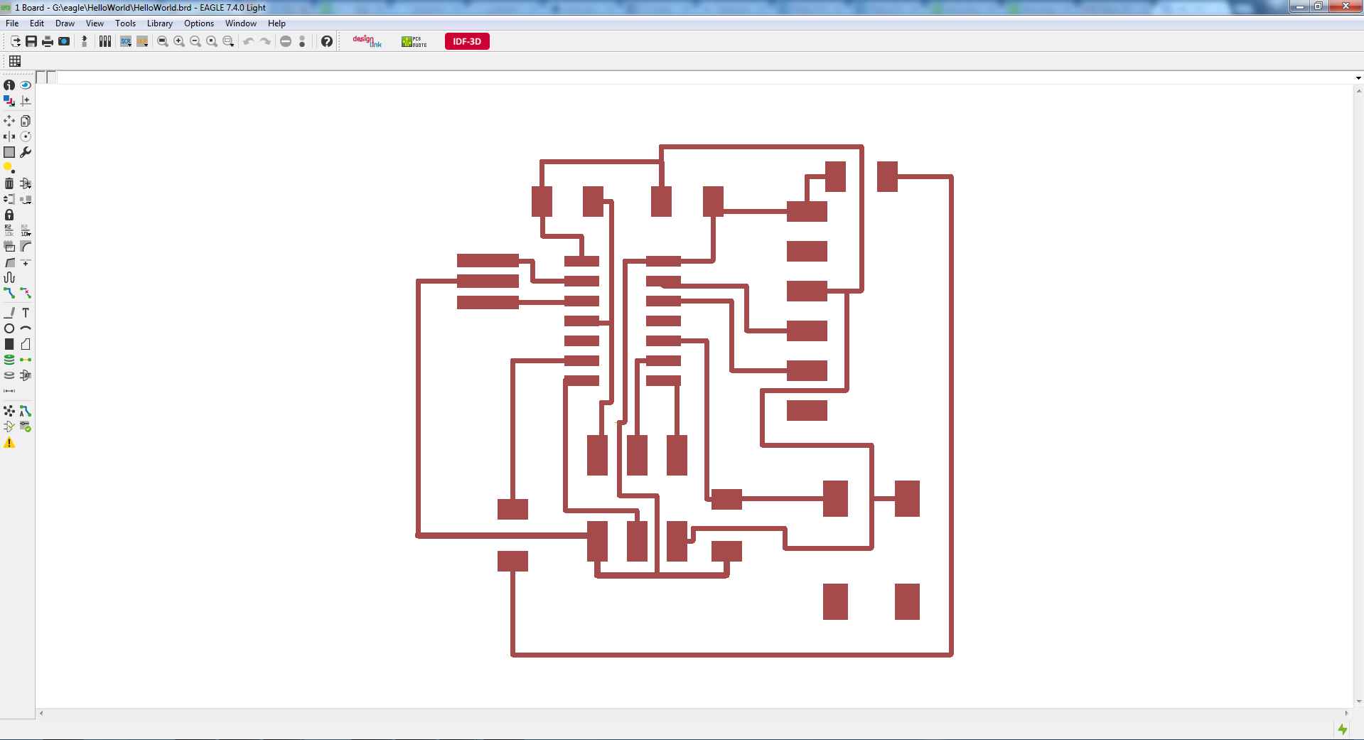
The third big mistake I made, though, was relying on too lenient design rules. Don't completely trust the design rules! When you pop your png into fab modules, make sure you check the mill path to make sure it's separating out all your traces. My first routing didn't put enough space between a few traces, and they all blended together. I decided to scrap that one.
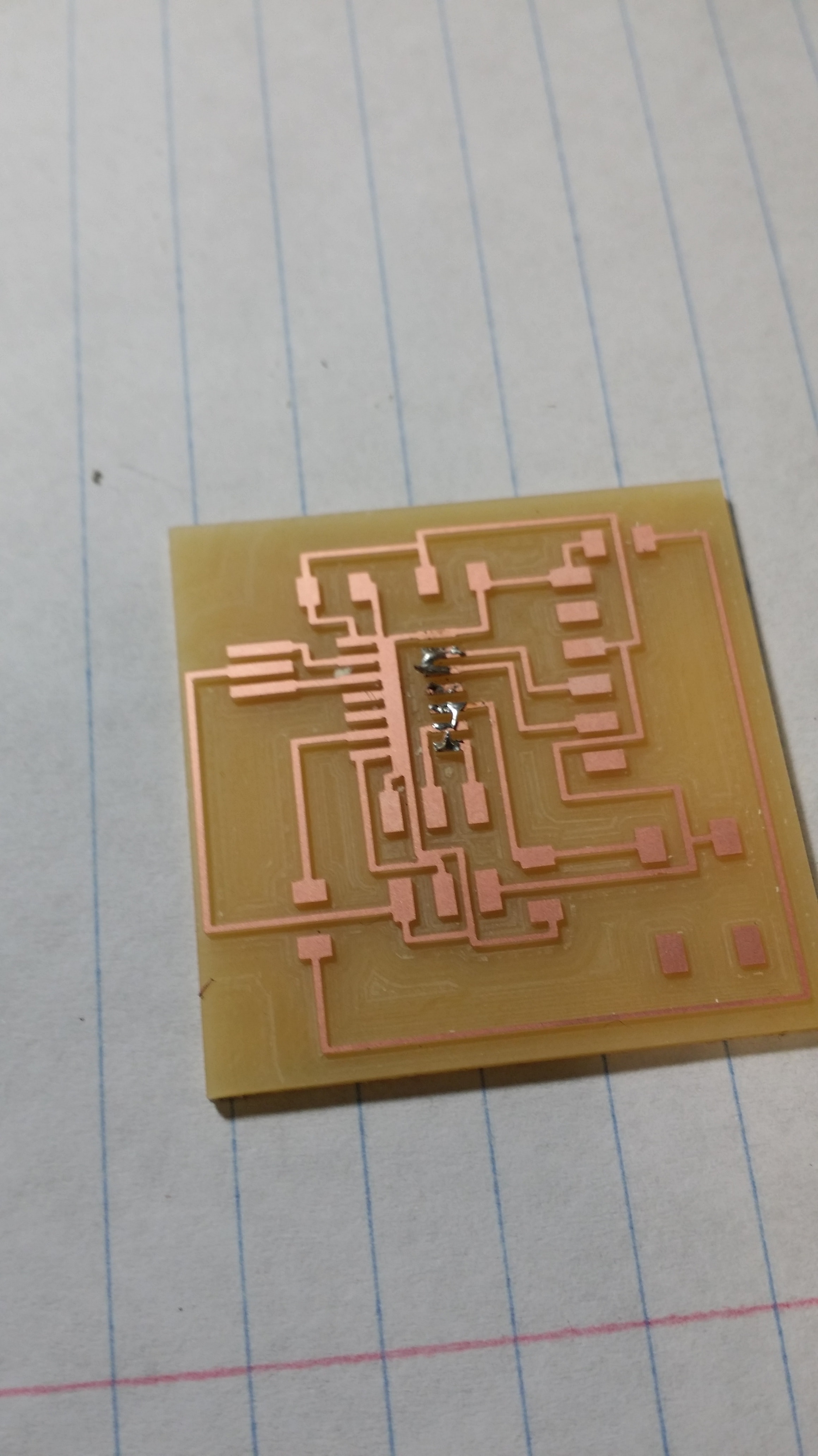
The second board just had two traces merged (which I should have noticed but didn't), which I was able to easily separate afterward with an exacto knife. The only sad thing here was that the tape came off a bit when milling, so the cut around the edges on this board is ugly.
My board can be found here and the schematic can be found here.
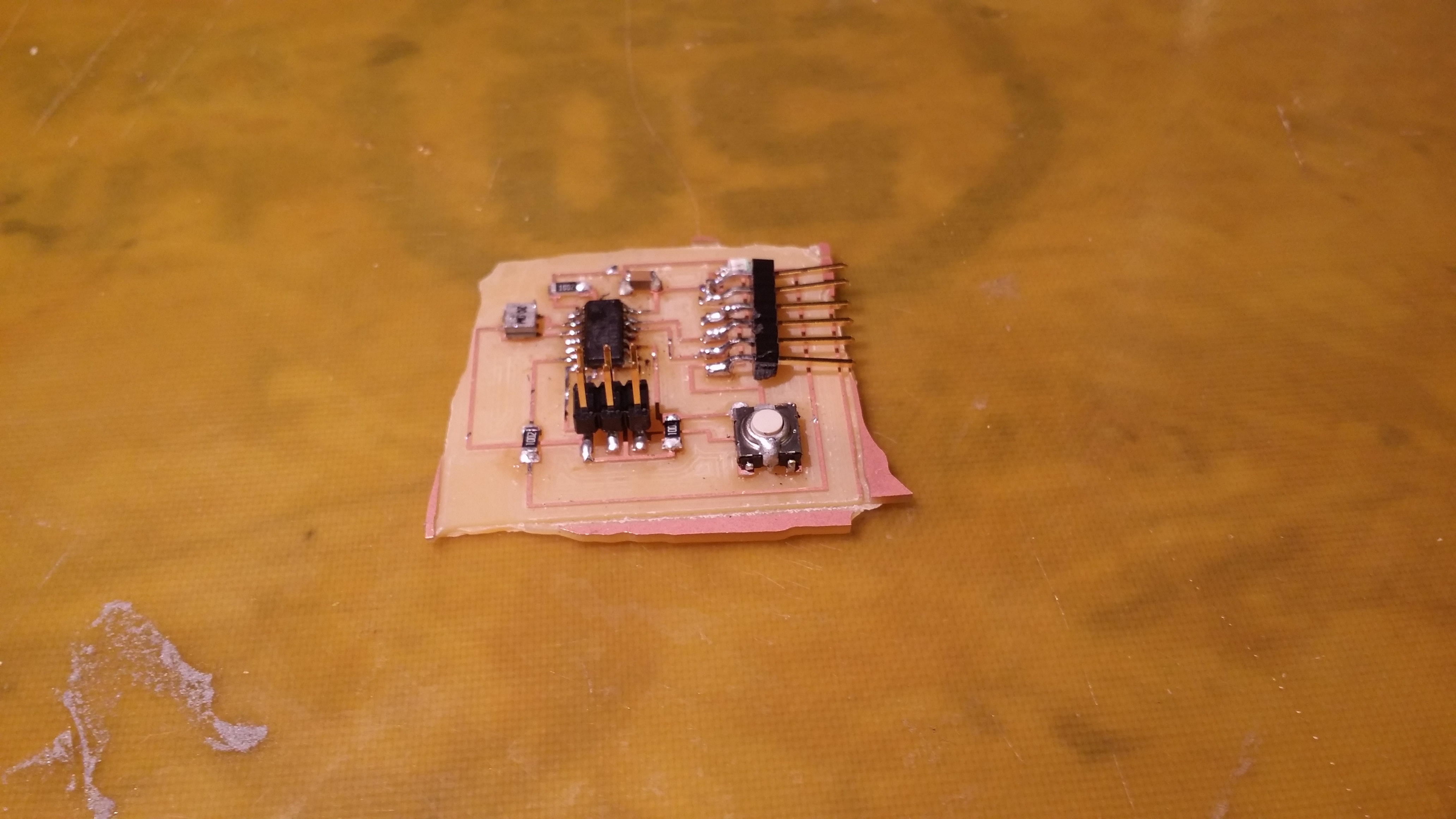
My soldering skills are still not great. I'm sure they'll get better with time, though.
Current Issues
Everything is good to go right now for the objectives of this week. In the future, when I get free time, though, I plan on looking into programmatic specification of boards using fab modules. That's way more my style B-).