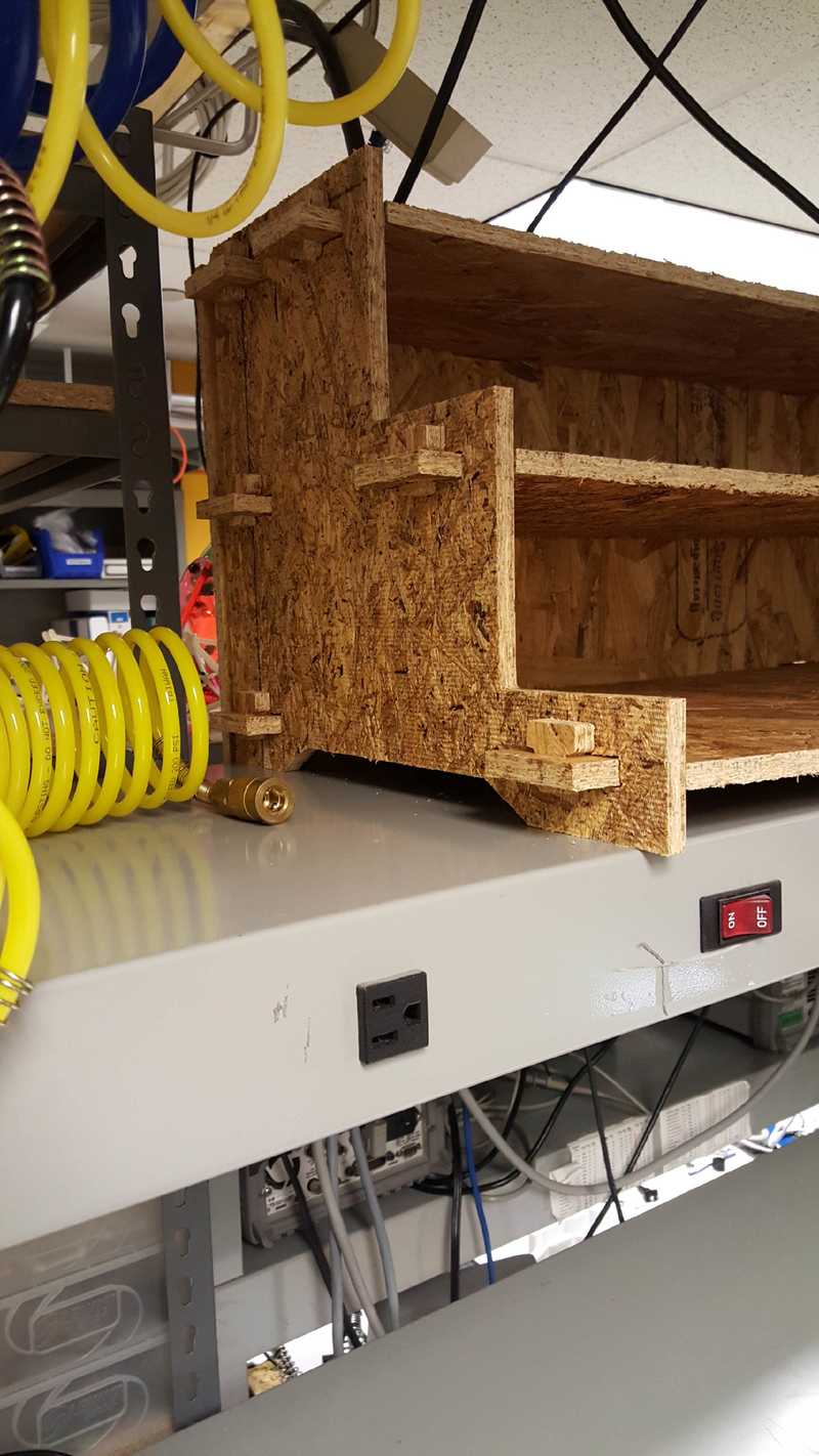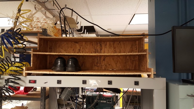
This is a shoe rack constructed from a single sheet of awful OSB plywood cut on a ShopBot. Other than fixturing, no additional tools, glues, screws, or nails are required. Even assembly can be done by hand, though gloves may reduce the number of bandaids used for splinters.

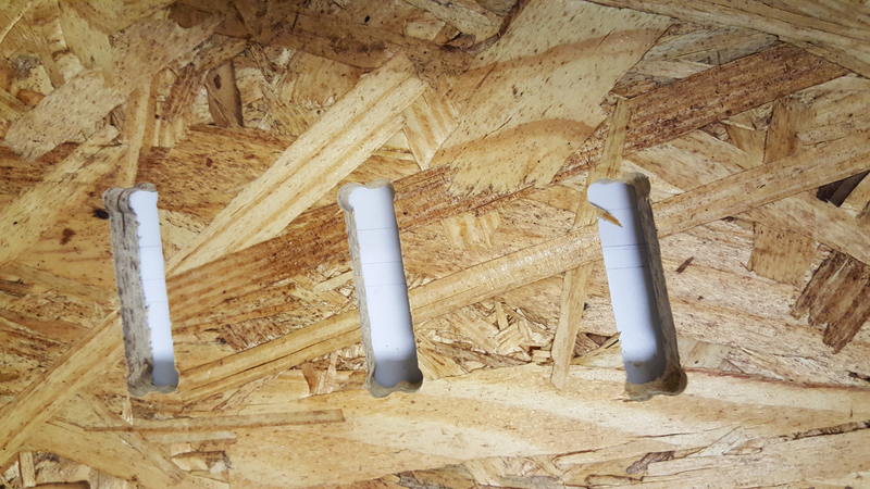
All the joints in this design are a repeated slot and peg system. A tab goes through a slot, and then a t-shaped peg goes through a hole in the tab. This creates a tool-less 90 degree join.

The tab in slot constrains in 3 dimensions: Linearly in Y and Z, rotationally on X. The flange (hidden) and the peg constrains linearly in X. This leaves two dimensions unconstrained: rotation on Y and Z. These constraints come from multiple joins working in concert.
The peg is tapered 5 degrees to create some retaining friction. A small fillet on the inserting end aids assembly. The 2.5D manufacturing method doesn't allow for fillets in the other dimensions, though a pocketing step may have been used. I chose not to dogbone the inner corner of the peg just in case they came out too small. As is it worked well, though I might lengthen the peg in a future revision.
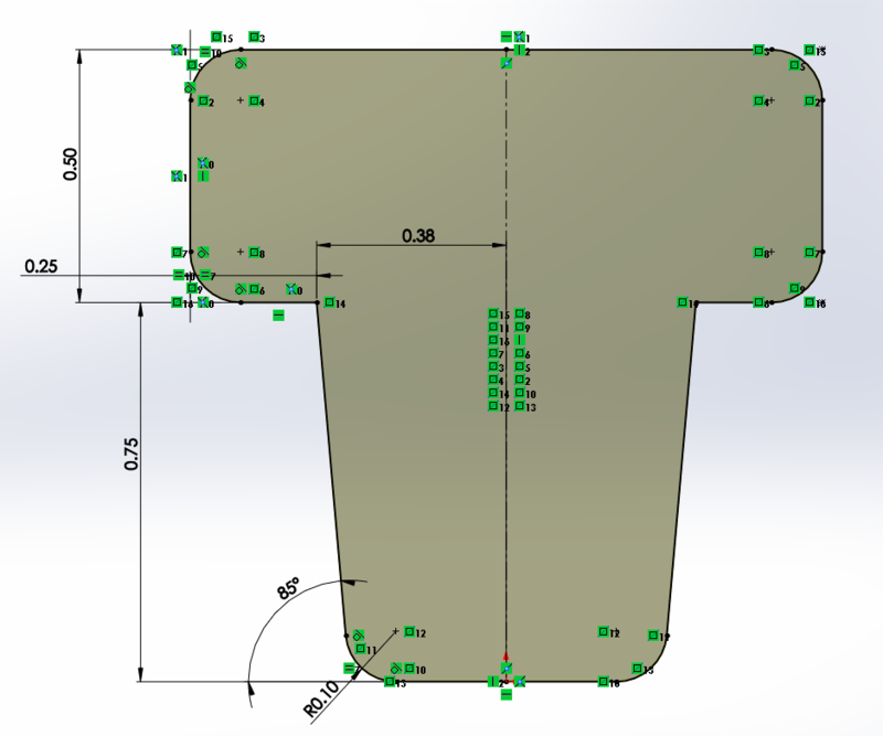

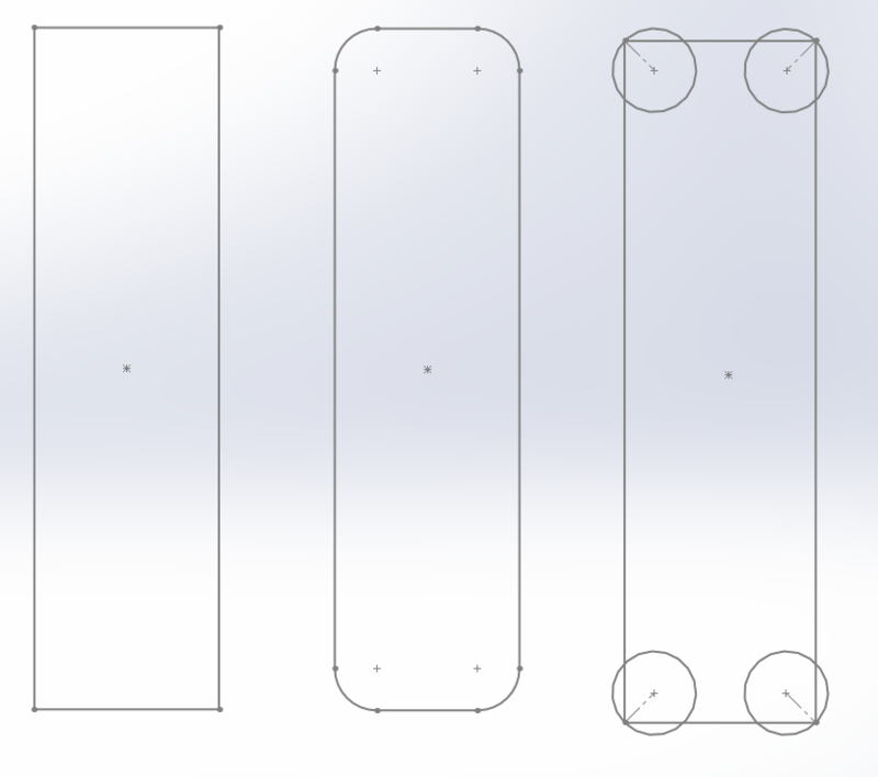
Each of the 3 shelves used the same base design, but they each have a different depth. The screen shot above shows three design parameters are linked to global variables or equations. After designing a generic shelf I created three specific instances.
I ended up doing this by cloning the file as "Tray 8", "Tray 12", and "Tray 16". There is likely a better way, but I was afraid of creating a circular dependency.
The master model has a parameter for this thickness; updating it propagates through the full design. This worked relatively well for the shoe rack design. I had also designed a projector mount, but I had done this before Matt taught master modeling. I was unclear on the scope of the so-called "global variables". It turns out that the scope is limited to the individual parts without the explicit externing of the master model, so these changes did not propagate as I thought they would. This was an unfortunately fatal flaw in the projector design - the slots were cut too narrow for the actual wood thickness.

The cutting bit is incapable of cutting internal corners with a radius smaller than its own 1/4" diameter. The target cut (left) is not feasible. Without compensation it creates internal fillets (middle), which would interfere with the square-edged tab attempting to go through it. Dog-boning (right) cuts additional material away to give the tab sufficient room. This preserves the length and width of the cut as long as the slot width is larger than sqrt(2)*Cutting Radius, assuming 90 degree corners.