I used Solidworks to model the Truffle Mold. I've collected a few tips to make this easier.
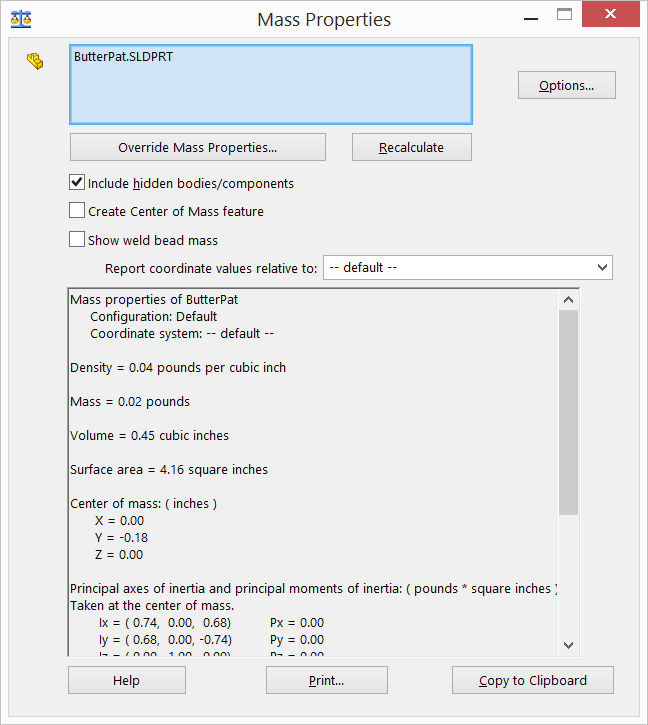
I used the Evaluate -> Mass Properties to check the volume of the part. Butter pats and Truffles are typically 1.5 teaspoons, or 0.45 cubic inches. I tweaked the depth until the desired volume was achieved.
Draft is less relevant using flexible molds, but can still be helpful. This tool makes it easy to identify regions in the design that may have difficulty releasing from the mold. I temporarily disabled the draft on the font and increased required draft to 18 degrees to highlight this.
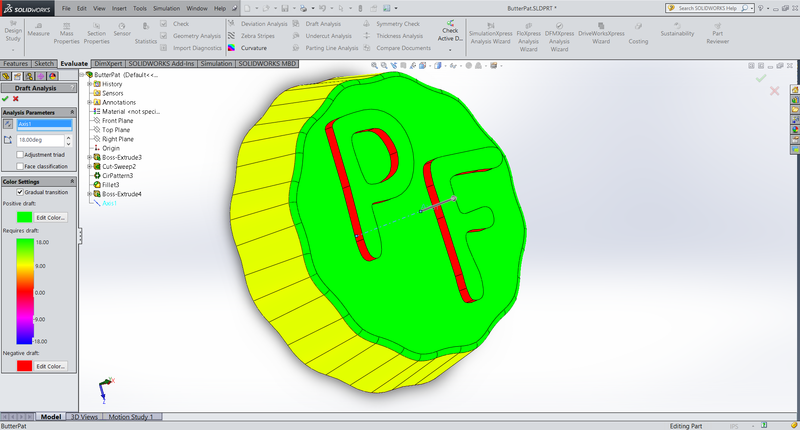
The font walls are now shown in red to indicate that they are perpendicular to the mold pull, which may make demolding difficult. The yellow walls indicate sufficient draft given the requirement set.
In retrospect, the text is likely too short to cause problems - it is shorter than the ball end mill's radius, so the entire sidewall is already going to be filleted whether I model it in or not. Additionally, the molding compound I used has a relatively low durometer, making it more forgiving.
Arranging Multiple Parts using an Assembly
I wanted to maximize the number of butter pats that I could fit within the block. To do so I made an assembly
The block was 3"x3.5"x1.5". I started with a 3"x3.5" rectangle, and then nested two additional rectangles inside of it. The first shows the fence width of 0.150". The second is the keepout to allow the mill to get in between the fence and the model. Even though I'm using an 1/8" bit, I gave slightly more distance just to be conservative.

I then imported the part 4 times into the assembly.
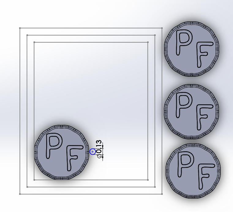
I created a second sketch with a circle with the same diameter as my tool to assist in arranging parts. Shuffle them around until they fit well.
The Clearance Verification Tool is great for checking your arrangement. Here it has identified that two of my butter pats are too close together. Go to "Evaluate -> Clearance Verification". Use "Selected items and the rest of the assembly" and set the clearance gap to your tool diameter. Select each of your parts one at a time and hit calculate. If an error is detected it will silhouette all the irrelevant parts and highlight the gap.
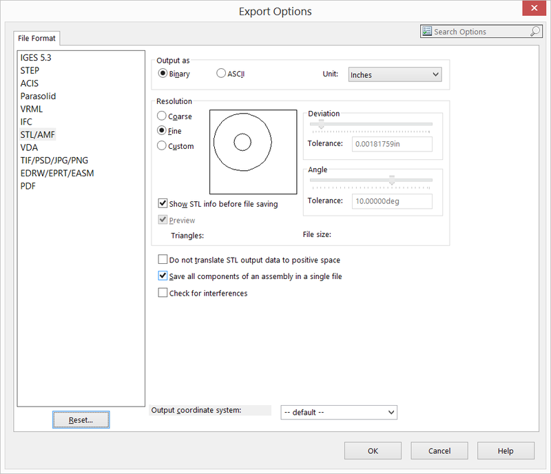
Select "File-> Save As" and choose .STL as your file type. Open Options and select "Save all Components of an assembly in a single file"