I made the Hall effect sensor as an example. Milling the board, stuffing the components, and programming the chip was the same as usual. To read the magnetic sensor data, however, you first need pyserial (plus python, obvi) and tkinster (if you're using Neil's code). Using Cygwin terminal:
tar xvf pyserial-2.7.tar.gz pyserial-2.7/
cd pyserial-2.7/
python setup.py install
python
import serial
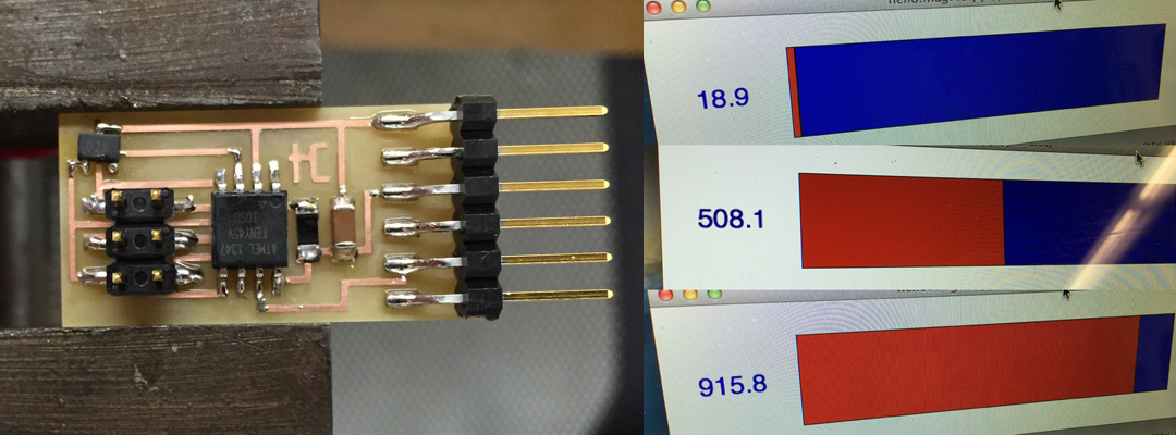
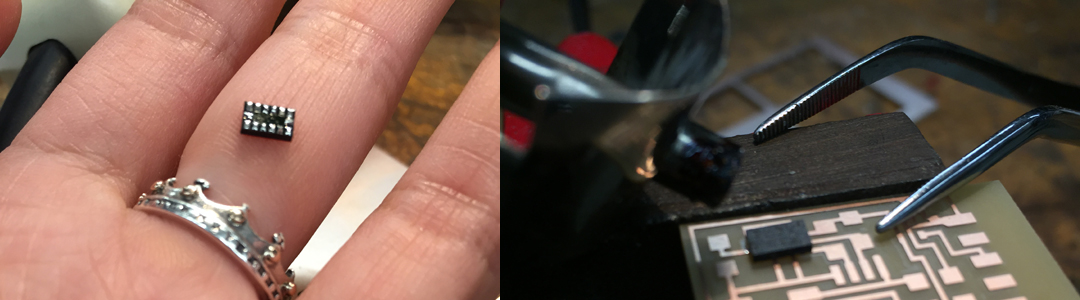
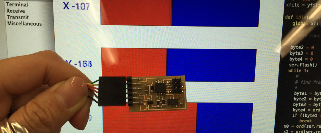
Naturally, I moved to the accelerometer next (ADXL343 data sheet here). I think my soldering game is pretty boss, but that accelerometer was not easy! Its solder pads are tiny, so I very carefully aligned the component to my board and used the reflow technique... but it took me several attempts before Neil's python program could display each axis correctly.
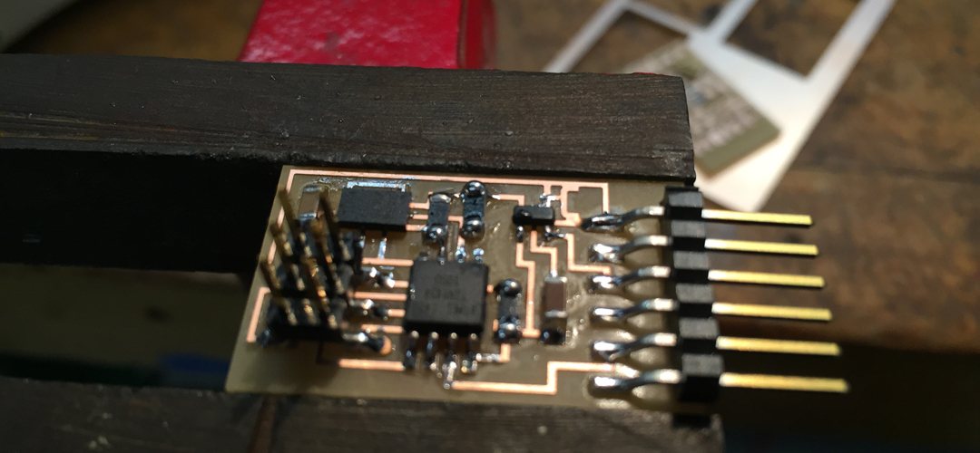
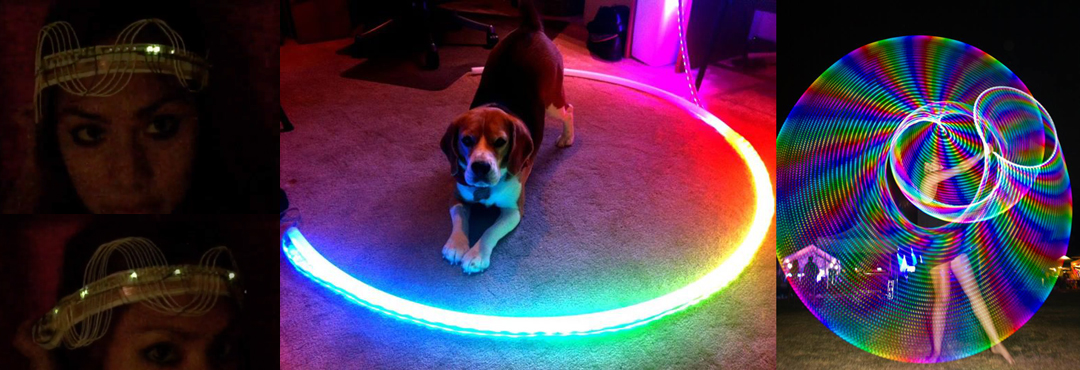
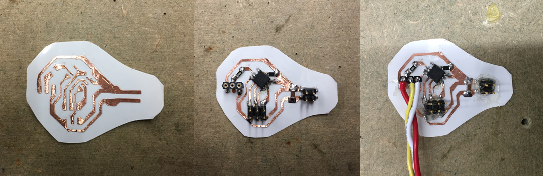
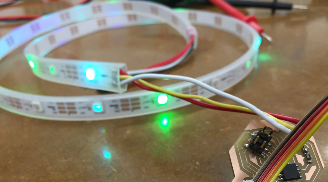
My next step was to see if I could drive my WS2811/WS2812 RGB LED strip with an ATTiny, and then combine it with the accelerometer. It has enough I/O pins and should work with my sensor. I wired up a simple circuit connected to the LED's 3 leads (5V, Data, and GND). Unfortunately, this is where it all goes downhill... I used Arduino this time, because Adafruit has a Neopixel library that includes support for the ATTiny. But everytime I tried to burn bootloader, I receive the dreaded error -- avrdude: initialization failed, rc=1!!!
I TRIPLE checked my connections (and trust me, my soldering is very good), but avrdude -p attiny45 -c usbtiny yields the same exact results, meaning my fabISP (I also tested with AVRISP MkII which gives the green light but same issue) can't talk to the chip. I made several versions of the very simple circuit and concluded that after burning the bootloader, it somehow destroys the chip... because before burning, avrdude tells me it's ready to be programmed.
My only guess is that the small ATTiny45 chip is unequipped for this job (perhaps 4k of memory isn't enough?), but the lab doesn't have any ATTiny85 (at least the Harvard section has never stocked it). I'll ask Rob to purchase (or ask MIT secions), as I'm anxious to get it programmed. Wahhh!
So I went to go see Neil play the bassoon at Aeronaut Brewery. Quite a few MIT Media Lab folks were there and I got to chat with Dan, who mentioned that setting the wrong fuses could render my chip lifeless. And that was exactly it... I had been setting an 8 MHz external clock instead of internal. You can hook up an external resonator to correct this, but I just opted for replacing the ATtiny.