week 9: input
For this week, I played around with two types of input, each using the built-in ATTiny ADC hardware: first, an electric microphone for audio input, and second, a step-response analog sampling to measure changes in capacitance.
mic input
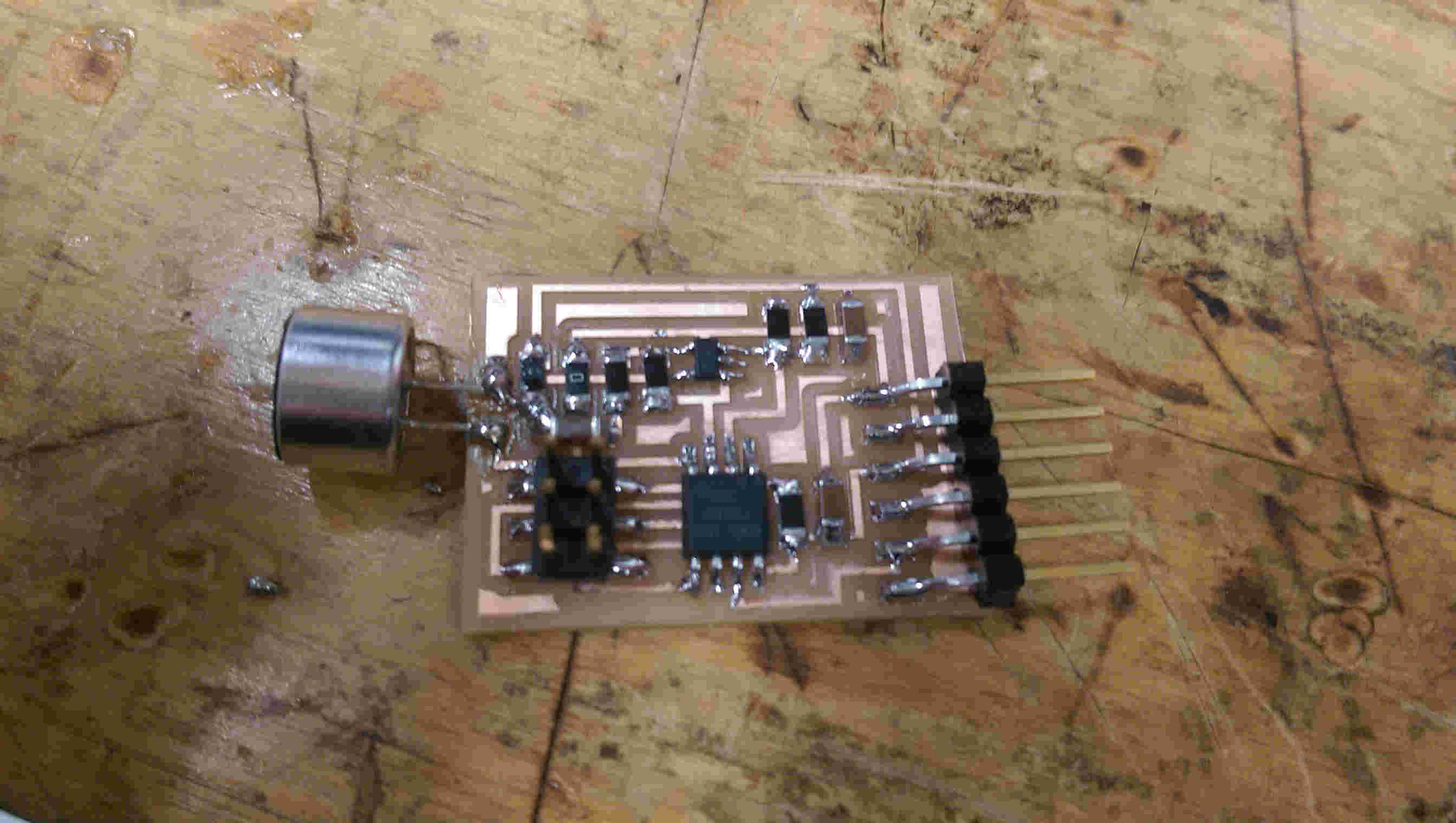
I chose to play around with the hello.mic.45 board since I was interested in using Ag-AgCl skin electrodes to measure analog input. Since the board already had an op-amp built in, I thought a zeroth-order attempt could try replacing the mic with output leads to go to skin electrodes.
hello mic
initial result: noise
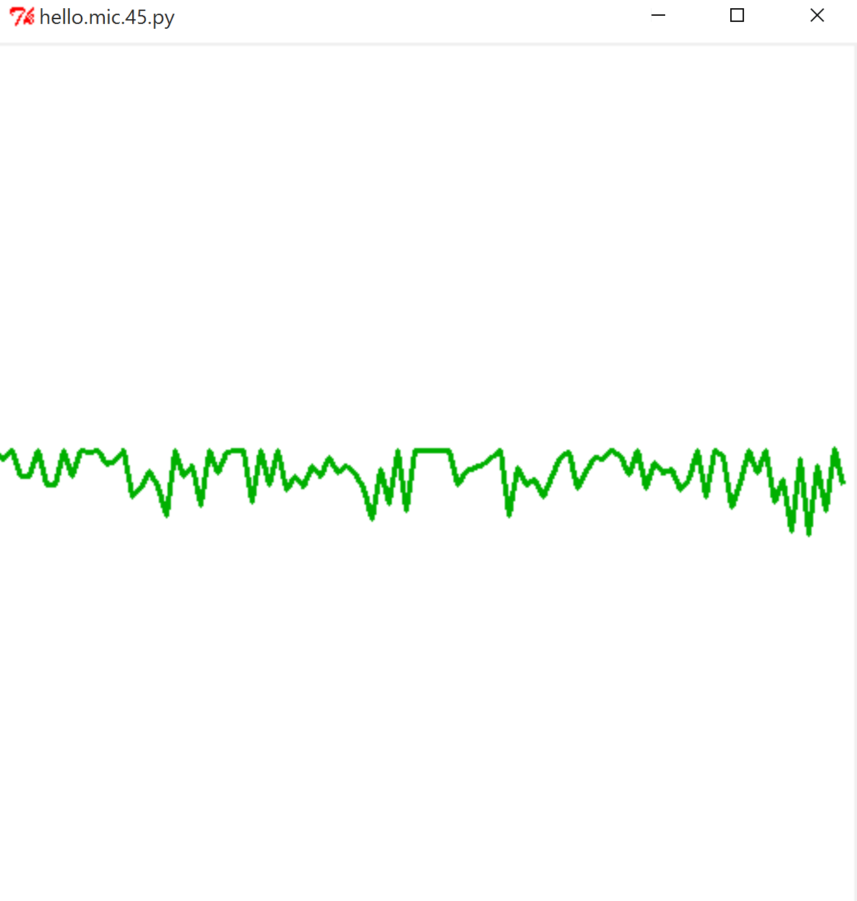
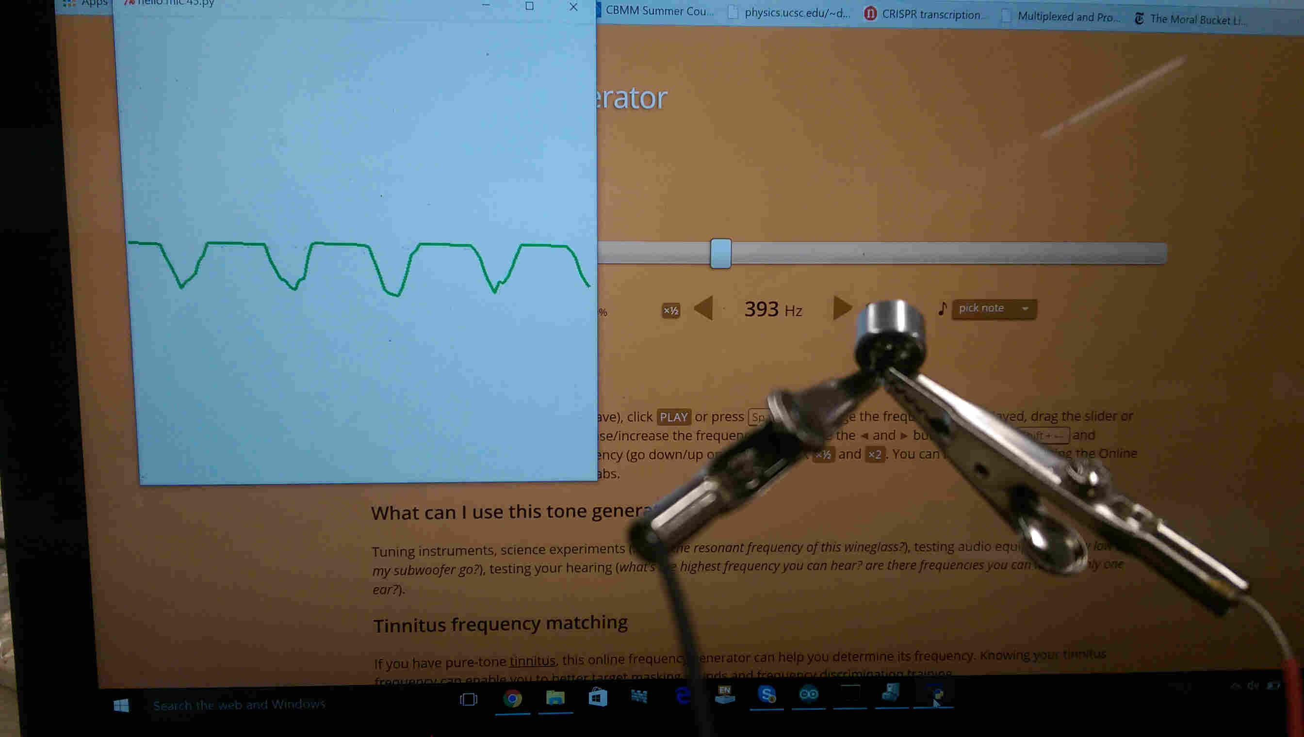
The first instance of the board, as depicted above, showed naught but noise. After fiddling poking around, remaking the board, and *liberally* resoldering the electret mic leads, I managed to get something response to audio input. However, there was a strange thresholding affect wherein the positive deflections did not seem to register. Poking around the op-amp, the voltages seemed to be sitting in the right places, so I wasn't sure what the problem was
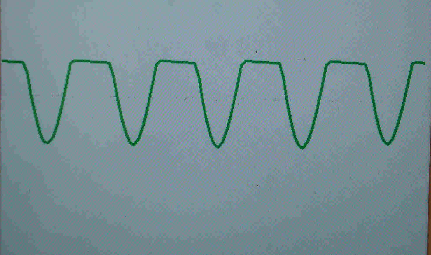
the board can detect a pure tone cleanly, with a weird threshholding affect
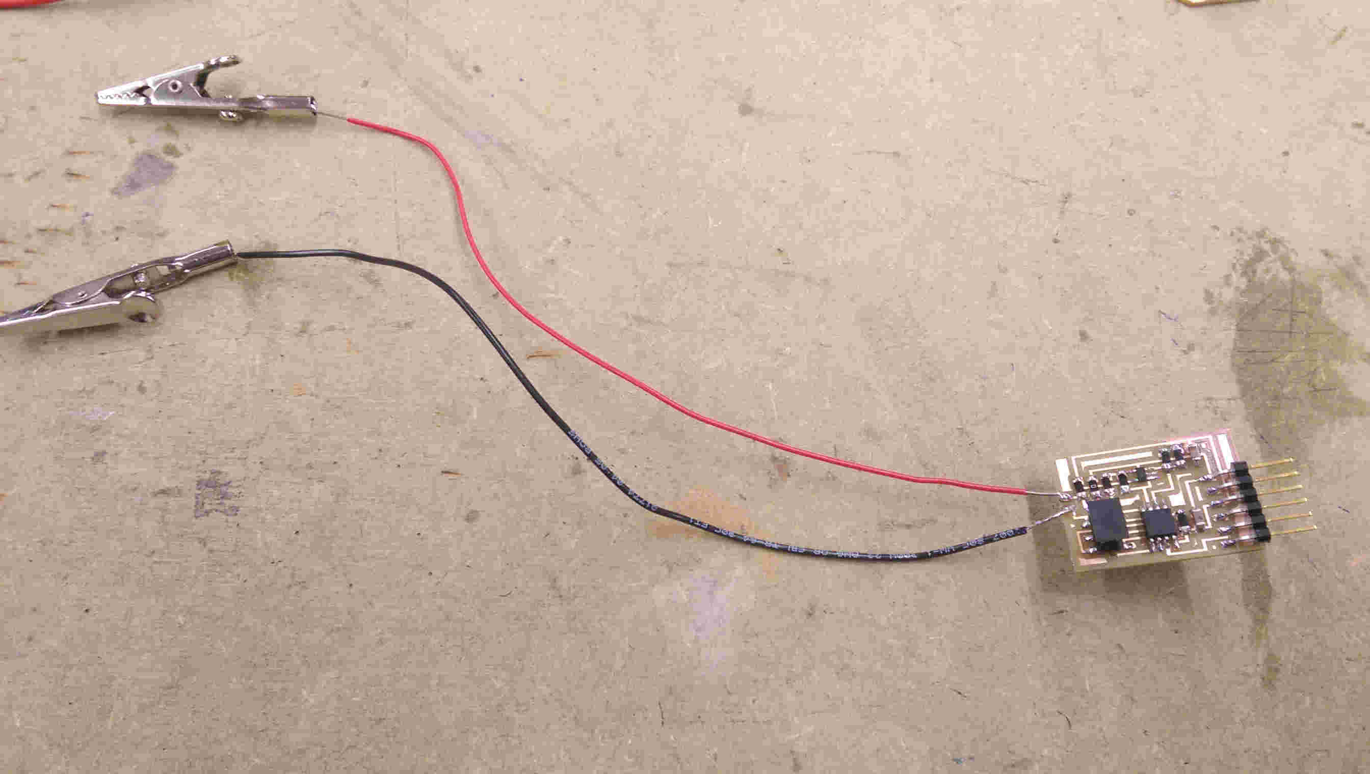
attaching leads to the board
with the alligator clip leads, the mic can still detect a signal...
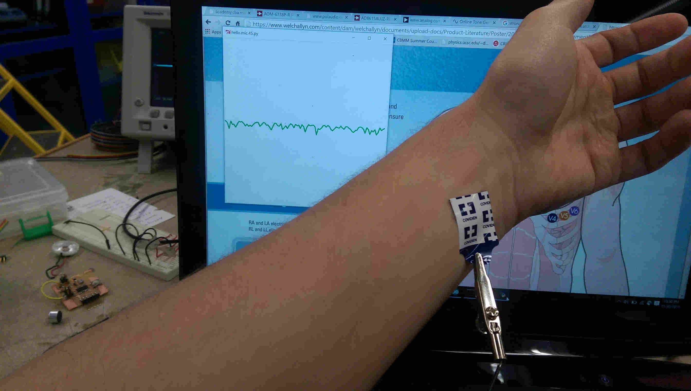
...but the skin electrodes cannot
Undaunted, I moved on to see whether the mic would still read when attached to alligator clip leads. Somewhat surprisingly (to me at least), it still worked well. Attaching the Ag-AgCl electrodes to my wrist, however, didn't register a singal deflection from my pulse. I contemplated attaching the electrodes to do a proper electrocardiogram, but decided it would be prudent to wait until I had thought through my electronics before attaching them across my heart (considering a successful detection might require active electrodes with on-electrode op-amps).
step response measurement
The other input modality I played with this week was the step response test. In its most basic form, this words by tying an A-to-D input between a large ( ~MOhm) resistor and a capacitive load, and charging the capacictor through the resistor with a seperate output-configured "charge" pin. By waiting a set amount after the charge pulse, we can sample the exponential charging (or discharging) of the capacitor and detect changes in the load capacitance.
For this first experiment, I went with a simple single 'plate' load, rather than a two-plate Tx/Rx configuration. Porting the ATTiny45 code to the ATTiny44 was simple enough, and mainly involved reconfiguring the pins.
In order to configure the ADC to work properly, the ADMUX bits need to be configured as desired in the setup portion of the code. There are slight differences between the 45 and 44; the one-byte register on the 45 has pins REFS[2:0] for mode configuration, ADLAR for controllign left/right adjusted reads, and MUX[3:0] for ADC pin selection. For the 44, there are REFS[1:0] and MUX[5:0], due to the larger number of available pins for A-to-D.
The microcontroller code samples the step response at 1, 10, and 100 microseconds timepoints, both during charging and dischargning, then sends those bytes to python through the FTDI. Python then averages each time step over the charge and discharge phase, and displays the result.
first board; designed to output to an audio pinout via an H-bridge, but failed
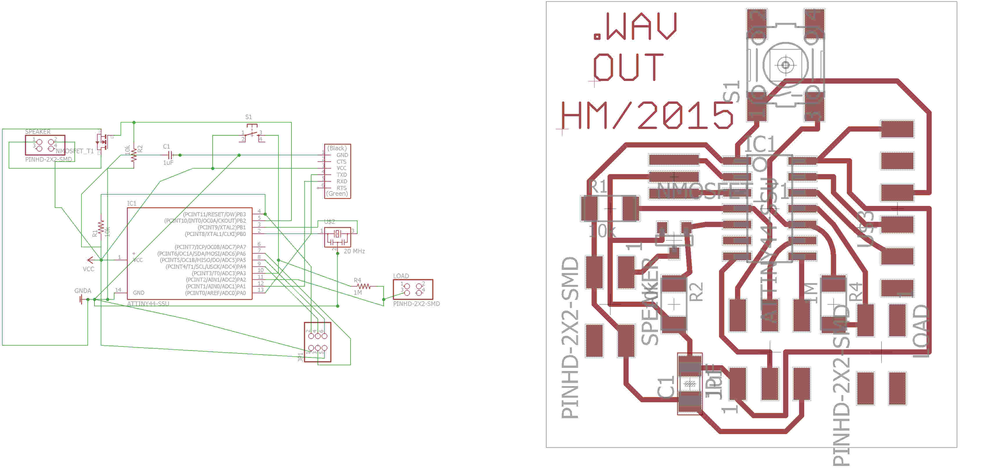
design for eventually successful board
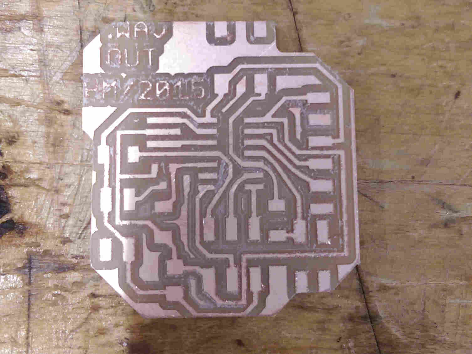
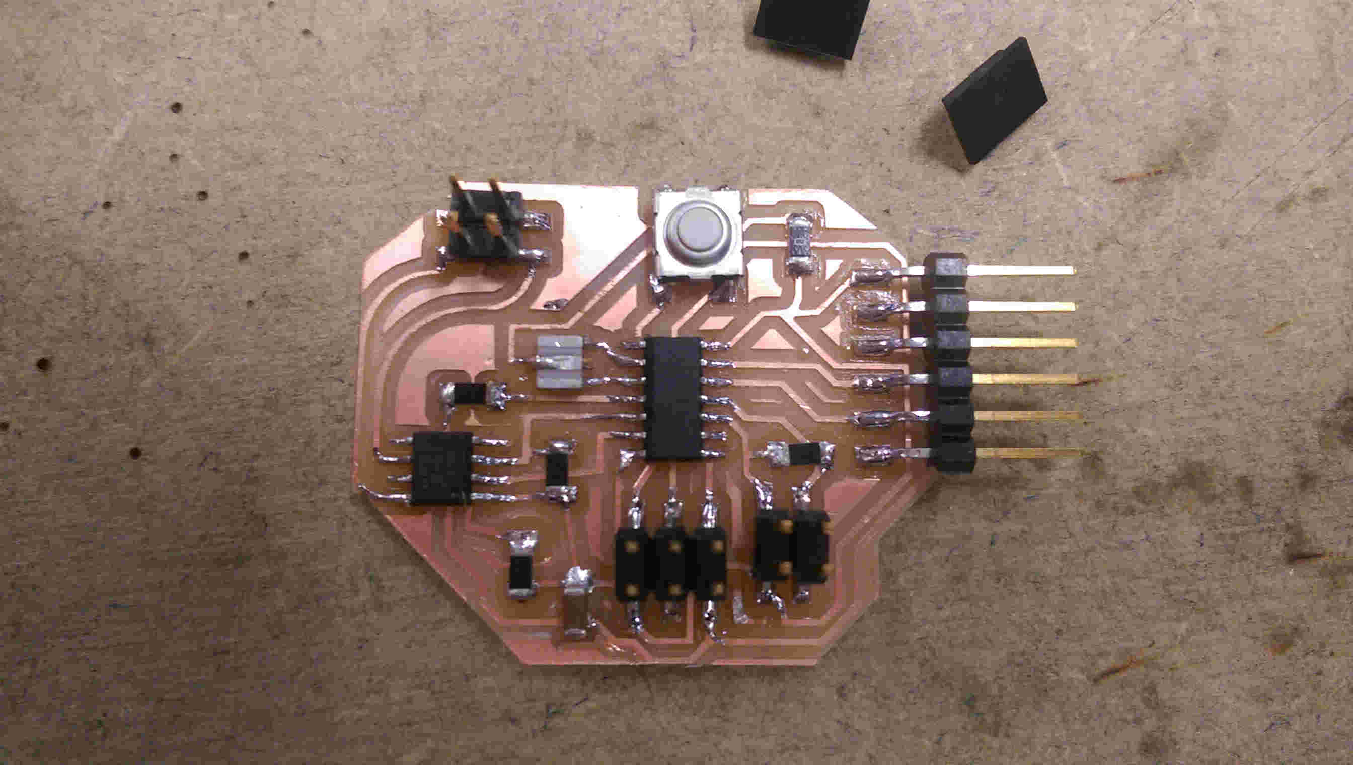
traces for second board; now driving audio in one direction via an N-MOSFET
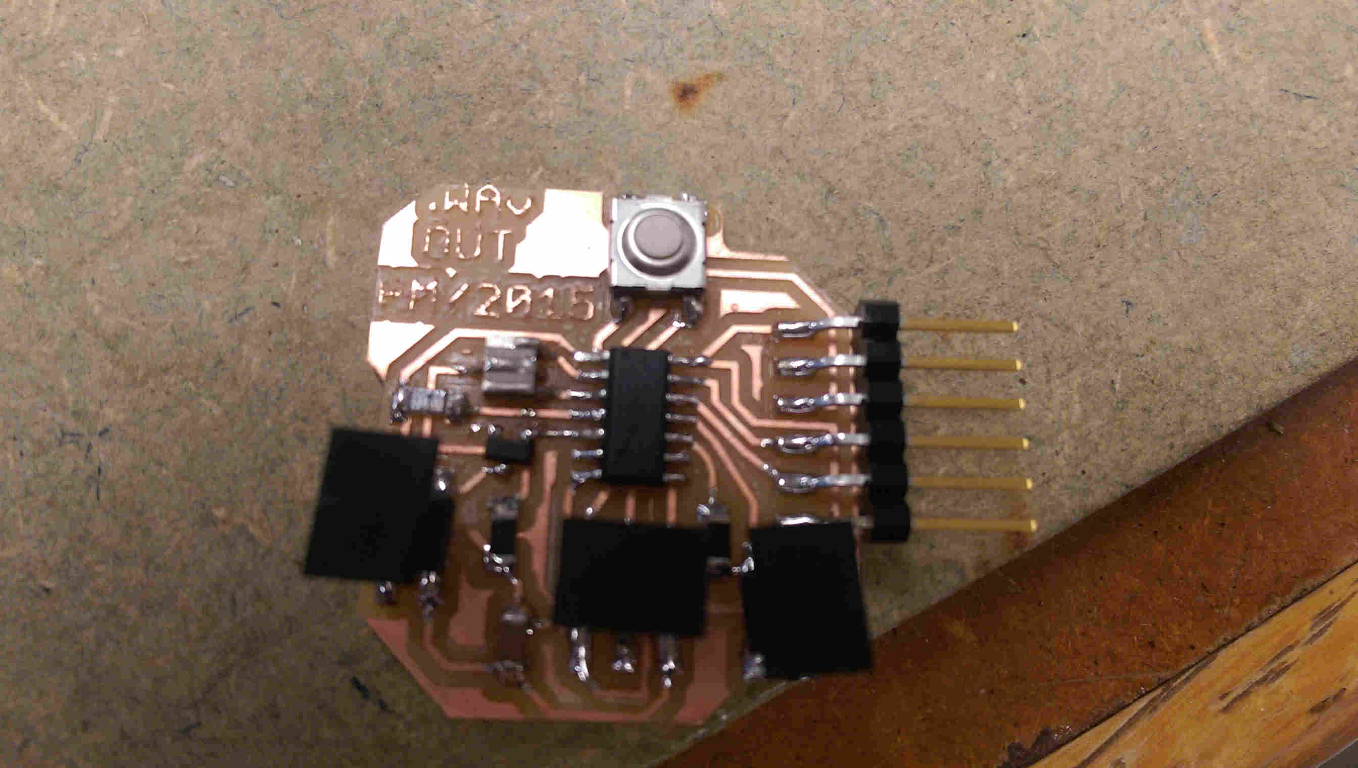
board 2 stuffed...
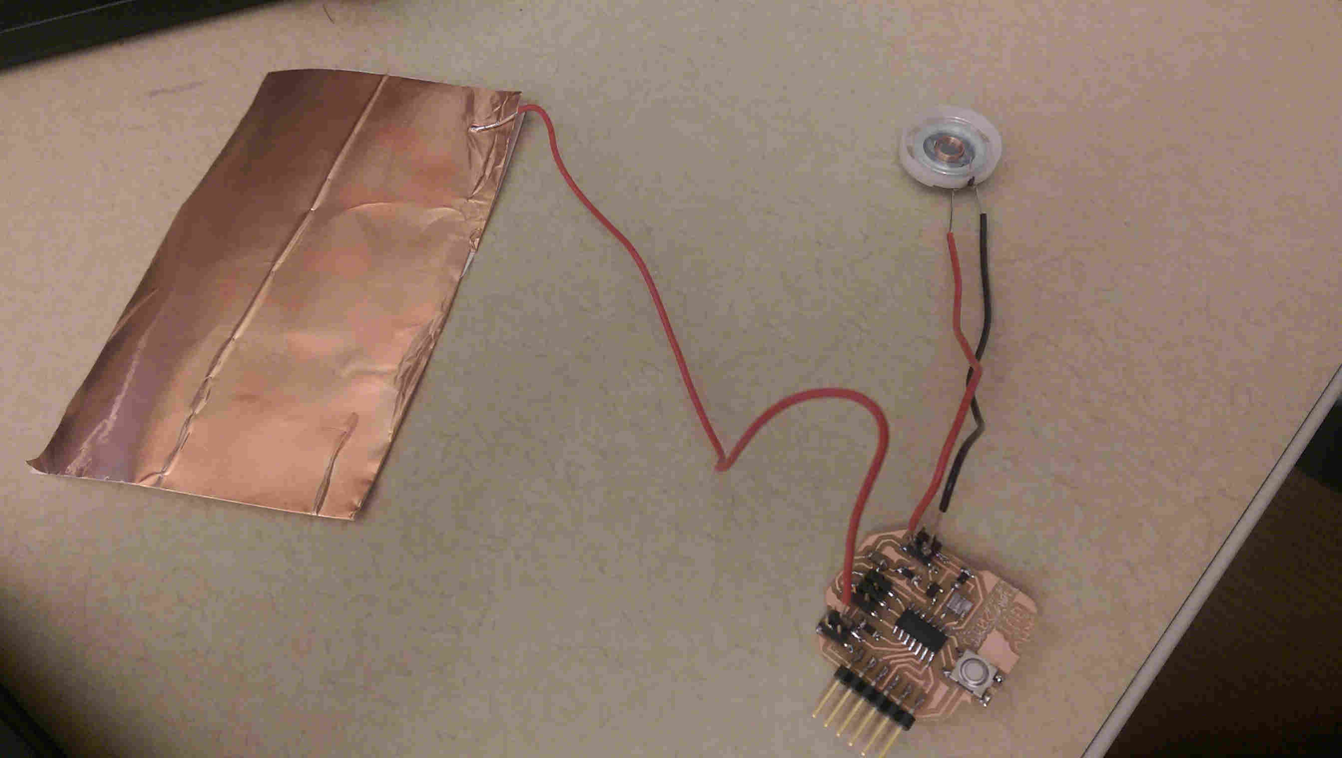
...and with capacitive load and speaker connected
testing load input sensing
The capacitive load input worked as tested for both boards above; my original goal had been to improve upon last weeks output by driving the speaker bi-directionally through an H-Bridge. However, I had some trouble getting the H-bridge output to work properly - I placed inverted PWM inputs on the two input terminals, with both Vref and VBB connected to my 5V source, as well as LSS and the ground pin grounded. But both output pins seemed to stay high, irrespective of my inputs.
With time constraints being as they are, I decided to adapt the basic design from last week to take the 10 us capacitive load, divide it by 4 (i.e. by bitshifing the 10-bit value by << 2) and then set it as the ORC0A output value to control the audio output.