Week 11 Output Device (Images need to be uploaded)

This week we are supposed to add an output device to a microcontroller
board we've designed and program it to do something.
Since my final project will rely on motors, I chose to try out a DC motor first.
Data Sheet
 As I did not make any boards in week 9 (input device), at first I planned to continue working on the
Fabkit I/O I milled two weeks ago. However, before soldering the components I found out that it is
using ATmega168 which I could not find in the stock of the shop. Then Neil's answer to the email sent
by Yuval reminded me that there is an Arduino variant in the
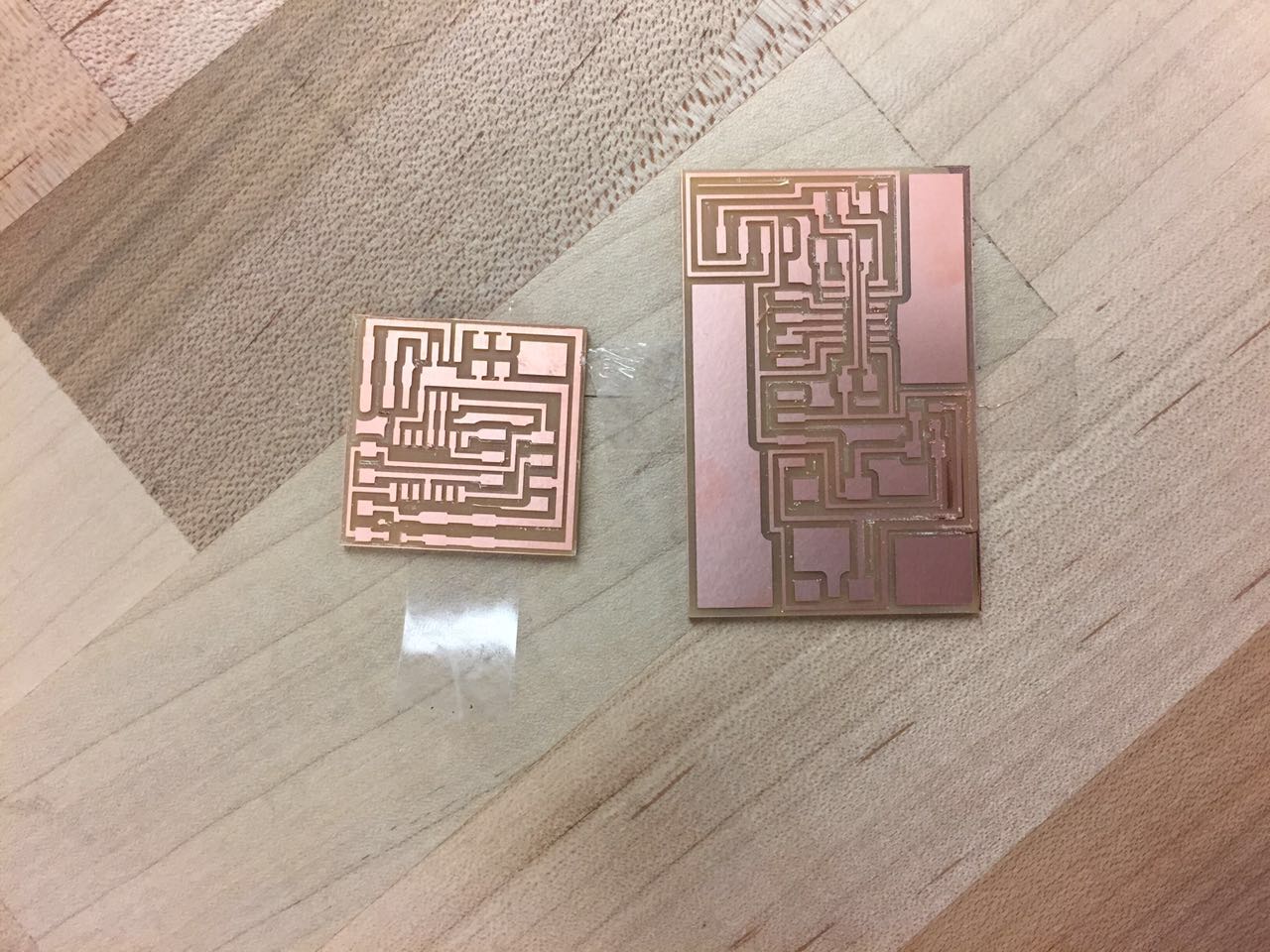
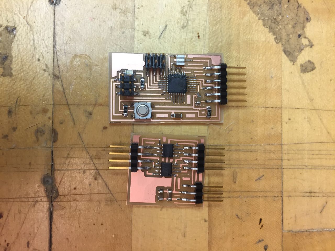
embedded programming page. Thus I turned to made the hello.arduino.328P board.
As I did not make any boards in week 9 (input device), at first I planned to continue working on the
Fabkit I/O I milled two weeks ago. However, before soldering the components I found out that it is
using ATmega168 which I could not find in the stock of the shop. Then Neil's answer to the email sent
by Yuval reminded me that there is an Arduino variant in the
embedded programming page. Thus I turned to made the hello.arduino.328P board.
 I also made a separate H-bridge board for controlling the DC motor.
 Simply speaking H-bridge is used to revert the direction of DC motor by changing the direction of voltage.
The advantages of separating the boards are I could easily reuse them or modify the pins later for my final project, and I could supply a 9V battery separately to the DC motor without adding a 5v voltage regulator.
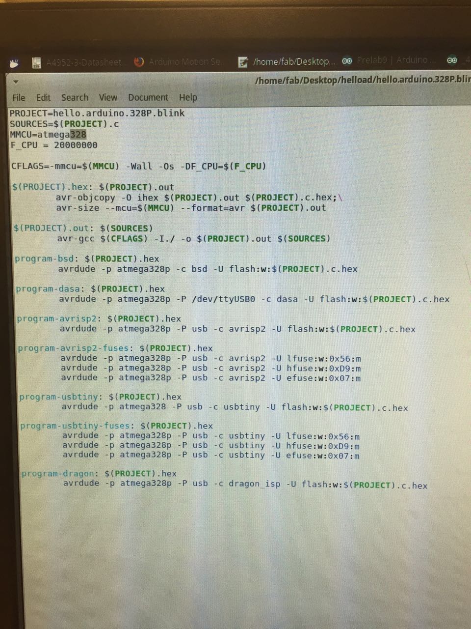
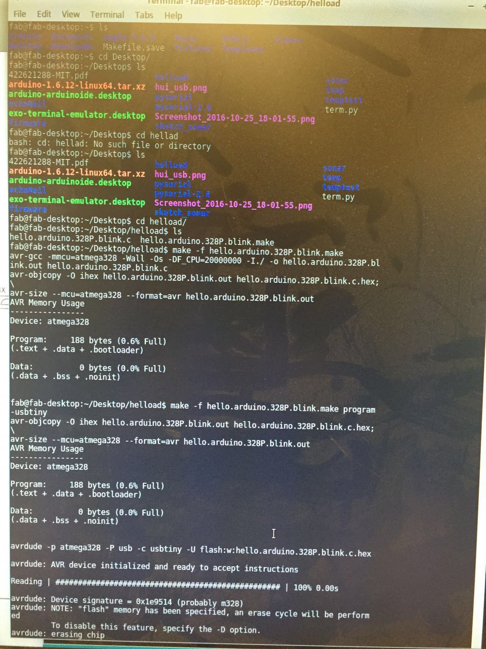
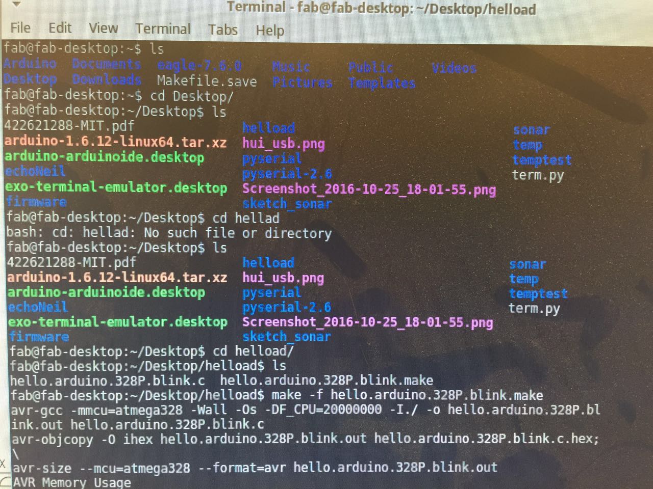
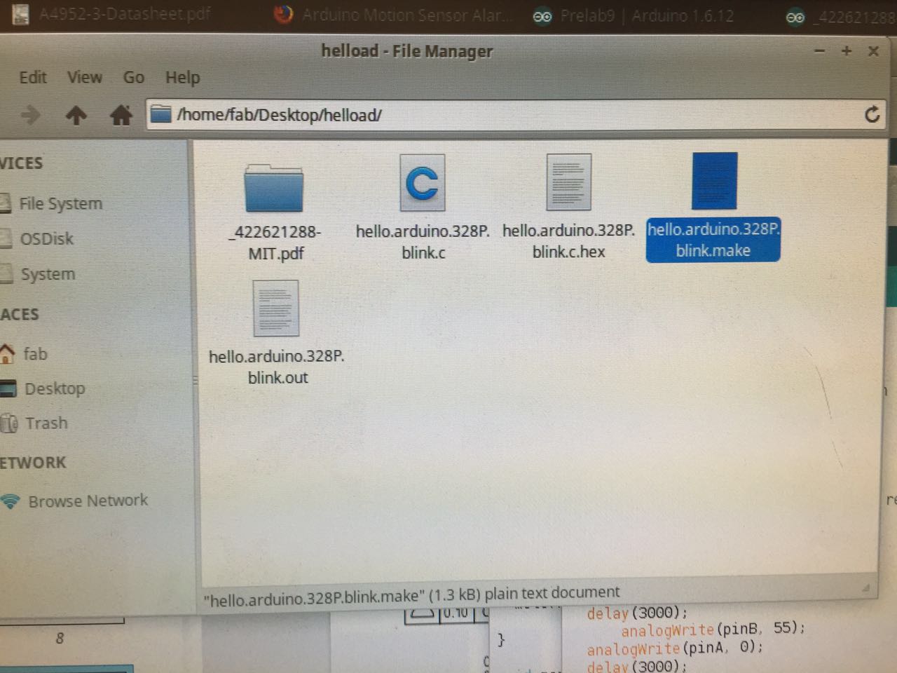
After finishing the board, I met the problem of failing in uploading the test blink code to the board. It took me quite some time to realize that the microcontroller on my board is ATmega328 instead of ATmega328P. They are in the same drawer and the labels are so tiny that it's easy to be mistaken. The LED started to blink once I changed the board setting, but the blinking pace is much slower than expected. I tried to link the controller board, H-bridge board, 9V battery and the DC motor, on a breadboard but it did not work.
After several rounds of attempt and failure, I decided to mill Neil's DC motor board then for at least getting the motor run. Just at the moment I was about to start soldering Calvin came in and asked whether I need help. He helped me to realize that I forgot to burn the bootloader. There are errors reported when burning the bootloader through Arduino IDE, thus Calvin used the Avrdude to make file in terminal and it finally worked properly. Ah before making file he changed the "MMCU" from "atmega328P" to "atmega328" in the making file.
 The second mistake I've made is I chose PB1 & PB2 to be the output,
but PB1 is not a PWM output pin in Atmega328 (it is PWM in Atmega328P, I looked at the wrong page of the datasheet in the previous day).
So we change to PD5 & PD6, which are pin 5 & 6 in Arduino, to be the outputs for controlling the DC motor.
The second mistake I've made is I chose PB1 & PB2 to be the output,
but PB1 is not a PWM output pin in Atmega328 (it is PWM in Atmega328P, I looked at the wrong page of the datasheet in the previous day).
So we change to PD5 & PD6, which are pin 5 & 6 in Arduino, to be the outputs for controlling the DC motor. Eventually, it worked!! Calvin you are the best!
Add Input
Next step is to add some input to control the motor. I took a PIR motion sensor and linked it to PB2 (pin 10). A piece of test code was written to lit the led once a movement is detected. It seemed like working somehow but the signal is relatively unstable. When I touched the wires of the sensor the led will on, I may need a better environment to further working on my testing later on. Now I just hook the sensor and motor together to create a rough interaction.(*Update: the reason for the unstalbeness is because that this IR motion sensor will measure all infrared light radiating from the objects in its field. Since the light was bright in the shop this environment will blind(or dumb) the sensor sometims. It worked well in a relatively quiet and dark environment.)