Week 11: Output Devices
This week was an interesting week, we had to do a board that would essentially control an output device. I decided to build upon the motor controller board, seeing as I will use it for the final project. I also tried doing an LED array, but that is still in the works.
Initial Attempts/Fails
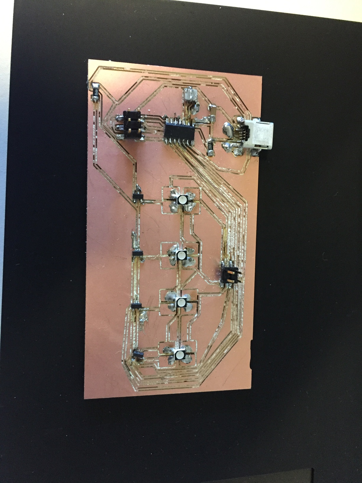
I started by trying to design an LED array that I could use for my final project. Although the design seemed OK,
the routing was hard, almost impossible. After the board was finished, I decided to go and mill it. Here is where
the failures started. The first problem was that the traces that I had placed in Eagle were too small. What this did
was that when I tried to mill the board, the traces were 0.01in thick. This meant that any small mistake would
rip a trace out almost entirely.
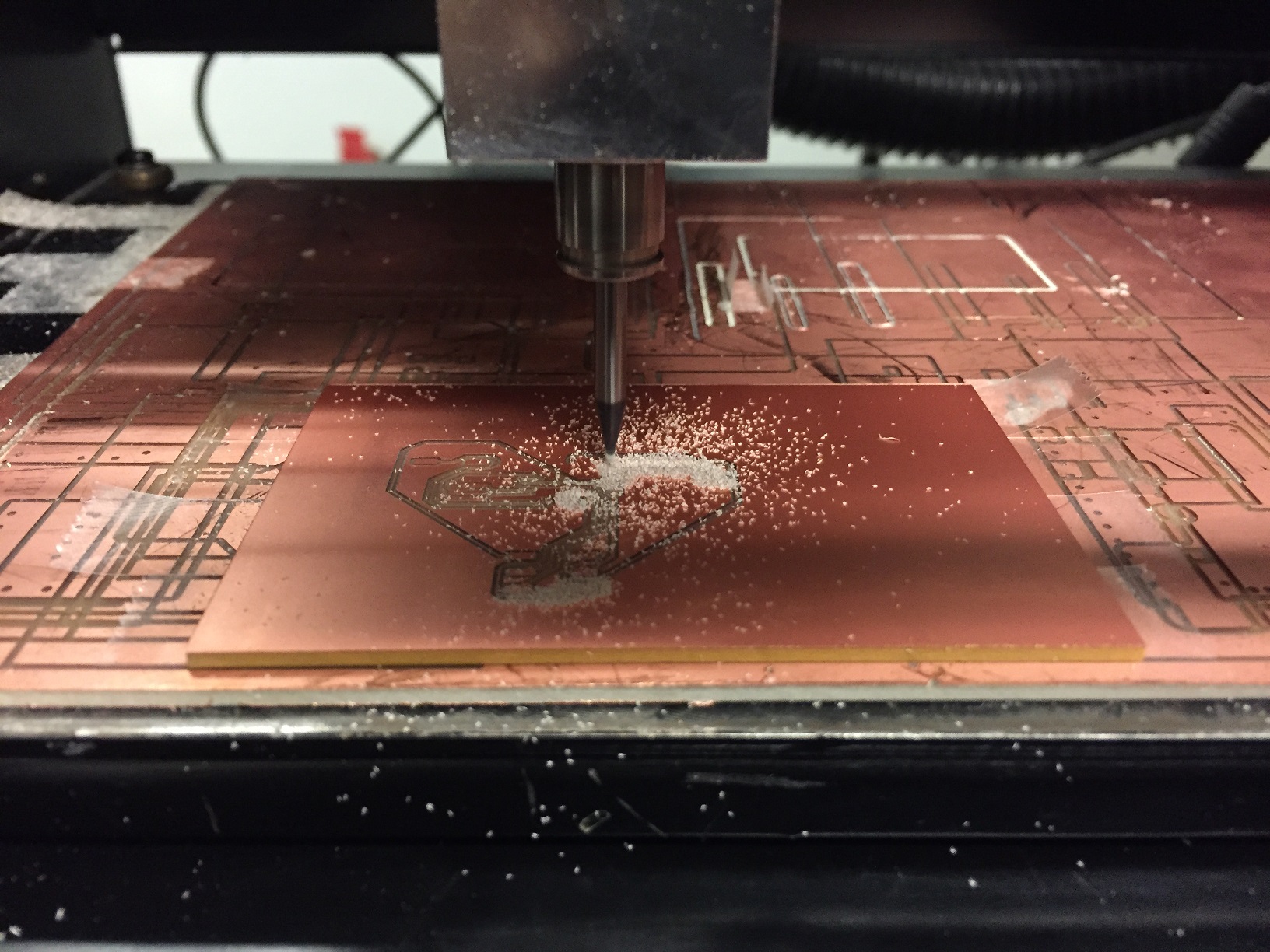
Milling and ripping
Adding to this, I used an ATMega in my design. The pins on the ATMega are just barely larger than the traces that were 0.01in thick. This meant that some of the pin traces of the ATMega were destroyed during milling. Another failure here was that the board that I designed was larger than the 3x2in copper plate that we were dealing with. To overcome this, I used some of the copper boards that were around and cut them to much larger dimensions.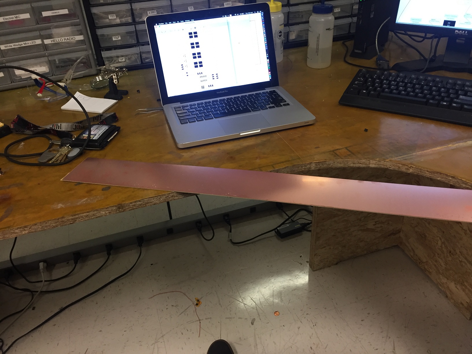
Larger Copper Board that I cut
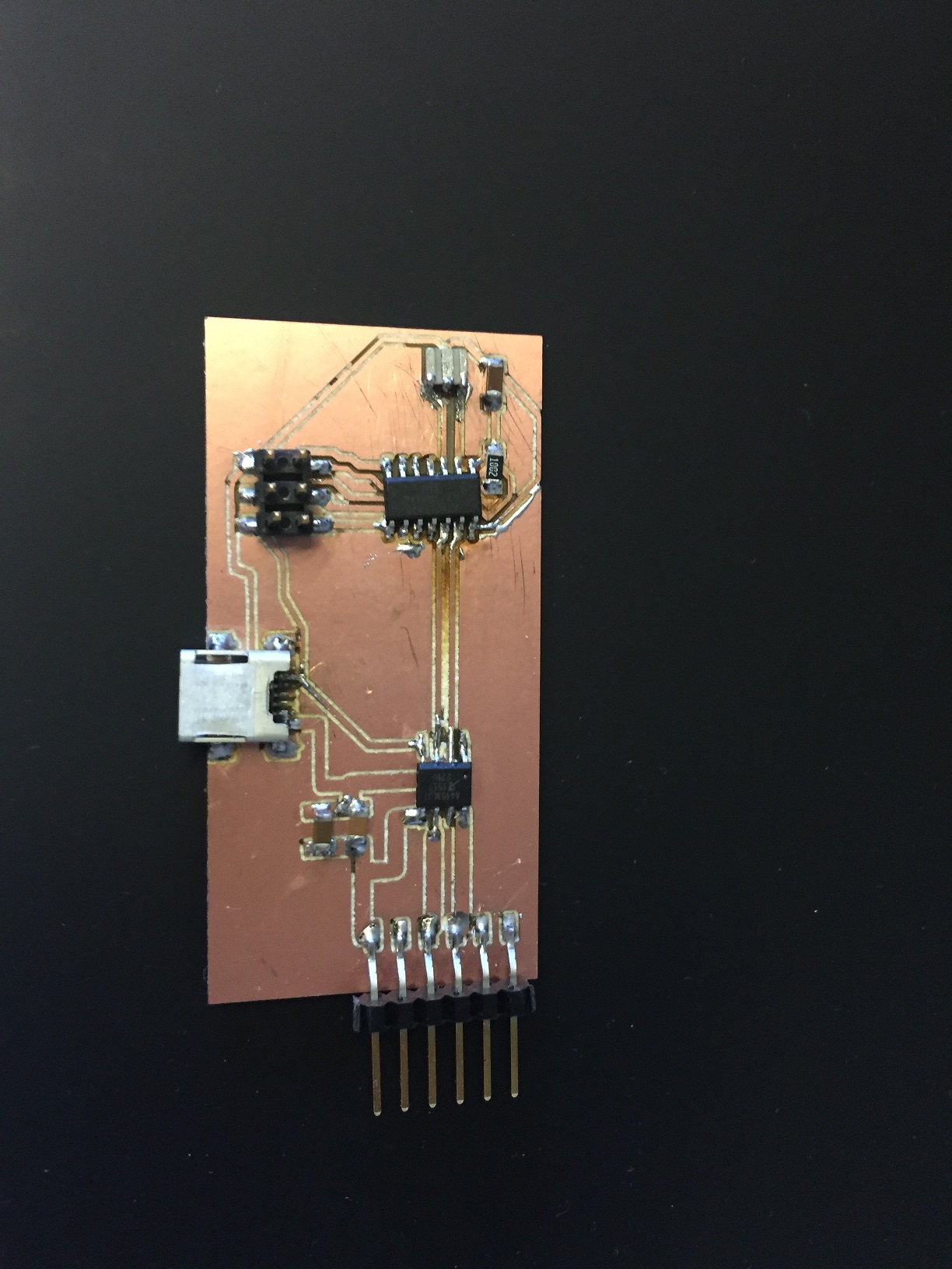
Continuing with the fails, I decided to redesign the board in order to separate the ATMega, which would be the board's controller, the LED strip into LED rows, and a circuit to be able to connect them all together. After designing the 3 boards, I milled them and realized that I had messed up the VCC connections, and that it was not going to work. I gave up on these boards for the time being, and decided to move on to the motor controller board that I would eventually need. Also, when I was designing the board, I learned that the capacitor and the resistor to the power supply are necessary for safety and programmer reasons. If the resistor is not connected from MOSI to VCC, then the programmer will not be able to work correctly. Additionally, if there are any sort of irregularities in the power supply to the ATTiny, the capacitor will filter them out.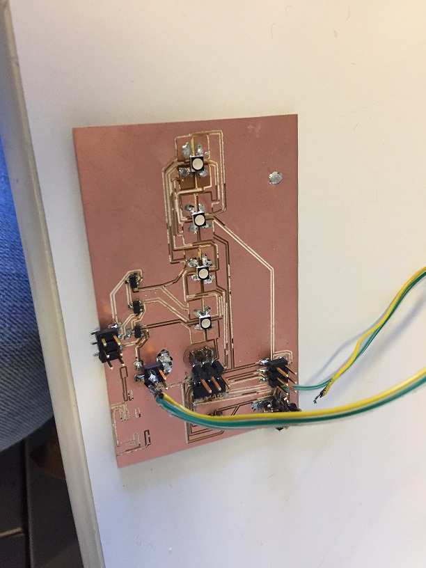
Failed boards
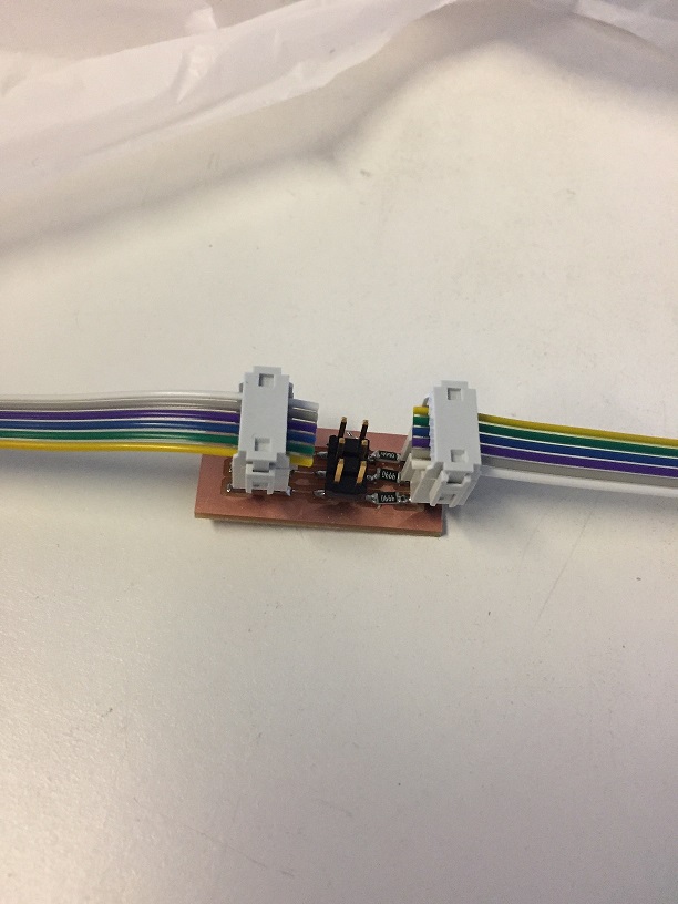
The Motor Controller Board
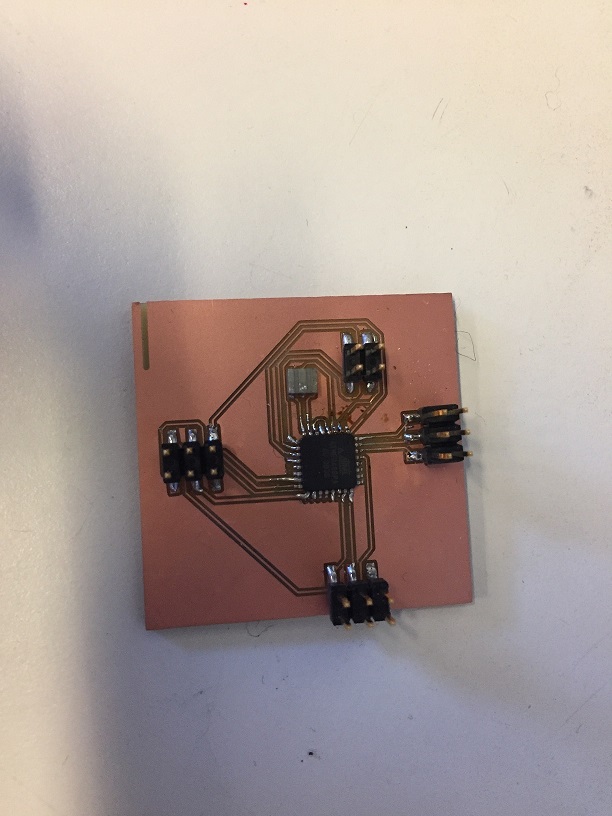
Now came the other set of fails, but eventually a success. The Motor Controller board took me 5 attempts. The first attempt was realizing that I forgot the capacitor and the resistor to enable the programming on the ATTiny. The next 2 attempts were because I had not realized that I had damaged the resonators. Apparently, if you use the heat gun to place the resonator, it is possible to damage it completely and irreversibly. I realized this was the problem, because when I tried setting the fuses on the ATTiny, it would work the first time, and never again. I looked online, and eventually found that the problem was that the Tiny was waiting for the resonator. I desoldered the resonator and hand soldered a new one, and it worked perfectly. However, I had to redo the board, as I had some problems with the connection of the H-Bridge. I had connected most of the pins of the H-Bridge correctly except the ground and the LSS pin. The ground I had assumed that it was the same ground as the VBB. This was wrong, it was the ground of the Tiny. The other problem was that I thought the LSS pin was optional. This was also wrong. It had to be connected to the ground of the H-Bridge along with some capacitors for the VBB. Once I realized this, I managed to get the board working. It was also important to note that the H-Bridge operated on 8+V on VBB.
Working motorcontroller
The Proof
Pro Tips
Here are some of the things that I realized throughout the campaign
- Check for shorts
- If the PSU voltage is not the same when it is powered on, there is likely to be a short
- Never skip out on putting the reference design things (capacitors, resistors)
- Read the datasheet for the components that you use, it more than likely has the wiring configuration for the board
Prototype LED Board
Files
Here are the files that I used.