This week I decided to design a board that could control two DC motors. I've decided to focus my final project on the creation of a robot capable of locomoting across a cuboct structure using continuous rotation joints. For this, either standard DC motors or Brushless DC (BLDC) motors will be most suitable.
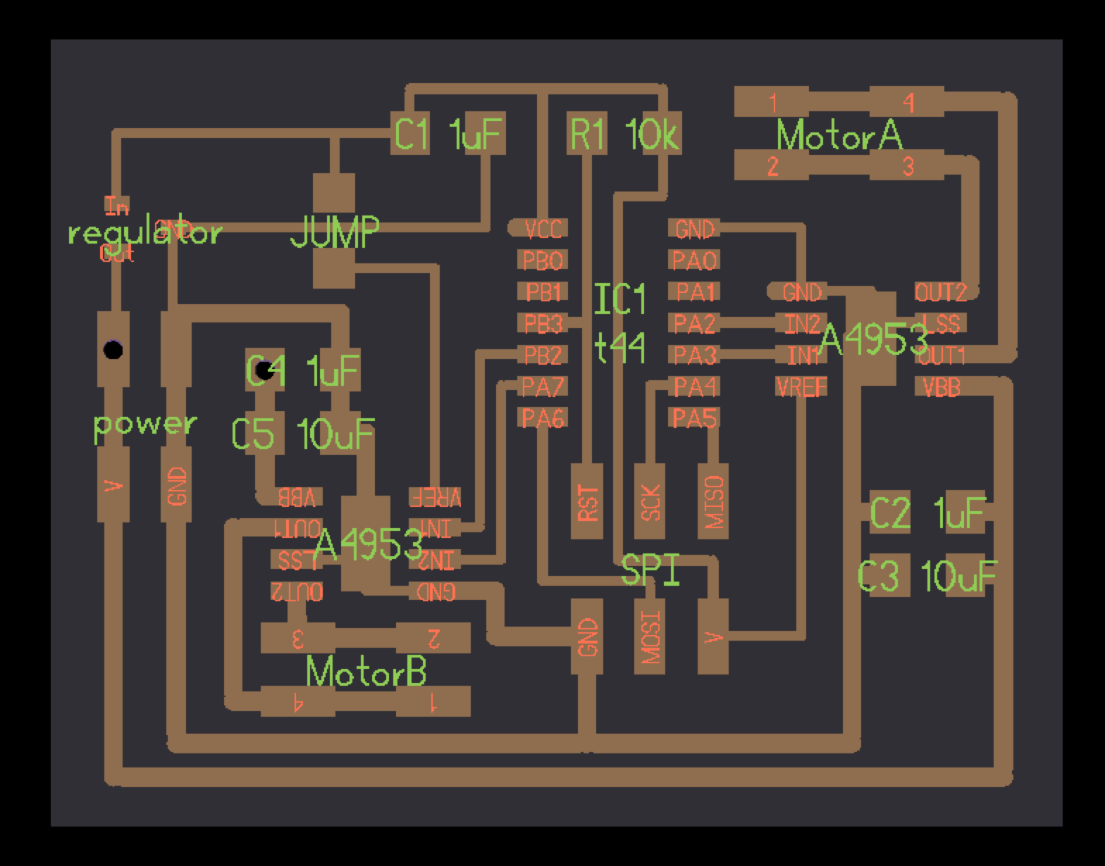
Using Kokopelli, I started out by replicating Neil's DC motor control board which uses the A4953 Full-Bridge DMOS PWM Motor Driver chip. I then extended the design by adding a second chip and the associated capacitors and connectors. I connected the input's of the second A4953 to PA7 and PB2, as they are only being used as straight forward outputs.

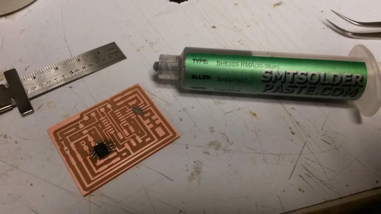
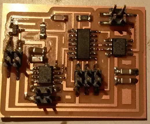
The A4953 has a ground pad on the underside of the chip. To attach this I applied solder paste to the pad and placed the chip on the board. I then soldered the pins to the board and came back the ground pad with the heat gun to melt the solder paste. I was a little worried about damaging the chip so I'm not sure whether I actually metled the paste however, measuring continuity with the multimeter indicated that a connection had been made.
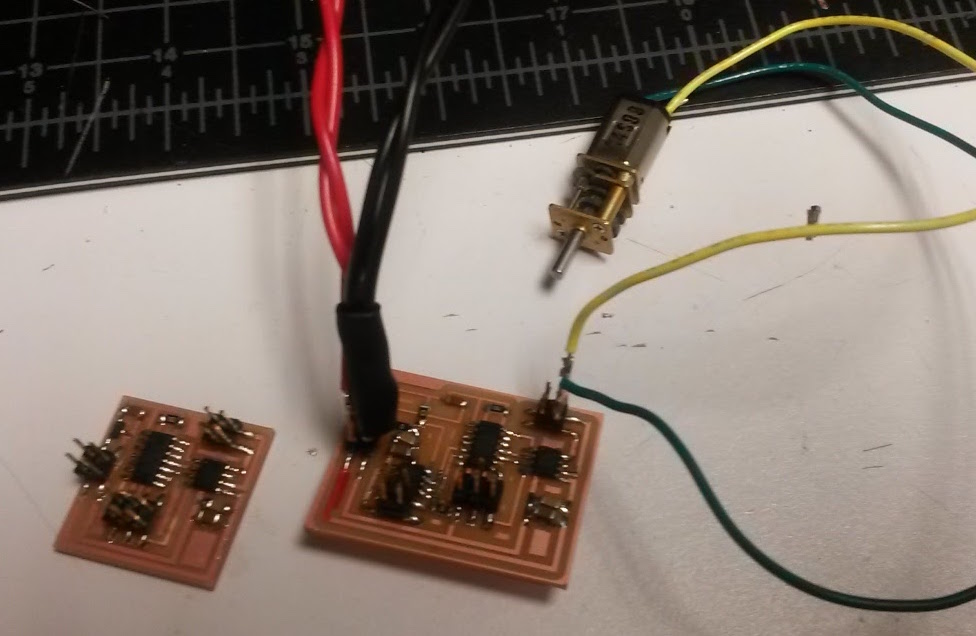
After stuffing the board I managed to connect the power the wrong way around and it started smoking. As a precaution I changed both H-bridge chips and the regulator and used a red Sharpie to mark the V+ pins. I altered the code to account for the second H-bridge and also the fact that I was using a pin on port B. I uploaded it OK but when I connected a DC motor nothing happened. The ATTiny seemed to be working OK as when I measured the voltage of the output pins PA2 and PA3, their voltage was moving up and down as instructed by the code. When measuring the voltage across the output of the H-bridge chips I didn't detect any changes.
I looked at the output of the ATTiny on an oscilliscope and saw that the inputs to the A4953 were moving between 5.3V and 0V which exceeds the minimum range required for the H-bridge chip of 0.8 - 2V in the data sheet. At this point I thought it might be something to do with my redesign, therefore as a sanity check I fabricated and stuffed the initial design using the trace and cutout .png supplied by Neil. Then Pedro told me that VBB of the H-bridge needs to be at least 8V. After increasing the voltage from the power supply the motor started moving. And when I went back to my initial redesigned board, it worked too!