Final Project: Dynamic Light Sculpture
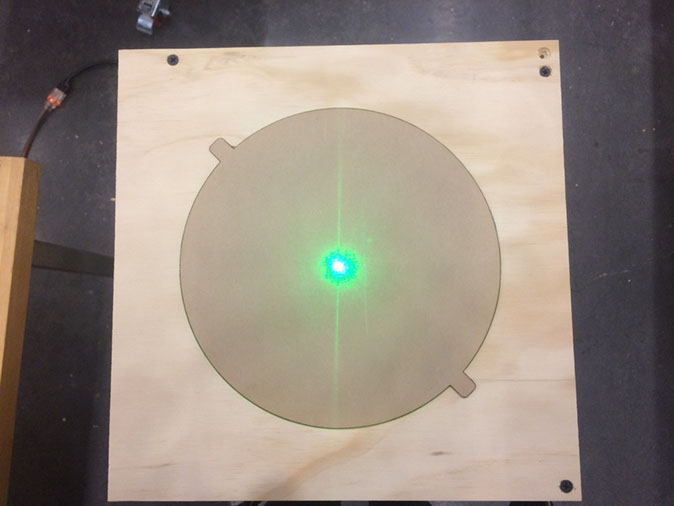
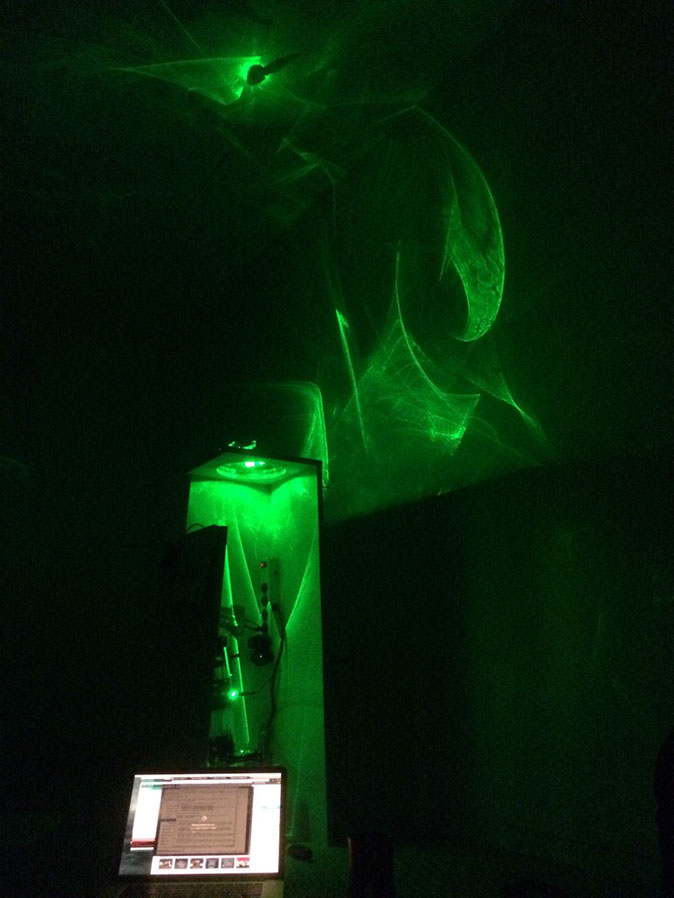
I intend to make dynamic light sculpture installation pieces for my final project. The pedestal design above will function as a shell for the optical and electrical system that control the path of a laser beam and as a surface to place glass sculptures. The glass sculpture will function both as an object of interest and as a medium through which to refract, diffract, and internally reflect light.
I intend to use a stepper motor system to create a laser scanning system that has micron precision and extremely slow movement. Using this system I will program the path of the laser beam in order to control the images cast out into space by the sculpture. I'm not sure how to best design such a mechanical system to avoid backlash and prevent drift over time. I imagine I'll be employing two micrometers coupled to the gear train by a timing belt. My hope is that the elasticity of the belt coupled with a set of pulleys to step down the motors will prevent any jerkiness. As for the mirror, I hope to employ something that has two axis of freedom.
Examples of the photographic process on which this project is based off of are on my website: irradiantart.com
Part I: The Pedestal
I spent time shopping around different CAD tools this week focusing on various means for 3D parametric design. In so doing I gained some experience with the following programs before settling on Fusion 360 for my project: Solid Works, Onshape, Rhino+Grasshopper. I would have liked to focus on Solid Works but the license server functioned only intermittently for some reason.
In each program I built the same trapezoidal pedestal to learn the basics. This pedestal is intended for my final project. It will contain the electronics and optics that will light a glass sculpture that will be affixed to the top.
v1
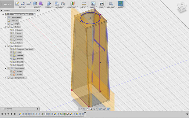

This physical pedestal mock-up came out to be 48" tall which was clearly too tall - I'll redesign it to be shorter.
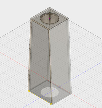
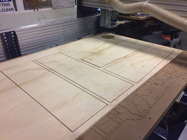
I ended up settling on 40" tall. Also, I added a lip for the acrylic to sit on. I then imported all of my parts and created toolpaths.
Note: The pocket toolpath seemed to do weird pecking so I ended up using an inlay toolpath.
v2
As i need to assemble this around all my other parts and do beam alignment - I chose not to assemble things until the very end.
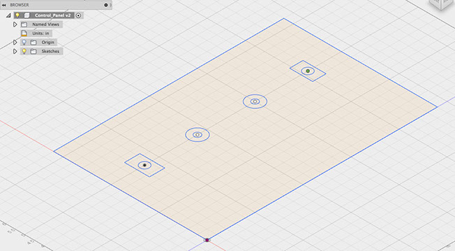
Part II: Control Panel
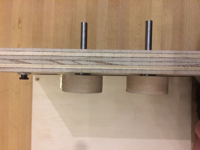
I created a design for a control that contains a, On-off-on switch, a button, and holes for which a shaft and bearings can be friction fit into. The bearings and shaft hole are for knobs that will connect to rotary encoders. The button and switch are for controlling the mode sand saving - i will implement these if I have time, all I really need are the knobs.
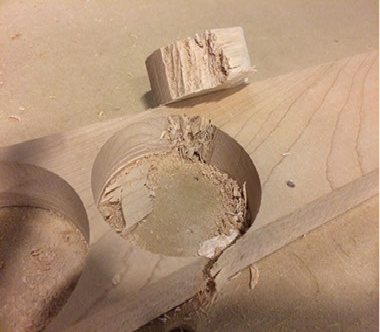
I Cut some knobs with pilot holes for the shaft out of Birch. Despite having drilled down both sides the wood vibrated at the very and and tore up the edge of one knob. After re-affixing the wood I was able to mill them out properly.
Unfortunately the holes were too small and I had to open them up on the drill press. I did a bad job and the knobs ended up lopsided.
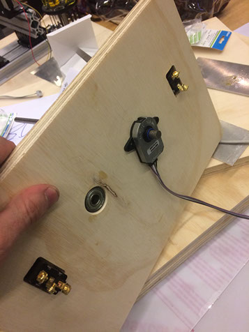
I after adding all the hardware I have plenty of space for electronics as planned.
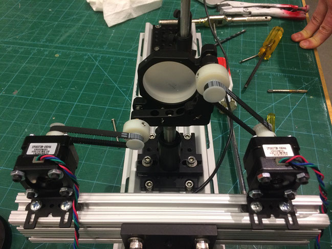
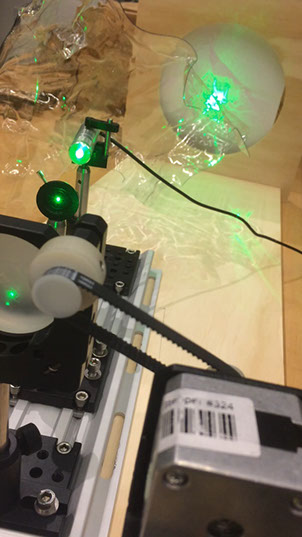
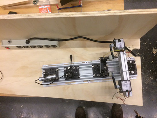
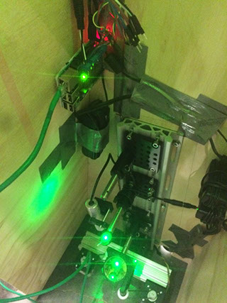
Part 3: Optics and Machine
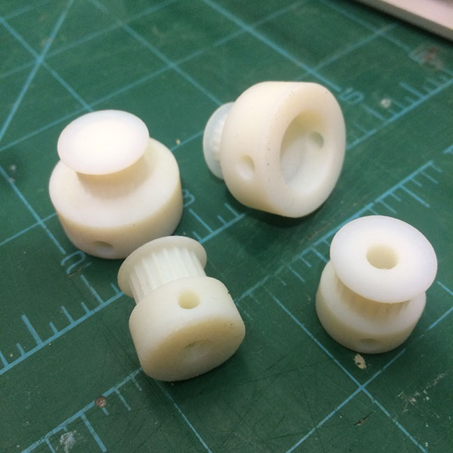
This part is the machine with stepper motors and scanning mirror. I ended up going with pulleys that interface to the back of a mirror via timing belts. Because I needed custom sizes for everything I ended up pulling tooth patterns off the Internet and creating 3D models in Fusion 360. I even made little holes for set screws that were then tapped. It worked beautifully and I got to tap my first holes!
3D prints made on the Eden.
I mounted the pulleys and steppers onto my optics and its really solid. Unfortunately when I tested out the steppers they were too weak and also would jump under load. Not to mention that they are super loud. -- the seem to jump even when not under load in only one direction, I have no idea why.
However I did manage to get them both up and running!
https://www.youtube.com/watch?v=BmuYyB3Q47I&feature=youtu.be
I ended up installing better stepper motors and this stopped the jumping. However they are still quite noisy which I do not like. I imaging that the wood is acting like a diaphragm.
Part IV: Electronics
This part was very frustrating because I got everything working independently and then after assembly most everything broke.
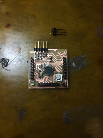
The board I made was a very minor modification of the Fabkit board which had larger pads and holes so that there would be rivets to fit my headers. The board sports a mega328P which allowed me to do some of my prototyping on an Uno and then port my code over without modification.
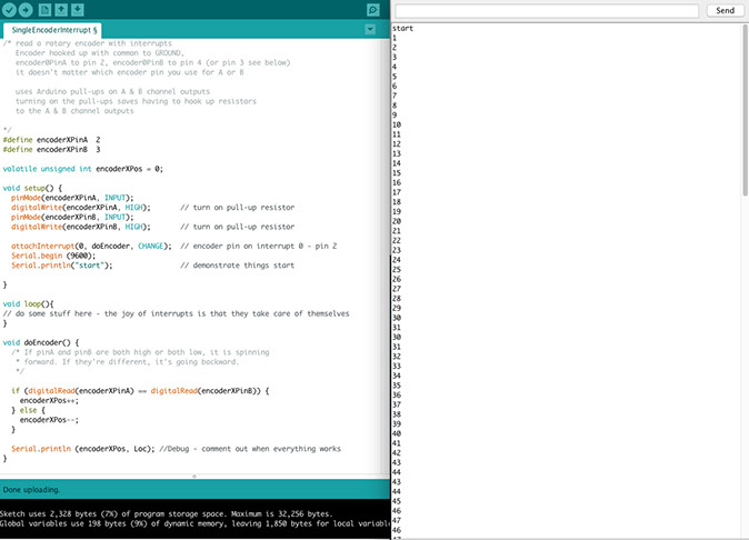
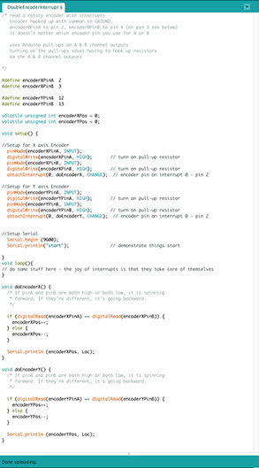
First off, when I received the encoders I made sure they worked with some bit banging code. They definitely work great and have a resolution 2048 per rotation. However, I will need to run other processes and monitor two encoders so this wont work terribly well. Instead I got code for one and then two rotary encoders working with hardware interrupts. Unfortunately, when i turned everything on again in the morning nothing worked... I think there is something weird happening with the internal pullup and setting common to 5V instead of normal ground. It appears sometimes after unplugging and replugging in encoders over and over it can get back up and running. I did get this to shoot serial over to the pi but since it was so unreliable I was never able to do anything useful with it.
To address this I tried an encoder library but it was even worse and often couldn't tell which way the encoder was turning. If I moved it just slow enough then sometimes it would work.
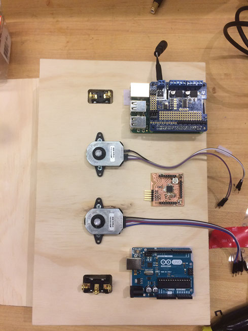
On the raspberry pi side of things - I set the pi up with a static IP address so that I could access it on my home network over wifi easily. Even so it appears to struggle getting out to the internet. Oddly enough, I can load web pages using a browser and http but could not ping google. When I leave my home network the static IP that the pi has makes it very easy to interface with using a network cable run directly from my computer. It was trivially easy to get the pi to see the serial connection from the mega328P using one of the FTDI cables.
Attached to the Rasberry Pi I got a motor driver which had a built in PWM and H-bridges. The library I used communicated over I2C with to the driver to generate a sinusoidal pattern allowing for 1/16 microstepping of the motors. To enable the 1/16 stepping I had to go into the library files and alter the number of elements in the sinusoid to get more than 1/8 stepping. This ended up being essential to provide a smooth motion of the laser.
Pi Justifaction: the goal of this project it to be able to program toolpaths on the fly in order to curate an exhibit experience. As such, I needed something easy to interface with from my computer and which could source meant locations and vectors which would exceed the memory limit of most ucontrollers.
Part V: Some Assembly Required
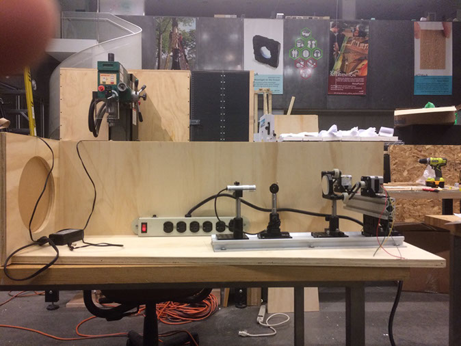
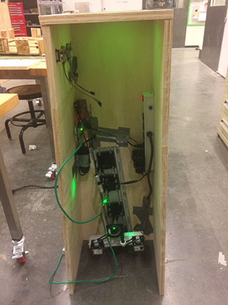
Sadly after transport assembly etc. only one stepper motor worked... but it still looks cool!
In hind site it was a bad idea to go with the pedestal form factor. It cuts the room in half. When I make a final version I'll have the sculpture mounted in the middle of the room and the optics/mechanics/electronics all off to one side scanning the laser from afar. This should allow the light to engage the entire space.
Final Questions not addressed:
who's done what beforehand?
This project has be in a light painting process I developed over 6 years ago. To my knowledge nobody else has done this. The project has relates to the practices of experimental photographers of the early twentieth century but employs coherent light.
what materials and components were used?
I used Plywood, Birch wood, 3D printed pulleys, Timing Belts, Many aluminum parts for the optics, a 35mW green laser, rotary encoders, Rasberry Pi, Mega328P, Stepper Motor Drivers, Ball bearings, Steel rod.
where did they come from?
I bought most of this stuff or had it at home in my studio space. vendors are everything from amazon, home depot, You-do-it , digikey, and thorlabs.
how much did they cost?
In total I may have spent ~200$ but the true cost including stuff I already had would be much more. Even so, it is substantially under my budget of 2K which leaves plenty for the next iteration.
what parts and systems were made?
I made the pulleys and all teh wood parts as well as a Mega328P board which didn't end up getting incorporated at the very end.
what processes were used?
CNC milling, Lathe, Woodworking, CAD design, 3D printing, laser cutting, Electronics milling and embedded programming, I2C, Serial, RJ45, Wireless, Hardware interrupts, Python, Arduino Code, etc.
what questions were answered?
I learned that the pedestal is the wrong answer as it doesn't engage the entire space. Instead the platform casts a shadow on the lower half of the room. My next iteration with have the sculpture in the middle of the room and the laser source in a container above or off to one side of the installation space.
how was it evaluated?
Aesthetically
what are the implications?
As an art piece, this work pushes the boundaries of what has been done aesthetically with light. It is part of an ongoing artistic exploration of mine that has taken over seven years and has been seen in gallery shows, art videos, and auctions. I hope to take what I learned from making this class to polish off this project so that it may be exhibited in galleries and museums.