To check that the config file included relevant information for the class repos, I learned the command open -a TextMate ~/.ssh/config, to open the config file in TextMate from Terminal.
I have not before created a cool website! I am working on a cool website, but it is still quite a mess. I started with an online template, but the CSS file was enormous and my efforts to understand the code by incrementally tweaking it were not efficient. So this week I have the minimalist look, and will add CSS features in future.
I love biology, and I recently saw a beautiful and interactive representation of the Tree of Life from EMBL. Similar to what Darwin conceptualized! I decided to turn the image into a sticker for my computer. I thought the narrow spaces between lines would be good practice weeding, and the different colors corresponding to bacteria, archaea, and eukaryota would be good practice using alignment marks as recommended by Tom Lutz.
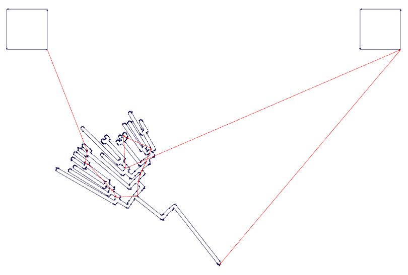
I arranged the image and exported from the website as an SVG, and then I altered the line thickness and created three separate files, one for each kingdom, within Illustrator. Then I exported these files as PNGs with 300 PPI.
Next, I used Fab Modules to convert the PNG images into SVG outlines. The PNG images were 300 DPI and 217 mm wide. I first calculated the outlines with the default settings:
The result displayed as:
Next, I loaded the SVG into CorelDRAW X4 on the computer connected to the Roland CAMM-1 vinyl cutter. Tom Lutz helped a ton and recommended to watch out for overlapping paths. Sometimes, functions will generate multiple copies of paths atop paths, which prompts the machine to cut the same path more than once, which can be bad. For example, on the vinyl cutter, overlapping paths can cause the vinyl to prematurely peel from the backing. On the laser cutter, they can give unpredictable cuts and can even start a fire! So good to watch out.
Thus in CorelDRAW we converted the object to an outline, then breaked the curve apart, then chose no fill and hairline outline.
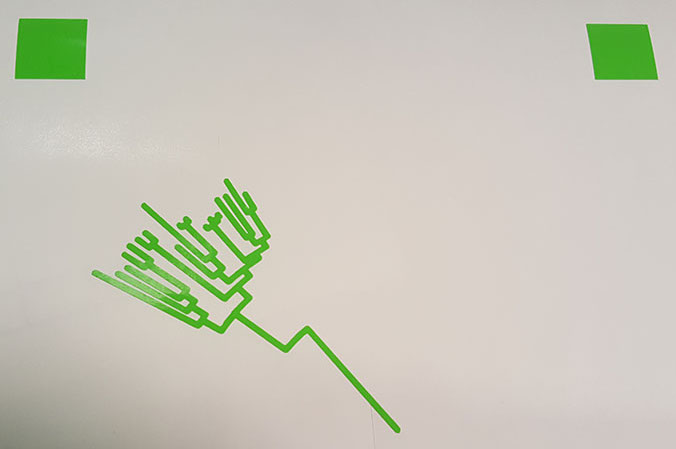
Next, I loaded the material onto the vinyl cutter. I made sure the edges of the vinyl were parallel to the lines on the vinyl cutter. For best results, best not to be stingy with material. Then, I chose Piece rather than Roll, and the machine automatically determined the size of the material: 338 mm by 154 mm. I set this to the page size in CorelDRAW and also used the Get from Machine button in the Print Properties to inform the printer driver the page size. To increase the cutting speed from 2 cm/sec to 20 cm/sec, I choose a setting in the Settings tab. I also checked the blade was just barely exposed and I set the force to 130 gf. I was quite amazed how quickly the machine cuts the complex path! Next I weeded the material, using tweezers and a blade to cut excess material.
Next I weeded the material, using tweezers and a blade to cut excess material.
Then I used the alignment marks to align the decal to the bacteria sticker already on my computer.
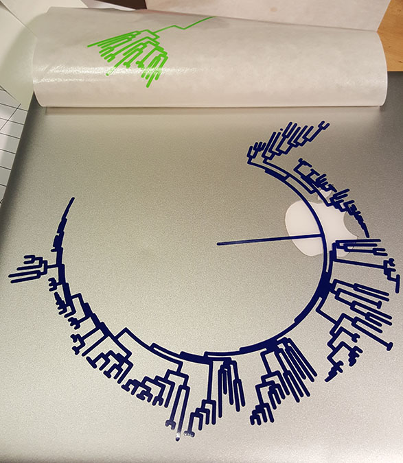
I repeated this process for the eukaryotes, and I was quite thrilled with the result! The alignment marks worked great, aligned the different layers within a fraction of a millimeter.
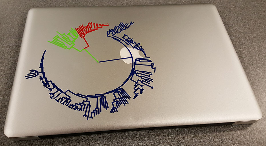
A comment on the content, distance along paths is proportional to the amount of evolutionary divergence. The little red dot is just above us humans, and the little blue dot is just above one of my favorite bacterial species, Mycoplasma mycoides. I was happy that we happened to be rendered close to one another, even though we are far apart evolutionarily. I was quite stunned by the diversity of bacteria. Plants are just a few lines over from us, so certain bacterial species are FAR less related to one another than we are to plants.
Towards my final project goal of building a microscope, I decided to prototype an inert motion axis using press-fit cardboard. In particular, I was interested to make a motion axis that locks into place and can be translated increments less than the lattice spacing between parts. I had a look at the thesis Neil linked about motion stages, which were composed of rigid vs flexural units. I thought I could make a flexural part and a rigid part, similar in spirit to ongoing research efforts in the CBA. In particular, I was interested in extension along an axis but rigid otherwise, so then I can couple the axes together to make more complex motion systems. For example, we could imagine mounting optics and then translating them by small amounts.
I was using the Trotec laser, so I first tested a range of cutting conditions, trying to find maximal speeds and minimal powers to cut the material. All were with air assist on and automatic Hz.
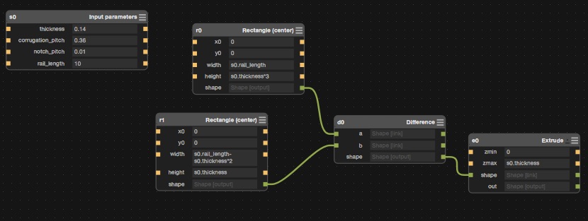
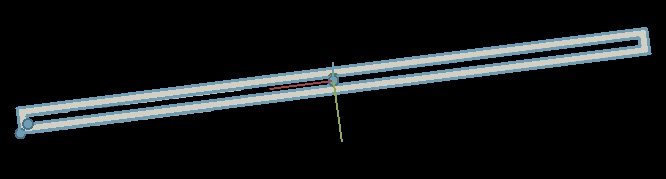
For parametric design, I started to use Antimony version 0.9.2 by Matt Keeter, downloaded the dmg from Github. For example, here is a rail
Then I had a look at some living hinge designs, such as by Anders Haldin. I gave something similar a shot, which worked quite well for bending out of plane, but performed poorly in compression or tension. I next tried to minimize the amount of material, to put less material near the joints. This was a bit softer in compression or tension, but there was strong hysteresis and permanent deformation of the material, and there was a strong tendency to buckle out of plane, which I did not want. I tried both parallel and perpendicular to the corrugation, and neither softened the spring constant.
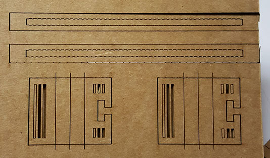
So then I actually took a look at the material and thought about the constraints, and I realized the contacts between the corrugation and the sides will suppress extension or compression! But the corrugation itself represents stored path length! So the cardboard can have a natural tendency to extend in one direction, perpendicular to the corrugation, if only we cut the sides between ridges. This worked quite well! Each cut enables local expansion by about 50%. One important detail was I used different colors, so I could flip the cardboard and co-register the back cuts to the front cuts. Since the cut through settings were enough to pierce to the other side but left tiny sparse tabs so you pop out the cardboard, then I could align the back cuts to the front cuts.
Front view
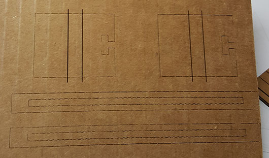
Back view
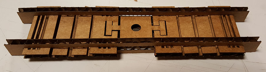
Next, I wanted to create some resistance, so after displacing the central part, it stays more or less in one place, something like a lock on a micrometer screw. Therefore, I used the cut through first layer settings to create little spring-loaded tabs, and I cut little ridges in the side rails that matched the tabs. Also I made a puzzle piece mechanism to attach the central unit to the two spring units on the sides, we could imagine having different optics in there and swapping them out.
Since there are two springs competing against one another, I thought this might be interesting in terms of revealing where non-linearities arise in the springs.
Top view
Side view
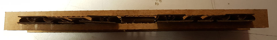
It worked somewhat well! I think this design is limited. Due to the large pitch of the corrugation, displacements along the length are limited. I will next try to cut rail slides in the cardboard, so the pieces slide along the rails. I will undersize the grooves a bit, so compression of the rail by the groove provides a local anchoring force.