For my confocal scanner final project, I learned to use EAGLE to design a synchronous detection board. In addition to the EAGLE manual and tutorial, I found the tutorials on SparkFun were quite useful.
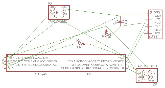
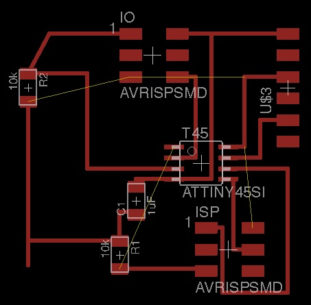
In particular, I started with Neil's synchronous detection board, but I replaced the phototransistor and LED with a 2x3 pin header to make breakout boards, and I also removed the current limiting SMD resistor in series with the LED so that I can swap out different resistors to change the current through the laser diode. For earlier versions of the board, I used GIMP to manually make changes. But when I added in the 2x3 header, there were so many changes that GIMP was no longer practical, so I used EAGLE and started from scratch with a new schematic.
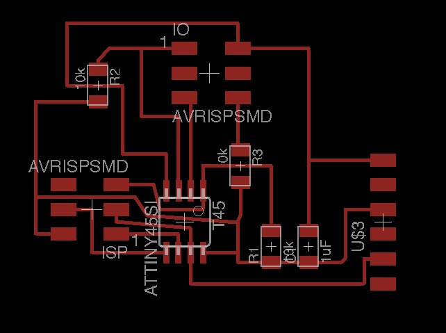
I first attempted to route the wires manually, but I had trouble finding how to connect the wires. In my first attempt, I would have needed a lot of 0 Ohm resistors to jump traces.
Then I tried the autorouter. This worked quite well, but I was concered the traces were too close together. For example, there were five rows of traces under the microcontroller, and a couple of traces between pads on the microcontroller.
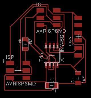
So then I resumed the manual routing, and by looking at Neil's board, I was able to reduce the number of puzzles and finally converged on the version above. It was a bit tricky for me, because I replaced resistors with the header, and in Neil's board some of the resistors are used to bridge over traces. By adding a single 0 Ohm resistor, I was able to finish the design.
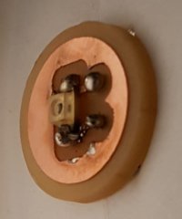
I also made a breakout board for the detector, so I could move the location of the detector and I used female pin headers from the opposite side of the board, so I could run the wires from the other side and I would not have wires in the beam path. That board was so simple that I just drew the pads in GIMP, and I copy/pasted from other pngs for the pads that match the package of the phototransistor, and the spacing and diameter of holes for the female pin headers.
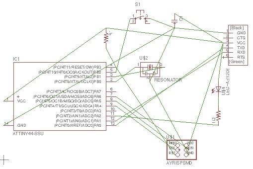
I started to dive into the datasheet. In particular I read about the analog comparator and the 10-bit ADC on the ATtiny45. In this application note I read how quantization by ADCs introduces error, especially near the edges of each step, and 1 LSB (least significant bit) unit is the width of one step. The integral nonlinearity (INL) refers to the maximum distance between the ideal and actual AD conversions. The slowest conversion time is 260 microseconds. The ADC also includes a temperature sensor! Also it can perform in free running (uses the ADC Interrupt Flag as a trigger, kicked off by writing a logical 1 to the ADSC bit in the ADCSRA) or single conversion mode. Also the differential inputs have programmable 20x gain.
Many future directions. On my mind at the moment, I would like to learn more about the interrupt system.