WEEK 10: _ add an output device to a microcontroller board design and program it to do something.
Understanding Charlieplexing
Charlieplexing is an amazing way to make the most of pins on you ATTiny. If fact, with Charliplexing you can output to a total of:
N * (N-1) LEDs, for N pins
I chose 4 pins to 12 LEDs, but this can easily be 6 to 30 LEDs or even 10 to 90 LEDs! (Just more soldering)
My first task was to understand the way in which a Charlieplexed array is wired. LEDs are a good place to start, but eventually I hope to multiplex heating elements for my final project. Here is a explaination Charlieplexing (click picture to enlarge), the big bro of Multiplexing. Also, for visual pattern learners like me, I made this diagram which I think best explains the wiring:
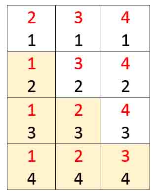

Hmmm... How would this work for an RBG LED? would we need more trace layers?
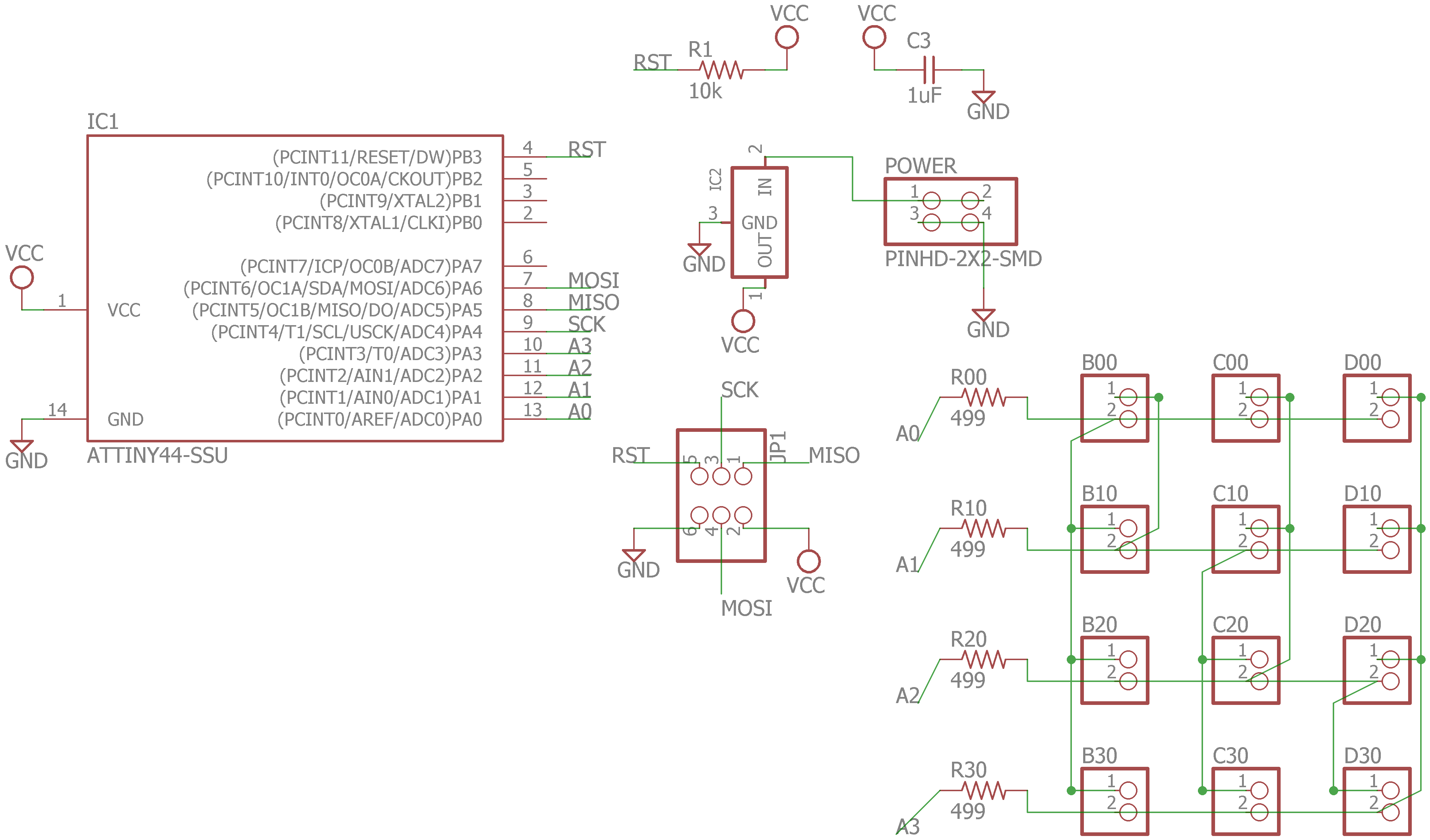
Output Board Design
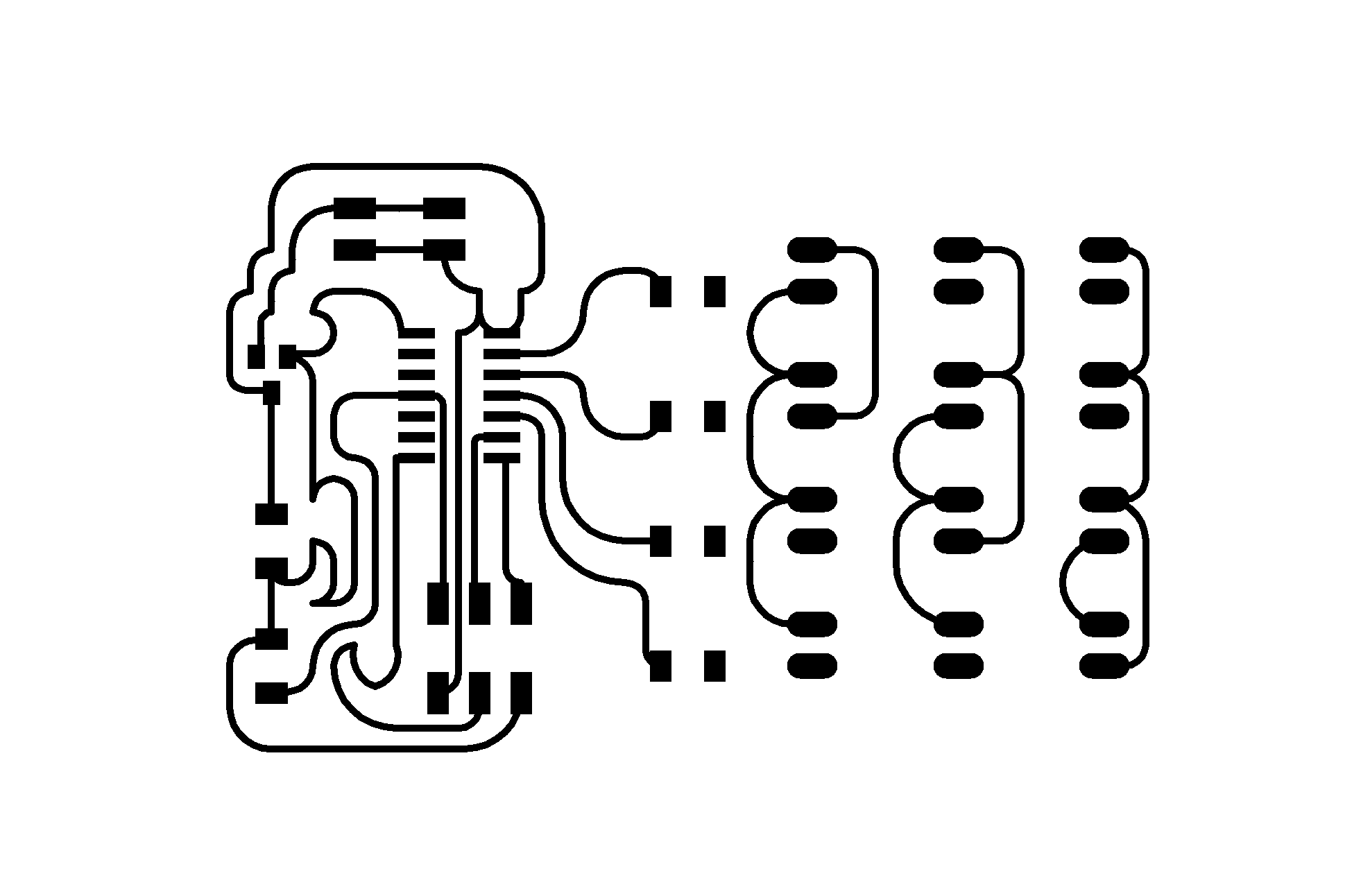
I created a board identical to the one Neil provides in his example, here. Understanding the wiring is key becuse in the static board schematic Neil has, it is near impossible to see where wires are running, when overlapped by other wires on a square grid. That's where understanding the pattern comes in!
I designed 2x1 pin headers on my arrays as opposed to LED trace pads, so there is flexibility in what goes on the ends.
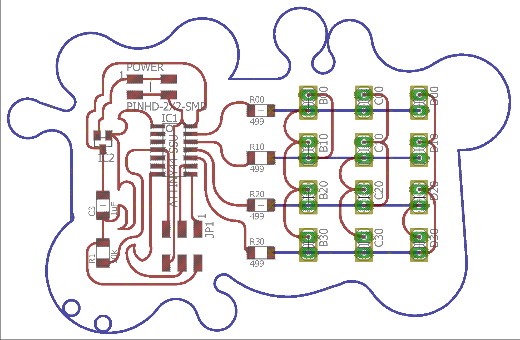
Output Board Fabrication
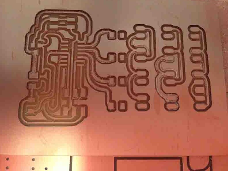
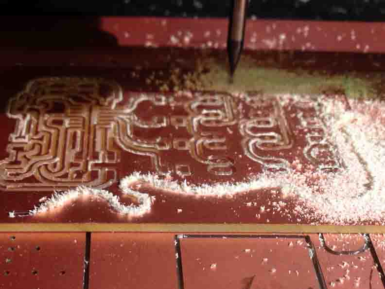
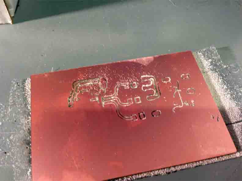
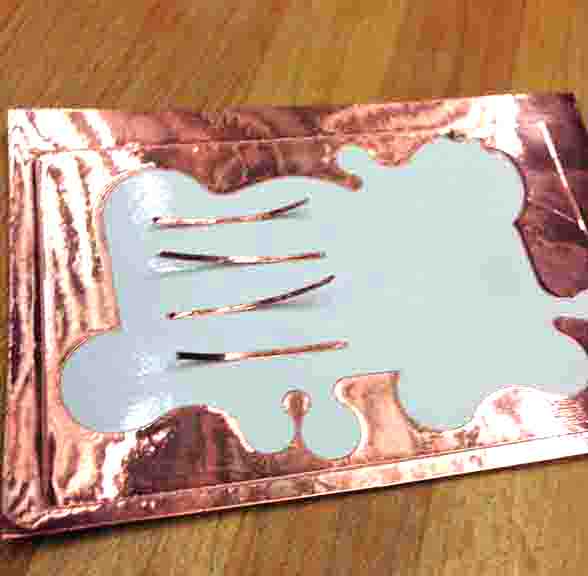
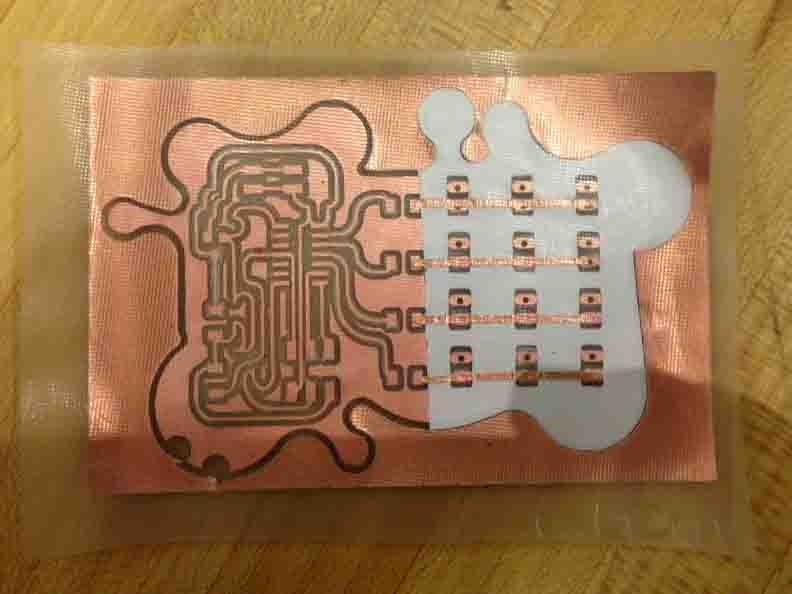
Here are all the traces, as follows: (1) Board Cut, Modella at 1/32; (2) Trace cut, Modella at 1/64"; (3) White vinyl overlay, Roland; (4) Copper over-over lay, Roland. The curvy board design makes a very good guide for alignment!


And of course, there is some good milling and some bad milling to be had. Lesson: before there was anything, there was really well placed double stick tape.
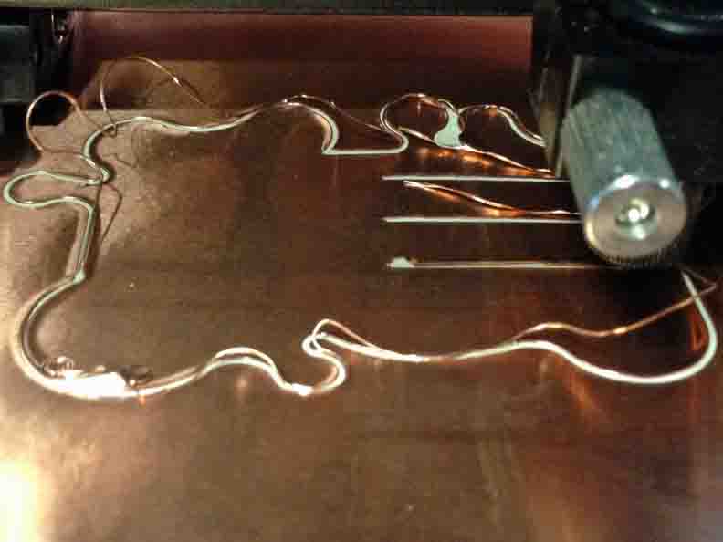
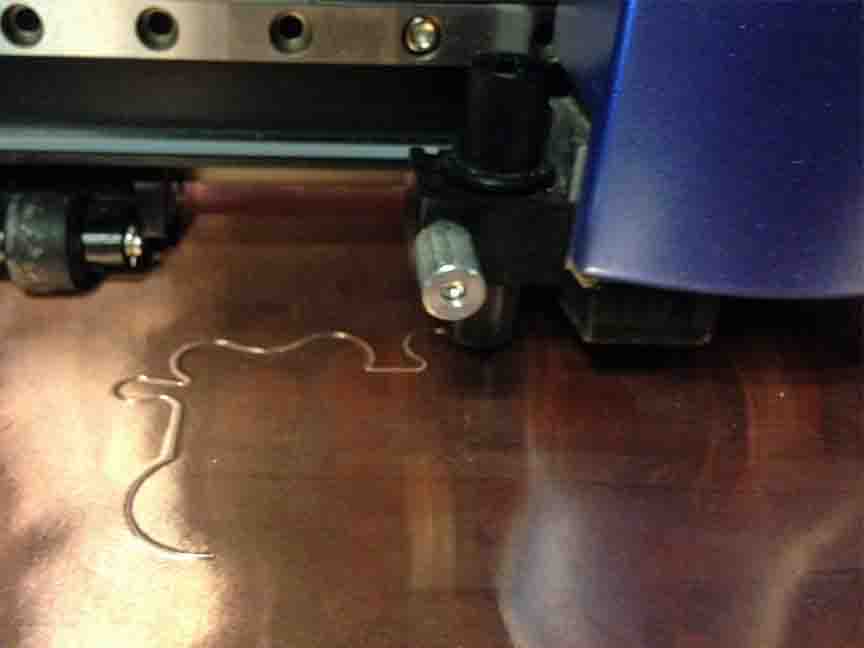
And vinyl cutting copper traces proves to be non-trivial as well. A warning to future copper trace cutters: even with the lightest knife pressure, copper has a tendency to curl up off it's backing when cut at a 16 mil or even 50 mil width. It is a fault of the not-so-adhesive backing, which also makes weeding difficult. I suggest VERY thick traces what using copper vinyl cuttings (i.e. 100 mil, even!) That aside, I have a fairly simple route so it got to the right place on my board anyways.
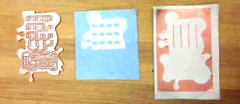
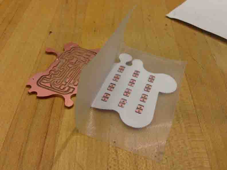
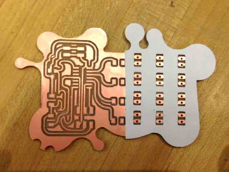
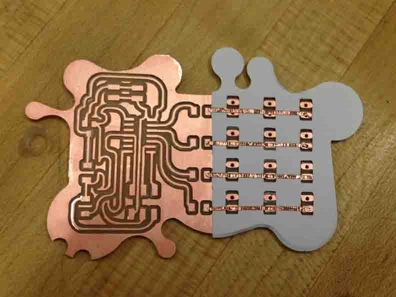
So, after milling and cutting you should be left with three ingredients, a PCB board, an insulative piece of vinyl and a conductive piece of 'vinyl'. The were adhered in the order of the following pictures.
Programming an Output Board
The two files can be found on the HTMAA website. I altered the file slightly to remove one row and column of LEDs. Find the links here, and save these files to a folder to be referred to from your terminal:
_ > hello.array.44.c
_ > hello.array.44.make
I only soldered the first row of LEDs before testing, as a check on the board's wellbeing before attaching all of the rest of the hardware.
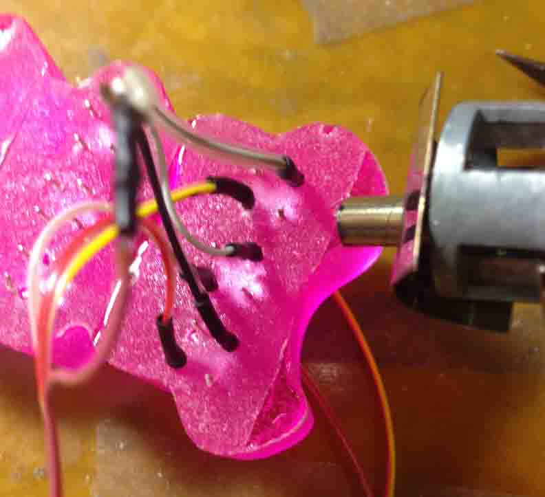
Now for programming in C. It only takes two lines in bash with the files above.
OUTPUT:
OUTPUT:

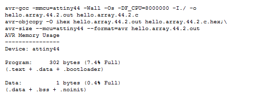
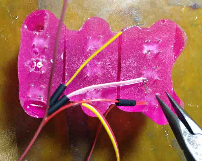
Excellent! Since the green board-mounted LED row is working, I am confident to go ahead and solder the rest. This is fairly manually tedious, but the end product turns out pretty neat by keeping wires short and using heat shrink insulation on the stripped wire sections. Voila!
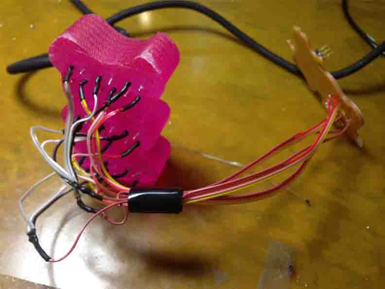
FLASHY BEAR.