09 Nov 2016 · 2 min read
The assignment for this week was to design a microcontroller that measures
something in the physical world.
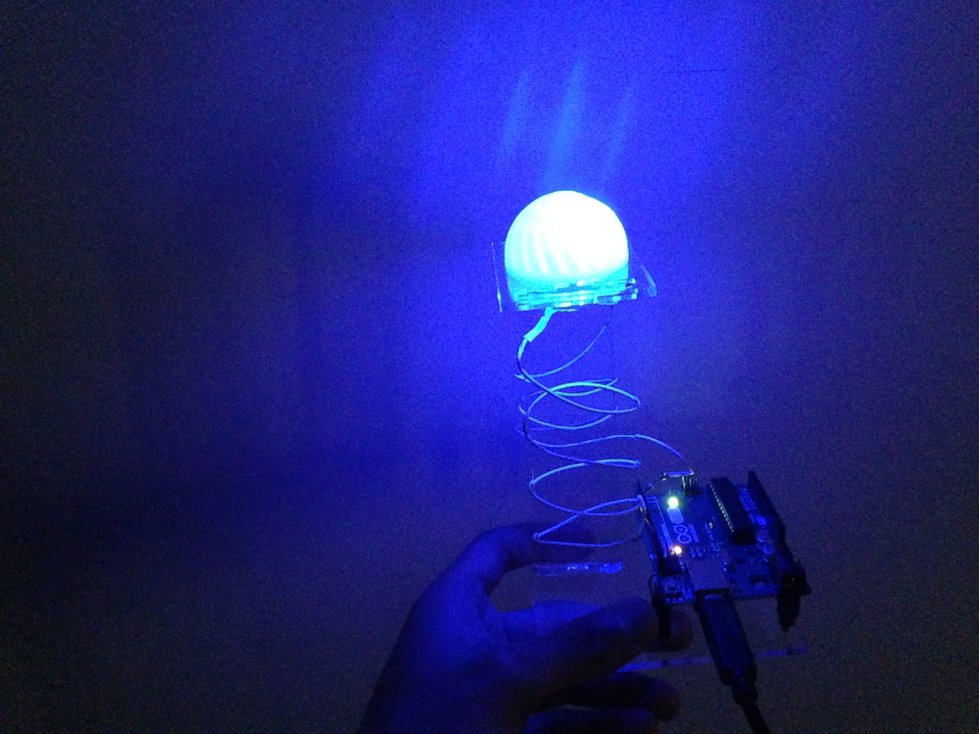
I decided to make a microcontroller that measures ambient light. I have a small
nightlight in my room that I built a couple months ago, and I thought it would
be cool to modify it so that it automatically turns on when it’s dark. Here’s
my nightlight:
I didn’t actually modify my nightlight for this week’s assignment, but I did
get some practice working with phototransistors.
Design
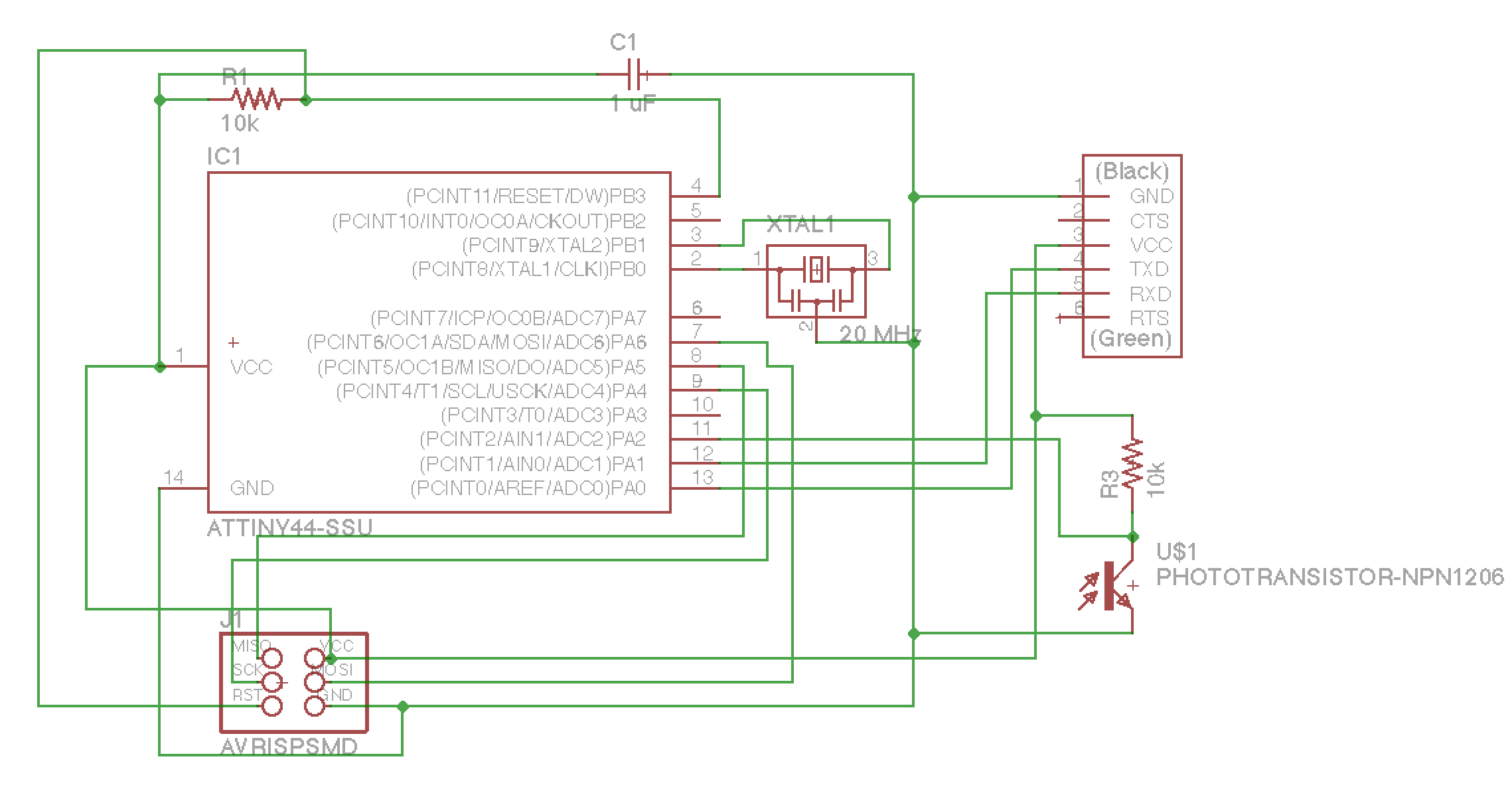
Using the skills I learned a couple weeks ago, I designed a schematic for an
ATtiny44 with a visible light
phototransistor:
After designing the schematic, I placed parts on a board and let the autorouter
do its job:
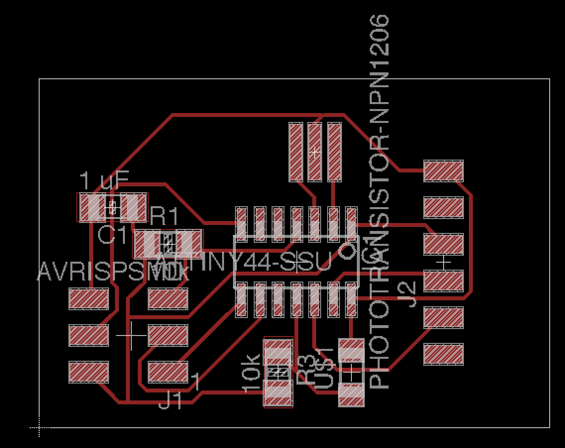
I made sure to leave enough space in front of the FTDI connector so that the
SMT component would be supported. This is something that I didn’t do last time
I designed a board with an FTDI connector, and then I had to be super careful
about not putting any load on the connector to avoid breaking the board.
I exported the board design and created traces and an outline to mill.
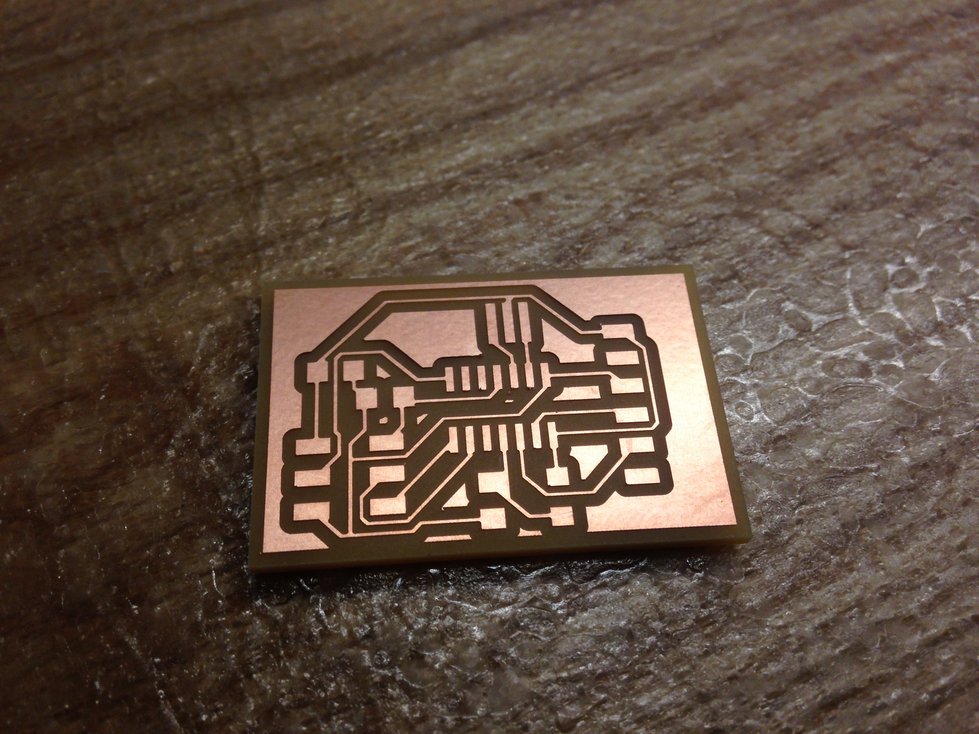
Production
Producing the PCB was pretty straightforward. Here’s the milled PCB:
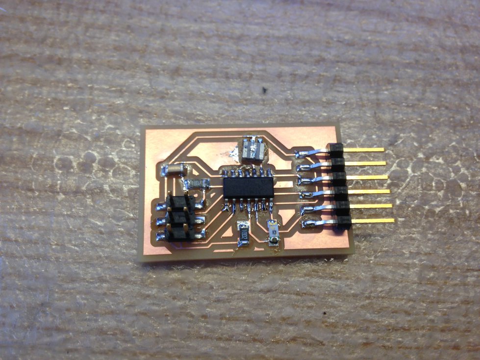
And here’s the finished PCB with all the components:
Programming
I adapted code from
here for the
ATtiny44. Here’s my Makefile and
light.c.
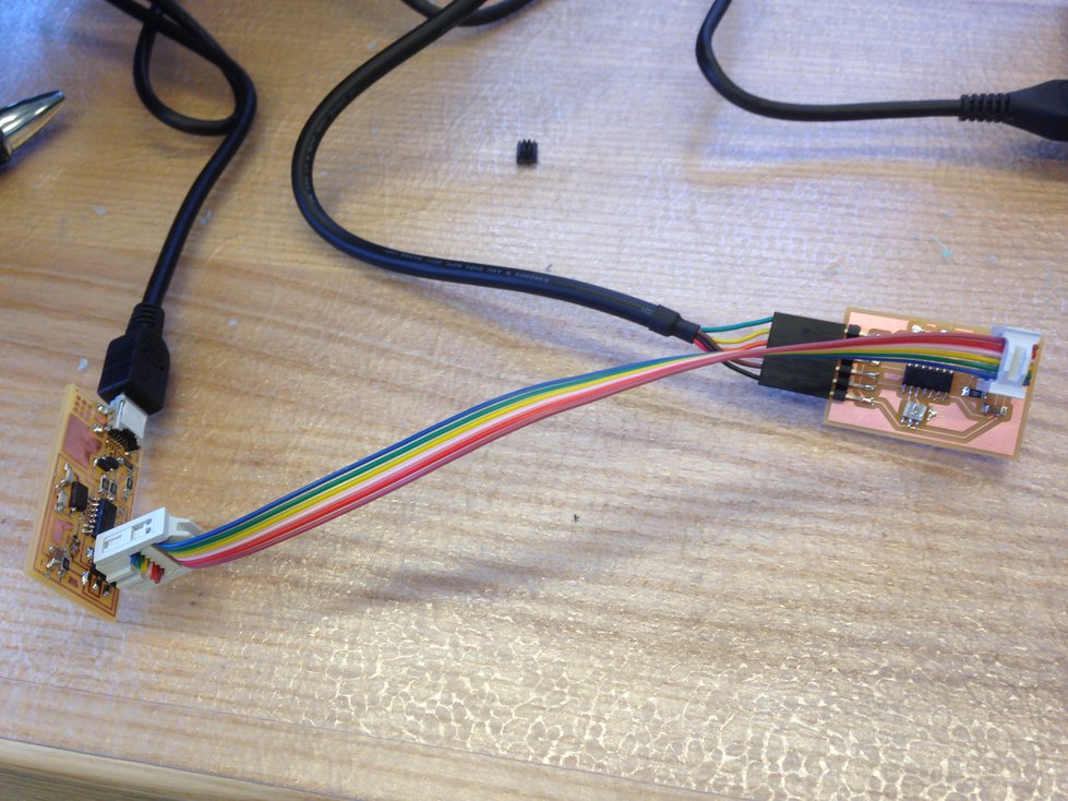
I programmed the board using my FabISP:
Result
Running the light.py script on my
computer, I could verify that the board worked as expected:

02 Nov 2016 · 4 min read
The assignment for this week was to design a 3D mold, machine it, and cast
parts from it.
Because this was my first time molding and casting, I decided to keep it simple
and do a one part mold. I followed a three step process — I machined a
positive out of machineable wax, made a mold
using OOMOO 25, and cast a part
out of
Hydro-Stone.
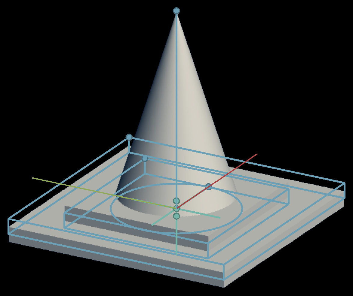
Designing the Part
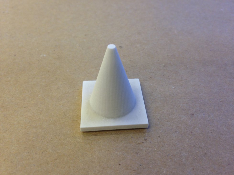
I decided to make a miniature traffic cone. I designed the part using
Antimony, and the process
took about 5 minutes:
Machining the Positive
I used fab modules to drive a Roland SRM-20 to
machine my piece, using a two phase process, first doing a rough cut and then
doing a finish cut. For both phases, I used a 1/8” flat end mill.
Without a good understanding of how the software worked, I accidentally ended
up machining a negative instead of a positive. Here are the results after the
rough cut, which took about five minutes:
With a better understanding of the software, I started another job to machine a
positive. I tried to reuse my material, but the piece didn’t fit, so I
cancelled the job:
I got a fresh piece of machinable wax and started another job:
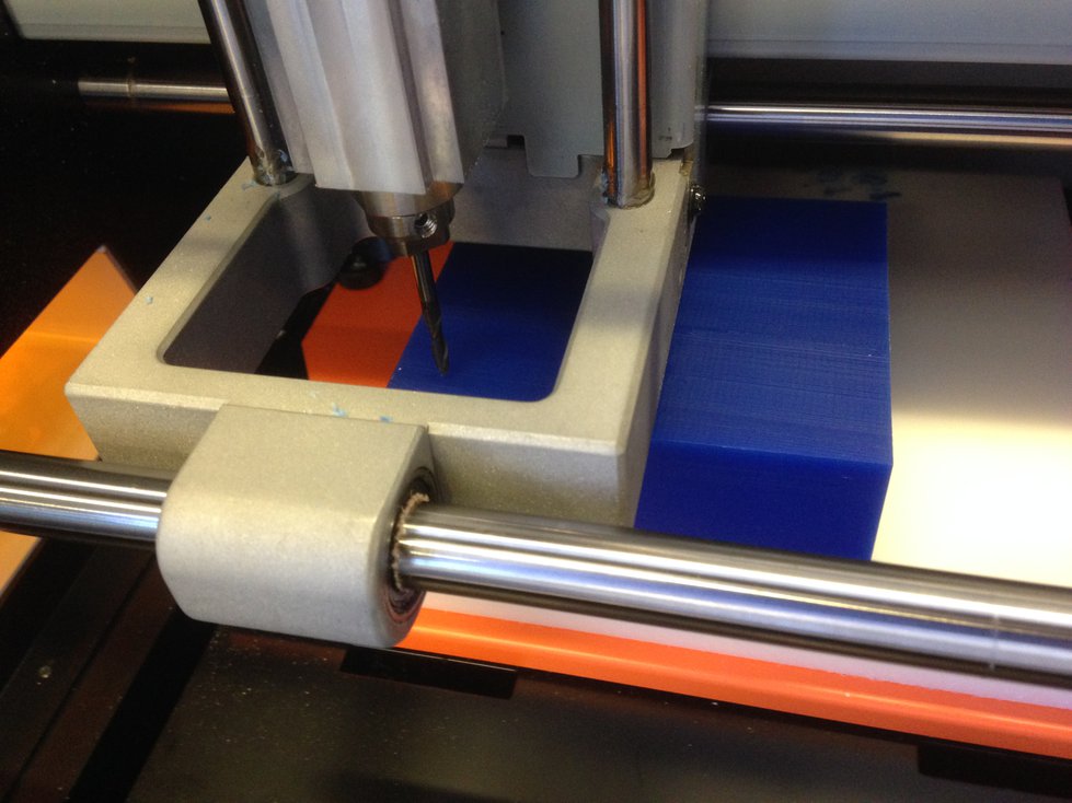
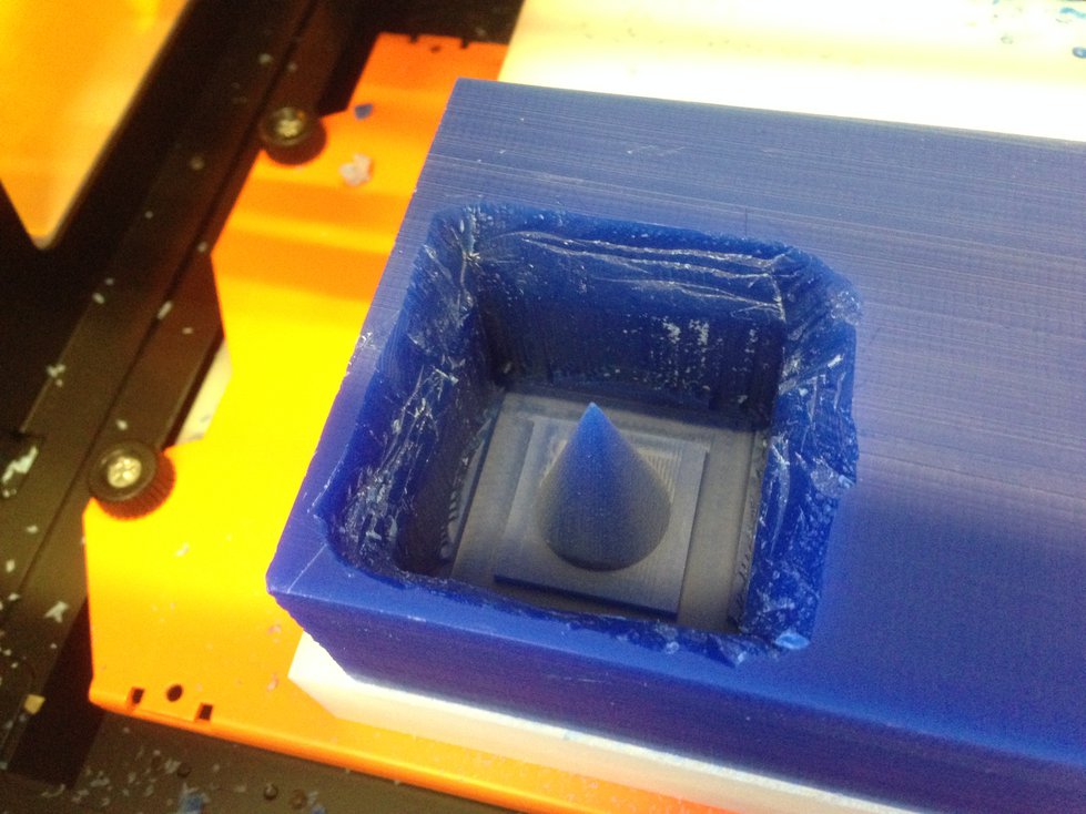
This time, I had another problem. My piece was very deep, and the end mill was
not quite long enough to reach the bottom of the piece without the collet
coming into contact with the surface of the material. It was only a millimeter
or so, but still, it caused problems. It seems that the SRM-20 has some way of
detecting this kind of condition, perhaps reacting to a suddenly increased
torque at the motor. After waiting for about 40 minutes, my job was 98%
complete, and the machine automatically stopped and terminated my job. The
collet came into contact with the material at the top right:
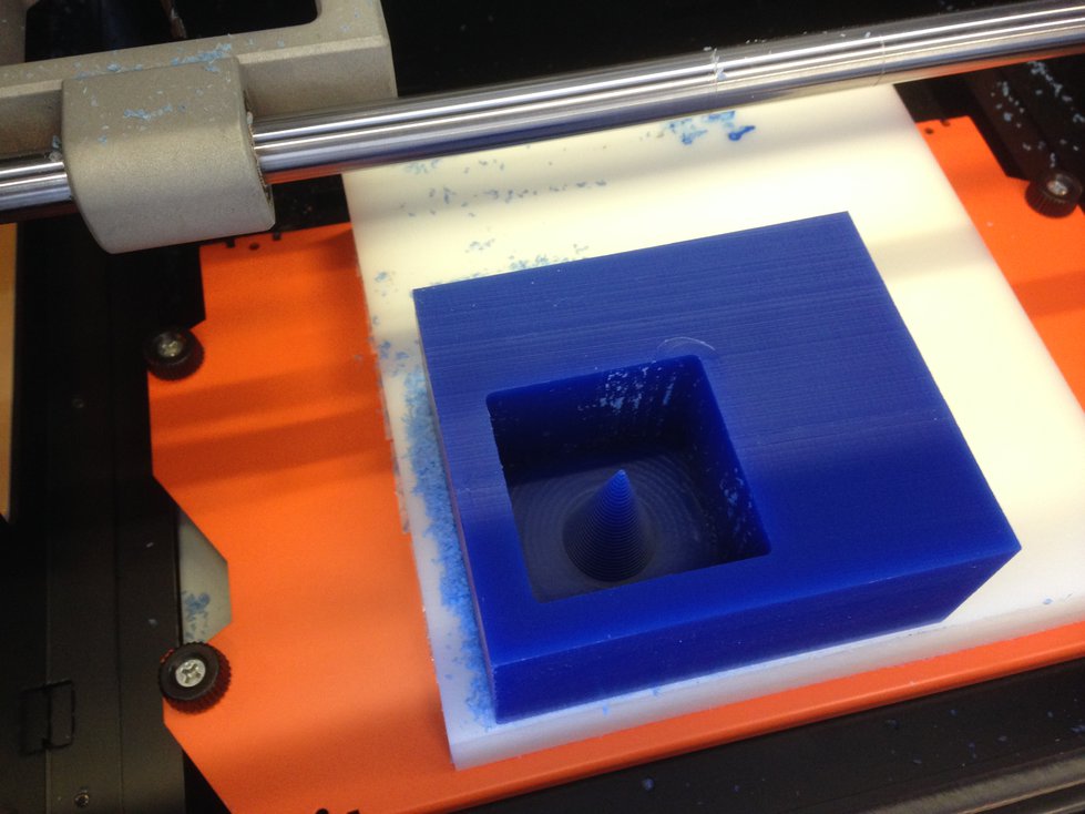
I considered starting another job to mill out material to make space for the
collet. My friend Kevin
Kwok
had an even simpler idea — manually carve out a small amount of material
using a utility knife:
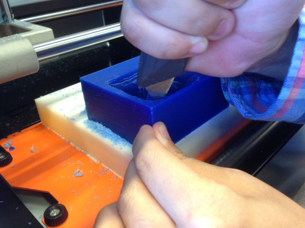
The process took about 5 minutes. Next, I had to deal with another problem: my
job had been terminated 98% of the way through, and I needed to redo the last
2% of the job. I downloaded the G-code for the full job, manually removed the
first 98% of cutting instructions while leaving the configuration code in
place, and sent the modified code to the printer. It worked.
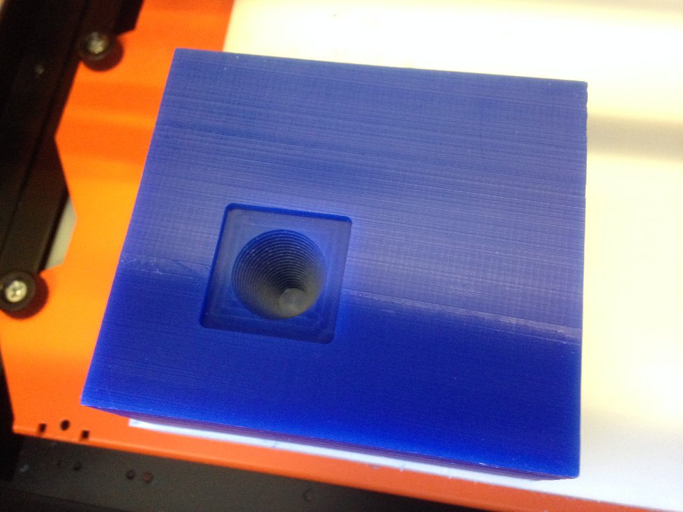
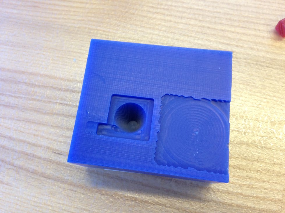
Next, I did a finish cut of the material. This process took about 30 minutes,
and everything went smoothly. The finish quality looked really good:
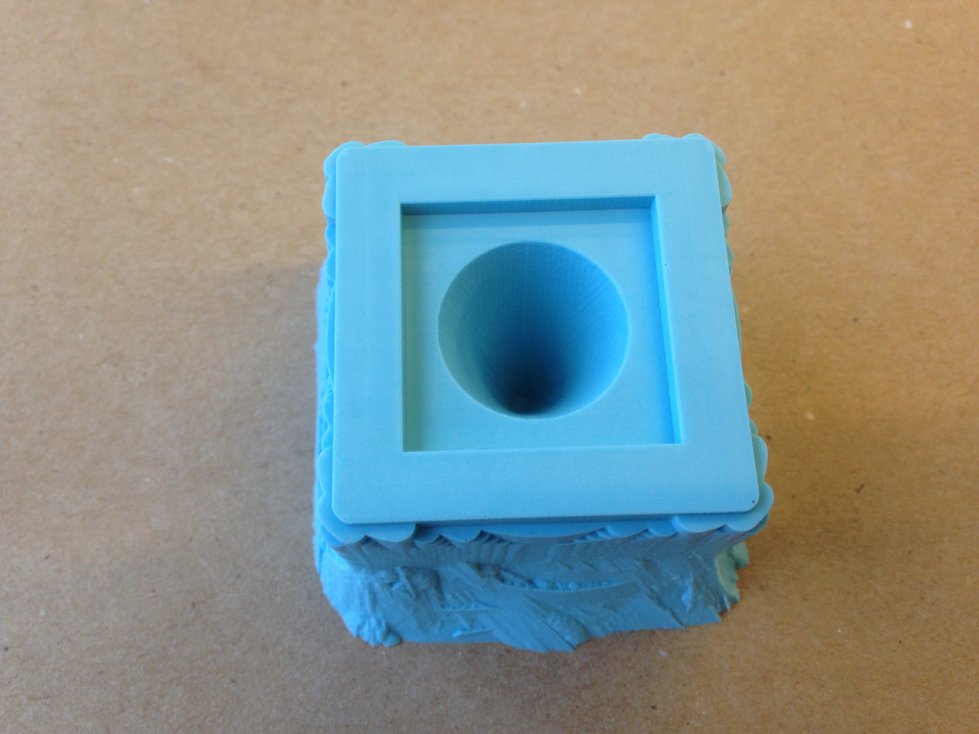
Making the Mold
I made a mold using OOMOO. I mixed the two-part silicone rubber following the
instructions on the packaging and poured it into my milled wax. Afterwards, I
spent 5 minutes trying to release air bubbles by manually tapping the piece:
After letting the OOMOO set overnight, I released the newly created mold from
the machinable wax:
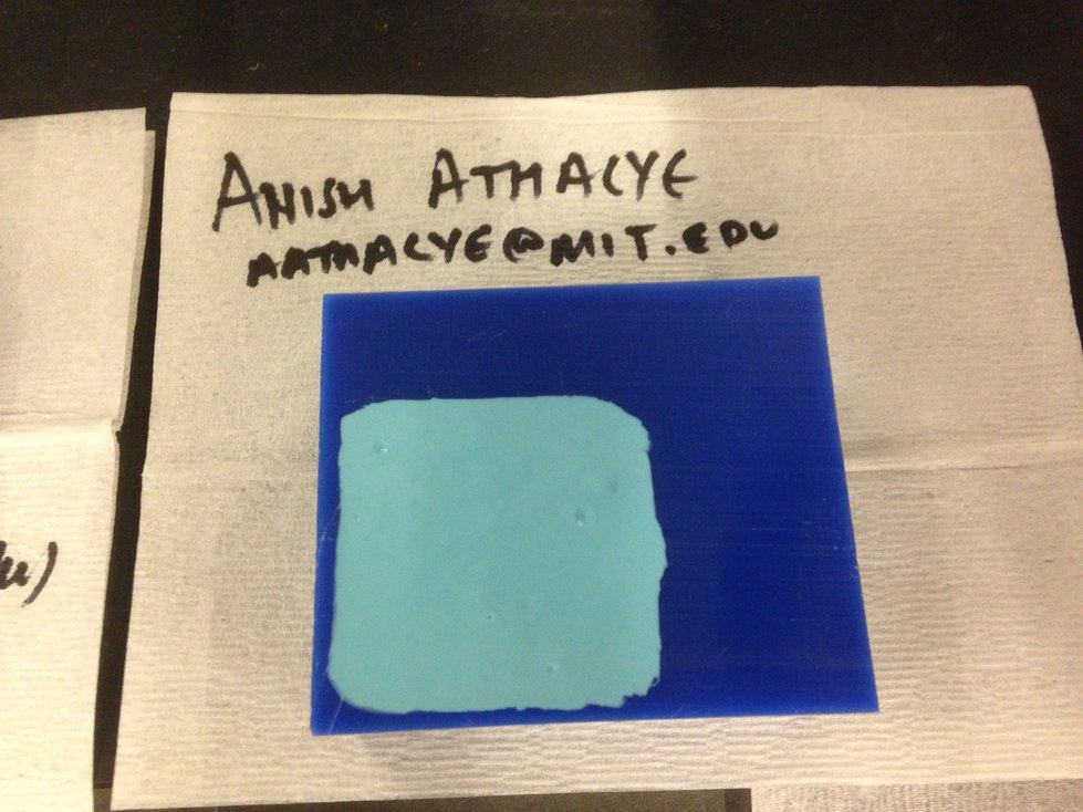
Casting Parts
I cast a part out of Hydro-Stone. I followed the instructions on the packaging
to mix the powder with the appropriate amount of water, and I poured the liquid
into my mold:
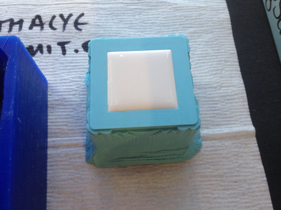
After letting the piece set for an hour and a half, I removed it from the mold.
Here’s the final result:
26 Oct 2016 · 3 min read
This week’s assignment was to program our hello world board from two weeks
ago.
I’ve had a good amount of experience with embedded program, so I was pretty
comfortable with this week’s material.
Following the instructions from
here,
I downloaded the starter
code
and
Makefile.
I used my own FabISP from a previous assignment.
Serial Echo
To program my board, I ran:
make -f hello.ftdi.44.echo.c.make
sudo make -f hello.ftdi.44.echo.c.make program-usbtiny-fuses # only necessary the first time
sudo make -f hello.ftdi.44.echo.c.make program-usbtiny
The first time I tried, it didn’t work properly. After debugging for a couple
minutes, I realized that my cable was connected backwards. After correcting
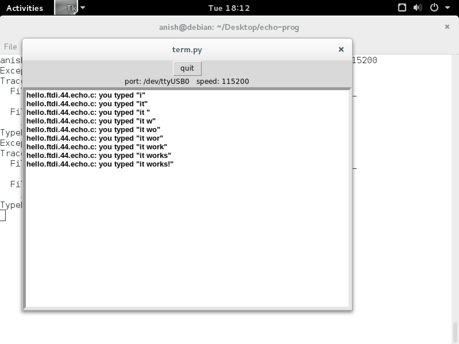
that issue, everything worked flawlessly. The sample program listened via USB
serial and echoed characters back to the programmer. Here’s the program in
action:
Blinking LED
After that, I decided to program the classic “hello world” program for embedded
devices! I made my first blinking light program for the ATtiny44.
// blinking LED
//
// set lfuse to 0x5E for 20 MHz xtal
//
// Anish Athalye

#include <avr/io.h>
#include <util/delay.h>

int main(void)
{
    // set clock divider to /1
    CLKPR = (1 << CLKPCE);
    CLKPR = (0 << CLKPS3) | (0 << CLKPS2) | (0 << CLKPS1) | (0 << CLKPS0);

    // http://maxembedded.com/2011/06/port-operations-in-avr/
    // our LED is connected to PA3
    DDRA |= (1 << PA3); // set PA3 to output port
    while (1)
    {
        PORTA ^= (1 << PA3); // toggle LED
        _delay_ms(1000); // wait for a second
    }
}
Controllable LED
As my final test, I wrote a program that involves both the switch and the LED
on the board. My program read input via the switch, and every time the switch
was pressed, it toggled the LED. I made sure to include a bit of code for
switch debouncing.
// toggle LED by pressing switch
//
// set lfuse to 0x5E for 20 MHz xtal
//
// Anish Athalye

#include <avr/io.h>
#include <util/delay.h>

int main(void)
{
    // set clock divider to /1
    CLKPR = (1 << CLKPCE);
    CLKPR = (0 << CLKPS3) | (0 << CLKPS2) | (0 << CLKPS1) | (0 << CLKPS0);

    // http://maxembedded.com/2011/06/port-operations-in-avr/
    // our LED is connected to PA3
    DDRA |= (1 << PA3); // set PA3 to output port
    // our switch is connected to PA2
    DDRA &= ~ (1 << PA2); // set PA2 to input port
    while (1)
    {
        if (PINA & (1 << PA2))
        {
            // toggle LED
            PORTA ^= (1 << PA3);
            while (PINA & (1 << PA2)); // wait
            // wait a little bit longer as a debouncing measure
            _delay_ms(10);
        }
    }
}
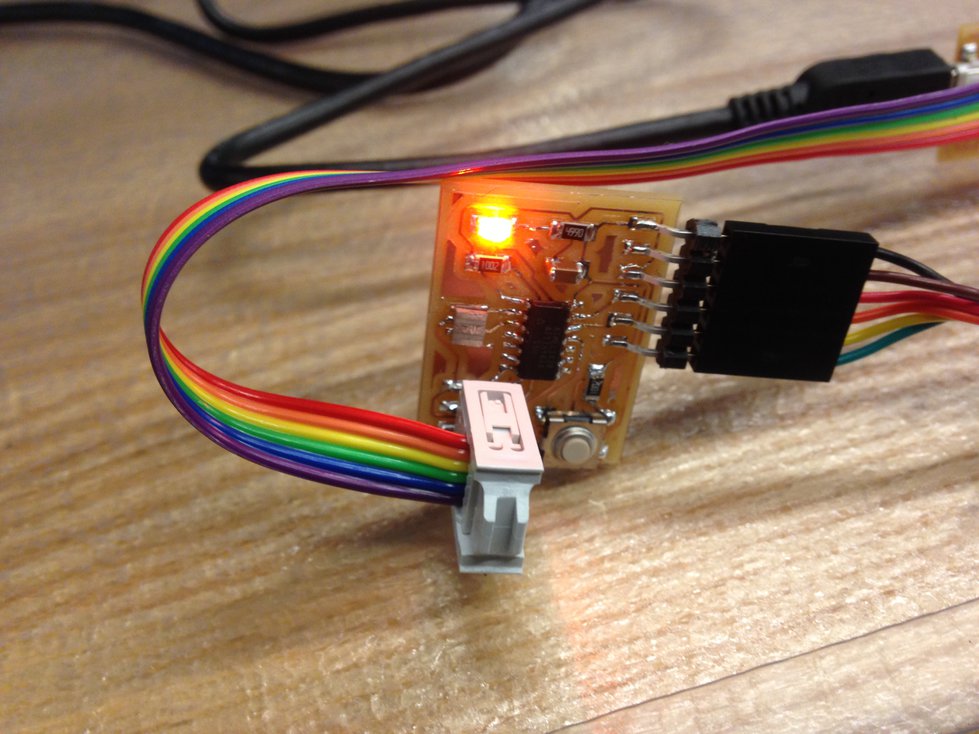
Here’s the program in action. Well, it’s a picture, so it’s not really “in
action”, but close enough: