28 Sep 2016 · 2 min read
This week, I made a
FabISP,
an in-system programmer for AVR microcontrollers.
Milling the PCB
I milled a PCB (using these
traces
and
outline).
I used fab modules to calculate toolpaths for the
Roland SRM-20 milling machine, using all the default settings. I used a 1/64
end mill for cutting PCB traces and a 1/32 end mill for cutting the outline:

After working through it carefully, everything worked on the first try, and I
ended up with a nice finished PCB with pretty clean traces:

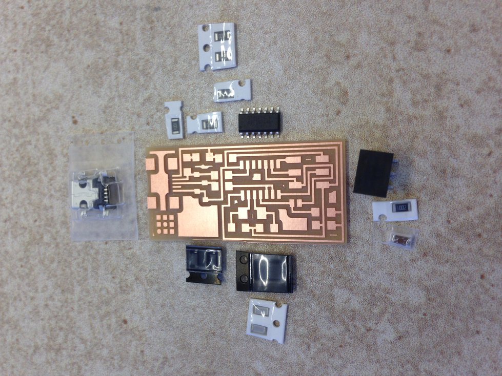
Soldering Components
Next, I soldered the
components. Before starting, I picked out all the parts and made sure I knew what was going where:
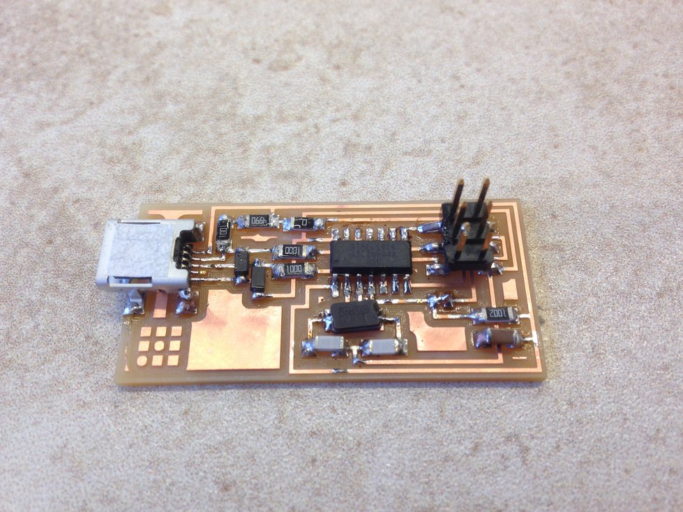
As I soldered components, I tested for continuity to reduce the amount of time
I would have to spend debugging later. After about half an hour of soldering, I
had a board that was ready to be programmed:
Programming
I used Debian 8 (Jessie) and followed the
instructions
for using Ubuntu (Ubuntu is based on Debian). I needed to use sudo when
running some of the commands that talked to USB devices, but besides that, the
instructions worked perfectly.
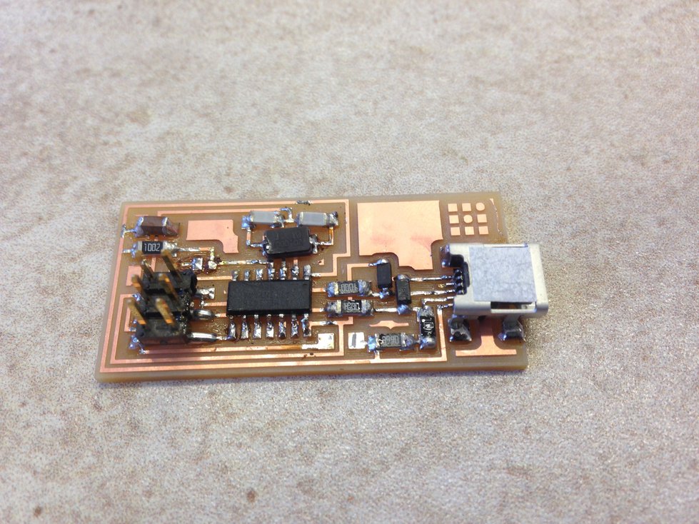
After programming, I removed the zero-ohm resistor and solder joint to finish
my programmer:
21 Sep 2016 · 3 min read
I used the laser cutter to build a press fit construction kit.
I’ve only used a laser cutter once before, and I didn’t really know what I was
doing back then, so in my design, I ended up with loose joints because I didn’t
understand what a laser kerf was. Back then, I compensated with epoxy glue, so
I didn’t end up with a nice friction fit design. This time, I wanted to make
sure I got it right, using a parametric modeling tool and making sure it was
really easy to tune the parameters until everything fit perfectly.
Design
I took the “press fit construction kit” part literally — I designed a part
that was designed to fit together with other copies of the same part, forming a
construction kit that could be used to make all sorts of (mostly very boxy)
shapes.
I used Fusion 360 to parametrically model a square shape with 3 cutouts on each
side for slotting into other copies of the same shape. Parameters included
things like piece size, slot spacing, and most importantly, material thickness
and laser kerf width.

Cutting
I was cutting this on a Universal PLS 6.75. When cutting, I had to experiment
with laser settings to get good results. Initially, I was using the materials
database, setting the material to balsa wood (it was actually cardboard),
0.160” thickness, with a +50% modifier for vector cutting.

That didn’t make clean cuts through the material, so I switched over to manual
control. I tried using 70% power, 8% speed, 300 ppi, and setting the thickness
to 0.160”. That worked a little bit better, but it wasn’t quite perfect — I
still didn’t get clean edges on some of the pieces I was printing. I tried
boosting the power to 75%, and I consistently started getting nice pieces.
Experimentation
After getting the laser cutter parameters tuned, I did my first real cut:

After playing around with the physical pieces, I felt that the notches were too
close together, so I tweaked the design and cut some new pieces. I was happy
with the new results, so I cut 60 copies:

The pieces looked quite nice when neatly laid out on the laser cutter bed:

Final Result
After printing, I ended up playing with the pieces for some time, and I ended
up with this art:

Bonus: Laser Cut Laptop Stand
After getting some experience with the laser cutter, I was interested in making
something useful for myself using the tool. I decided to make myself a laptop
stand, designed parametrically in Fusion 360:

14 Sep 2016 · 1 min read
For my final project, I plan to make a large (~2 meter wingspan) RC glider
capable of serving as an FPV / aerial video platform.
I’ve made a quadcopter before, so I have some experience with building RC
vehicles:

Even though I built the quadcopter myself from parts, it wasn’t from scratch. I
used an off-the-shelf injection-molded frame, and I used an off-the-shelf
flight controller that runs open source software.
For the glider, I plan to do much more from scratch. I plan on buying a motor,
servos, a video camera, a radio receiver, and a radio transmitter. I want to
construct the airframe by hand, and I want to design and build my own flight
controller and program it myself. I’m also going to look into designing and
fabricating my own propeller, which I would like to do if possible.