Final Project
(tracking page)
Week 13
Meta-Machine
test
Week 12
Networking
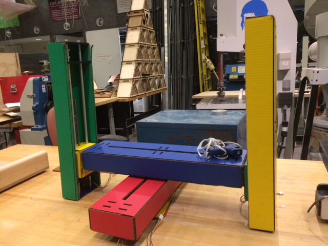
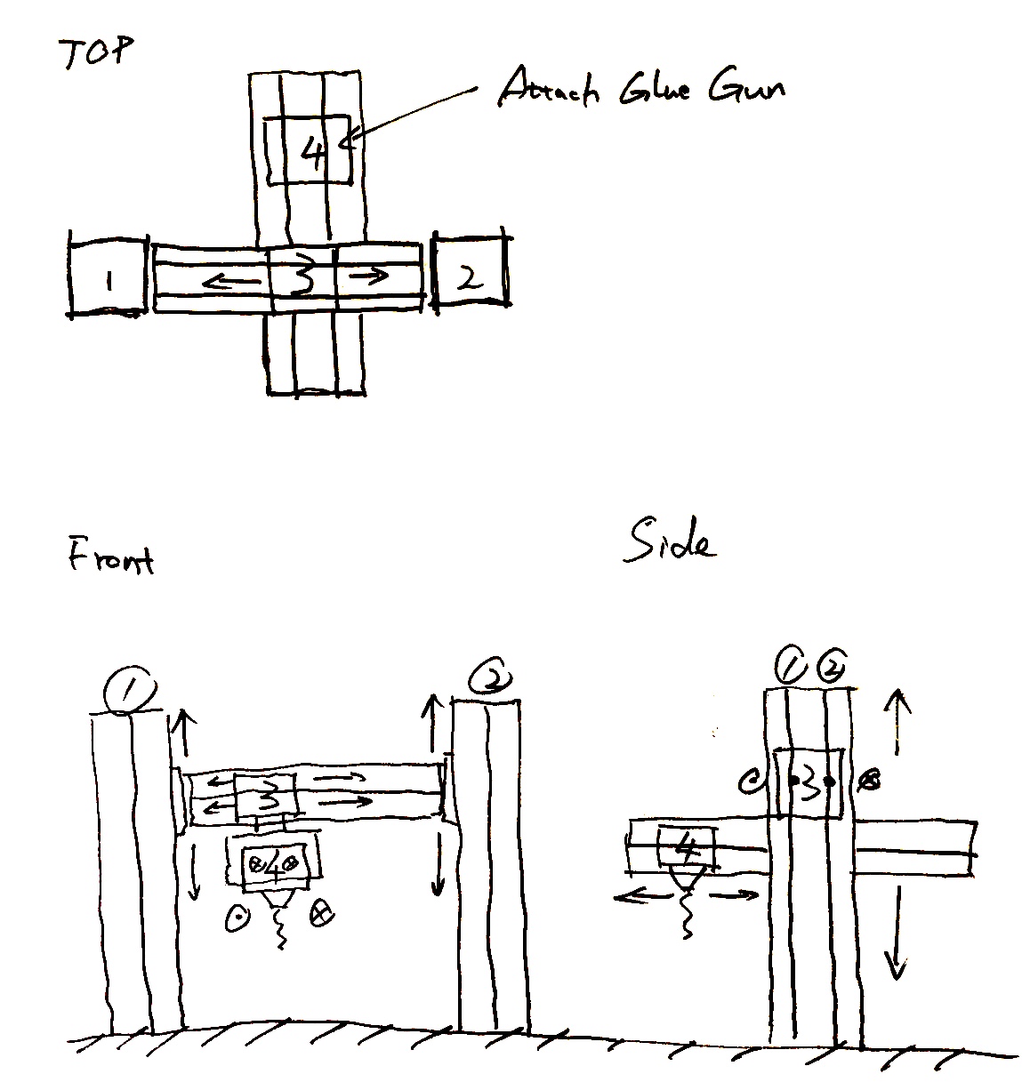
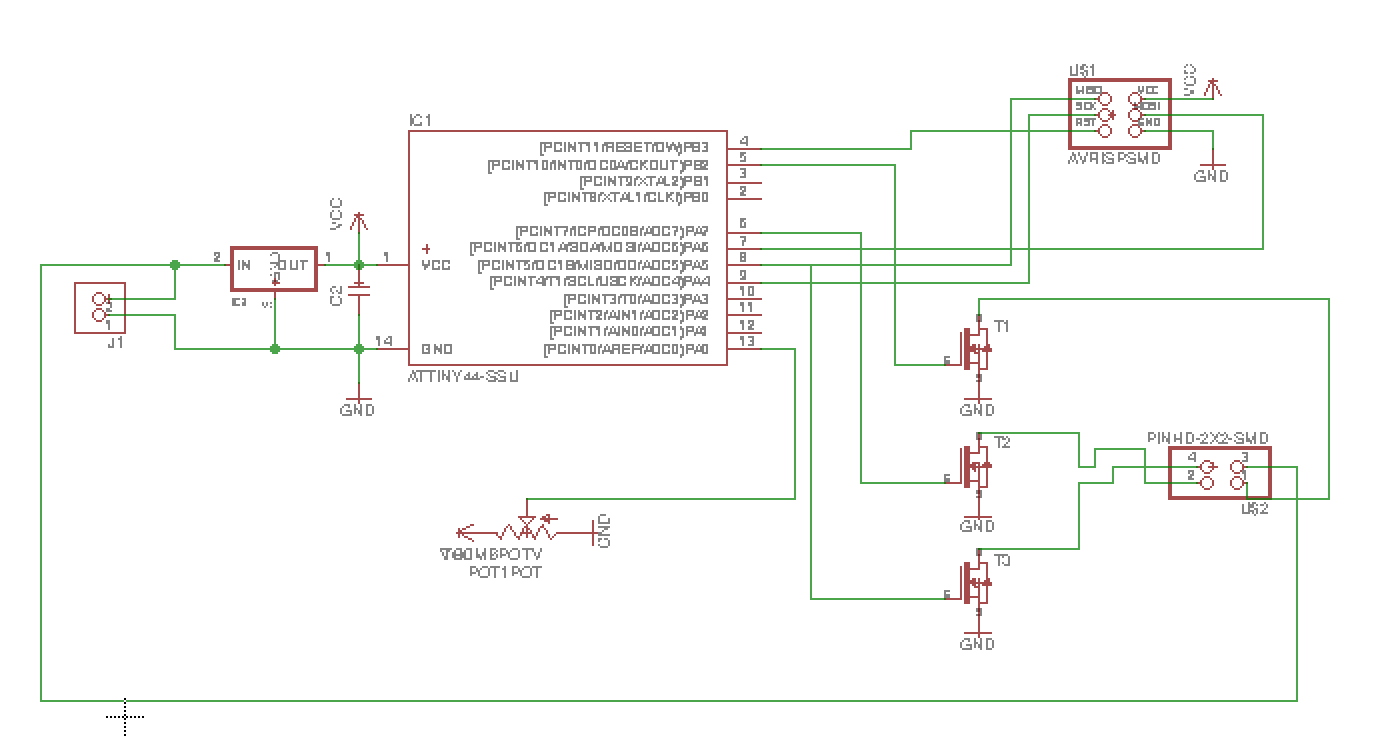
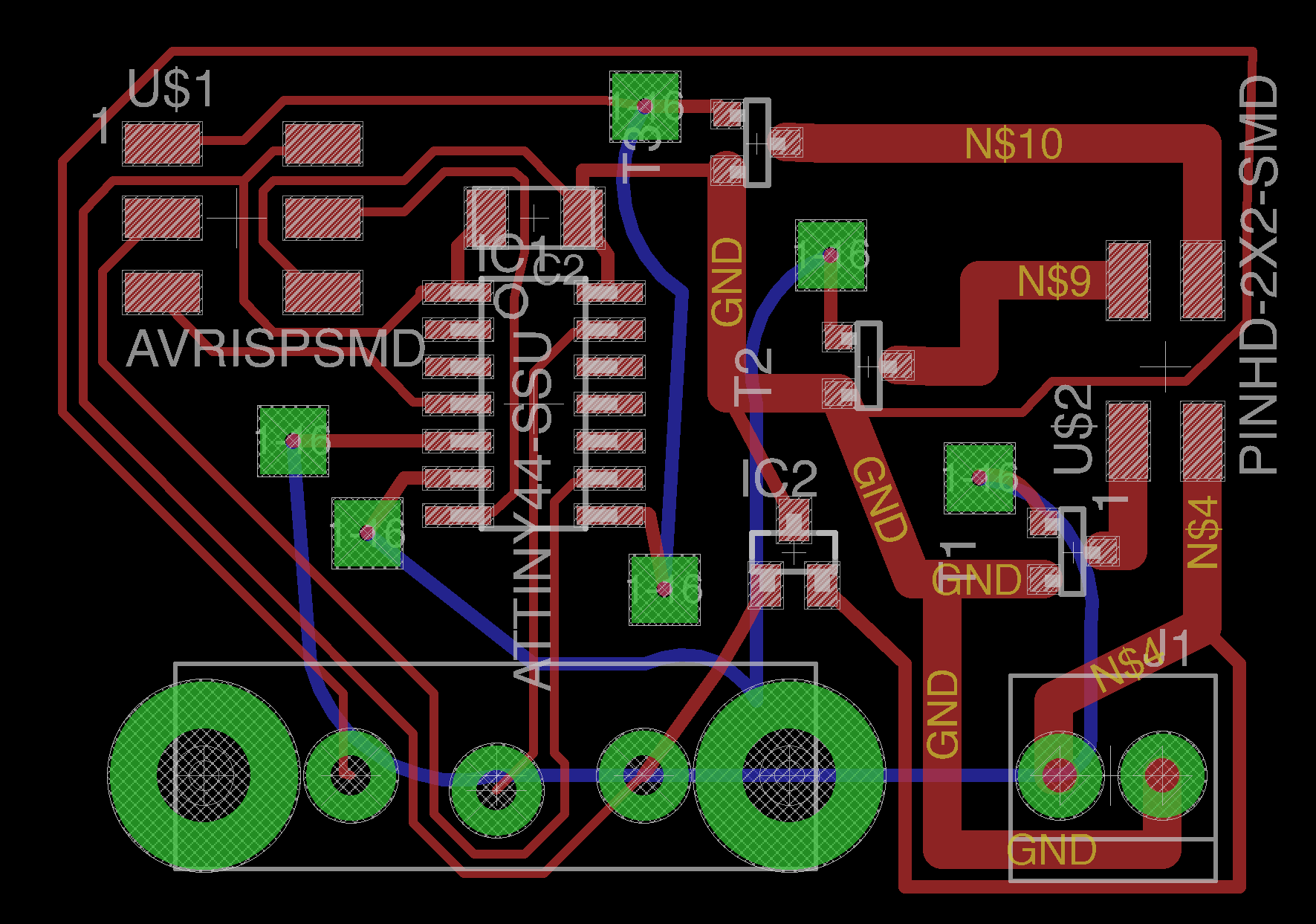
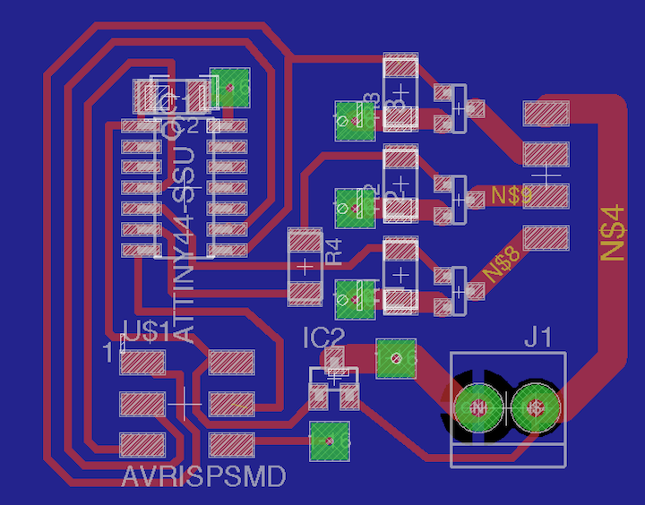
For the final project, I’m making a room-scale crane.
I’m putting networked nodes in 3 corners of the room driving DC motors which control spools of fishing line which will position an end-effector.
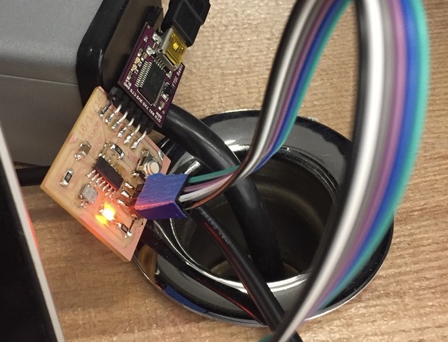
These nodes use the Nordic Semiconductor nRF24L01+ modules to communicate with each other. Modules for the nRF24L01+ half-duplex tranciever chip are sold for less than $1, which means it’s ridiculously cheap.
It operates on 3.3V, so both it and the ATTiny44 are made to be run on regulated 3.3V power.
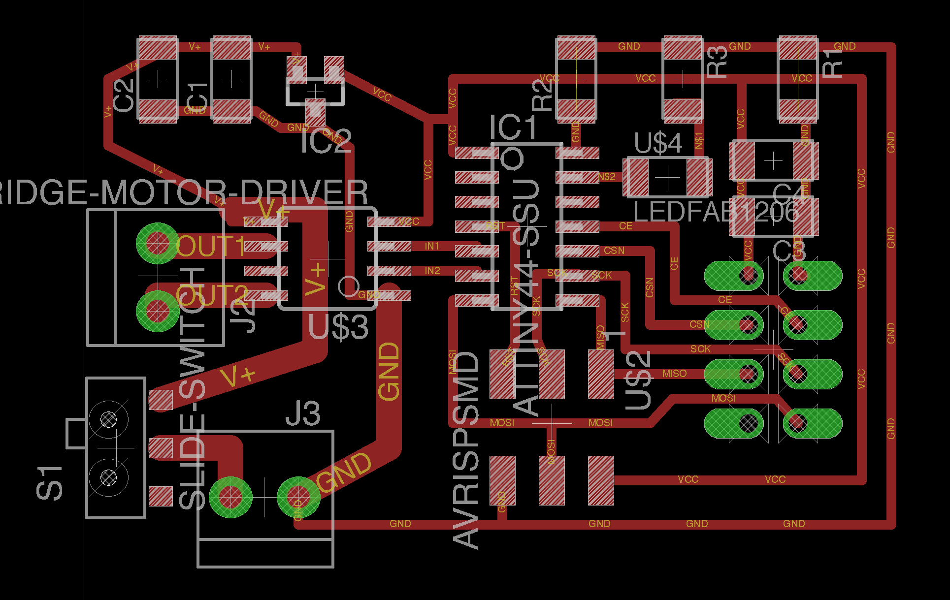
Since it’s meant to drive a motor, I’m using the H-Bridge.
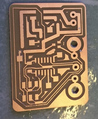
Long story short, I ended up fabricating a bunch of these before finding out that the H-Bridge was being used the wrong way.
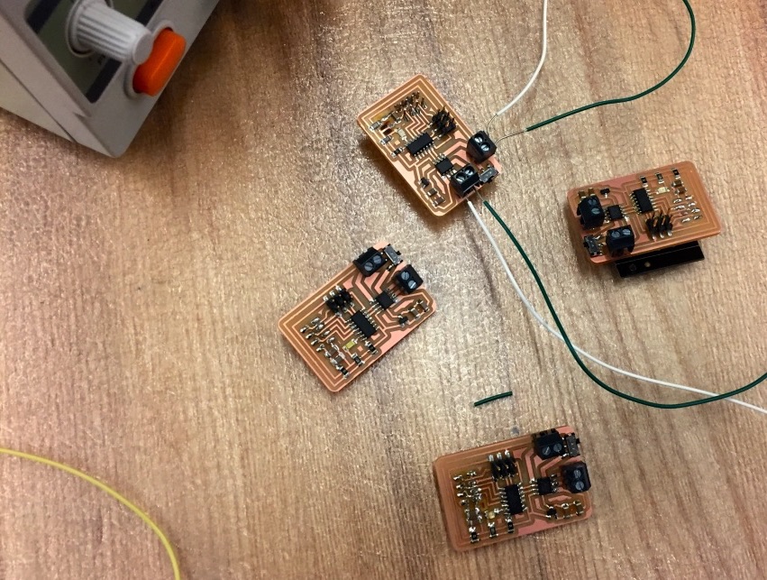
Another rather infuriating bit is that even though all these boards look more or less identical, only one of these four seemed to successfully work. All the others had their own weird problems.
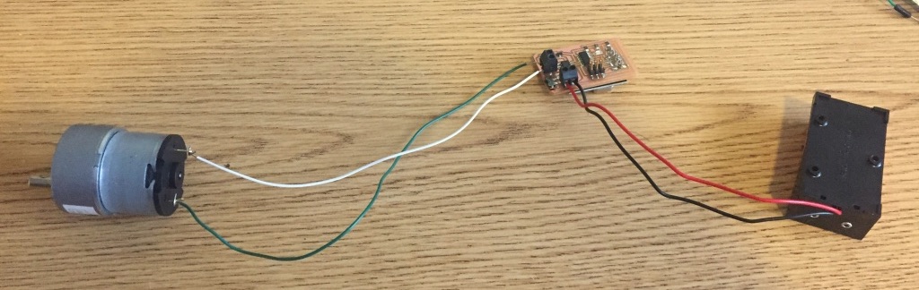
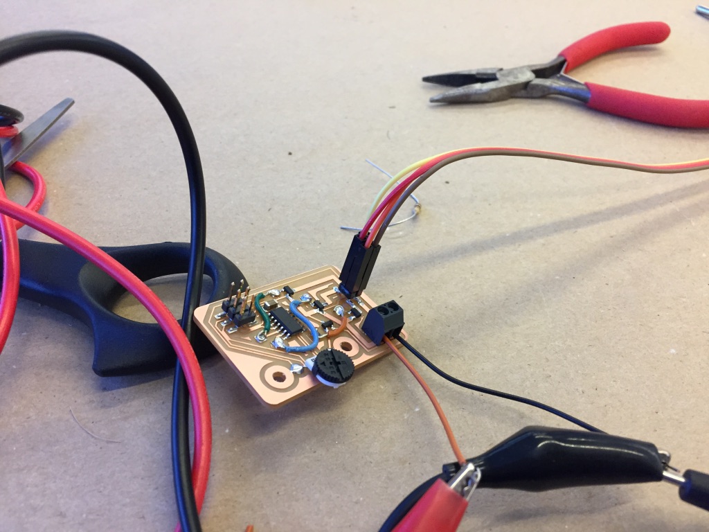
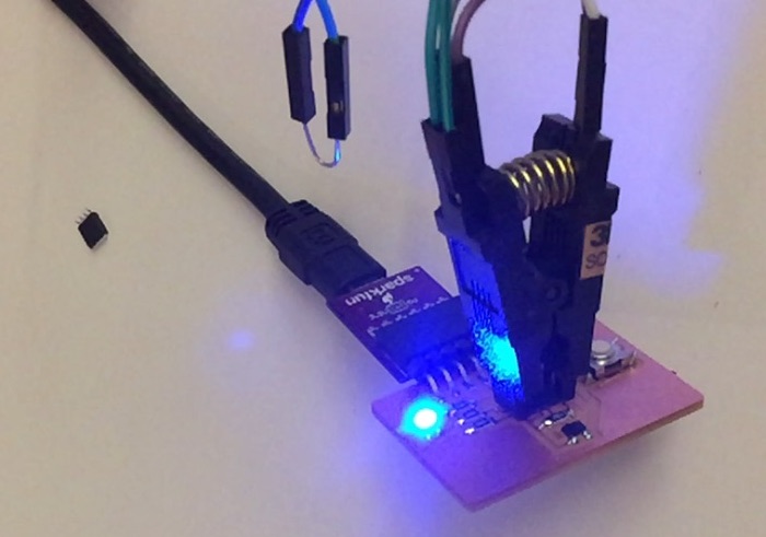
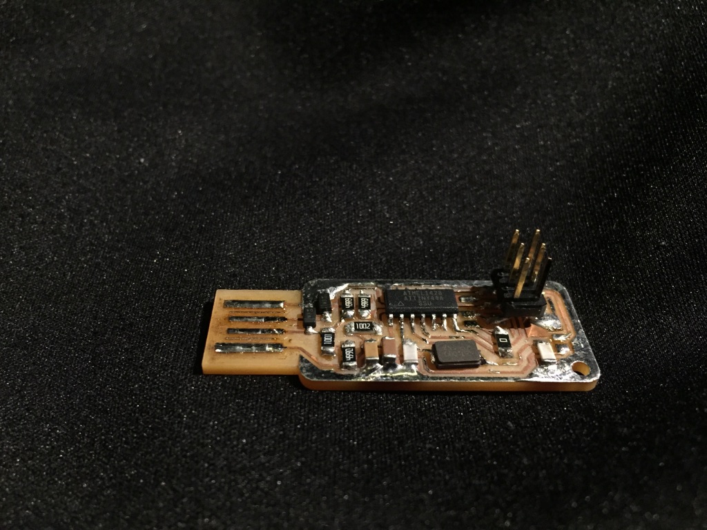
Here’s what a single one wired up to a battery and motor looks like. This represents the electrical core of the anchors that are mounted on 3 corners of the room.
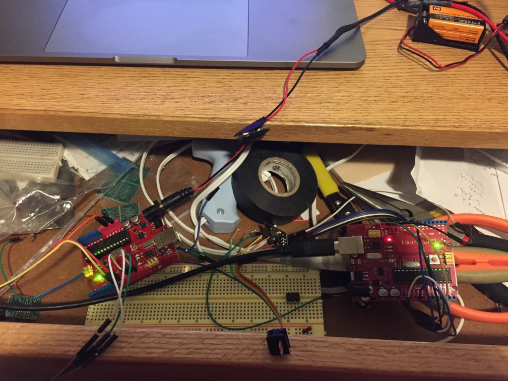
To debug the system, I connected an ordinary Aduino UNO to the nRF24L01+ to send messages back and forth to the attiny devices.
Week 11
Interface
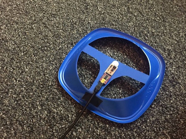
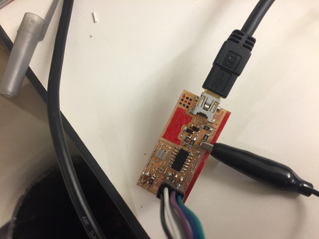
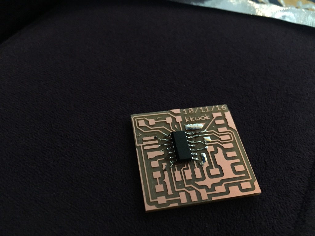
I didn’t have time to make a new circuit board for this week, so I used a serial accelerometer board that I had milled and populated from a few weeks ago.
I heard about the Chrome serial API and I was curious what could be done with it.
It’s actually quite a simple API
chrome.serial.connect(path, {
    bitrate: 9600,
    bufferSize: 10
}, this.onConnectComplete.bind(this))
I based it on the “ledtoggle” example found here.
One mildly concerning thing is the big notice on the top of the API documentation page
Important: Chrome will be removing support for Chrome Apps on Windows, Mac, and Linux. Chrome OS will continue to support Chrome Apps. Additionally, Chrome and the Web Store will continue to support extensions on all platforms. Read the announcement and learn more about migrating your app.
It’s probably likely that the API is still accessible to extensions (where there’s a pretty minor difference between extensions and apps). But just perhaps to future readers, this current incarnation of the code probably has a finite bounded shelf life.
Following the serial protocol used in Neil’s ADXL343 example found here: hello.ADXL343.c, the data consists of a set of packets framed by the sequence [1,2,3,4], followed by six bits representing the data (using two bytes for each value).
The “ledtoggle” code comes with some code to detect line breaks in main.js.
var index;
while ((index = this.lineBuffer.indexOf('\n')) >= 0) {
    var line = this.lineBuffer.substr(0, index + 1);
    this.onReadLine.dispatch(line);
    this.lineBuffer = this.lineBuffer.substr(index + 1);
}
I just replaced the '\n' with '\x01\x02\x03\x04' to treat the framing code as a line break. Then to parse it, I modified the read line handler.
connection.onReadLine.addListener(function(line) {
    var bb = new Uint8Array(str2ab(line));

    var z1 = bb[bb.length - 1];
    var z0 = bb[bb.length - 2];
    var y1 = bb[bb.length - 3]
    var y0 = bb[bb.length - 4]
    var x1 = bb[bb.length - 5]
    var x0 = bb[bb.length - 6];

    var x = x0+255*x1
    if (0x8000 & x) x = -(0x10000-x);

    var y = y0+255*y1
    if (0x8000 & y) y = -(0x10000-y);

    var z = z0+255*z1
    if (0x8000 & z) z = -(0x10000-z);

    document.getElementById('x').innerText = x
    document.getElementById('y').innerText = y
    document.getElementById('z').innerText = z
});
This got me to a pretty spartan interface:
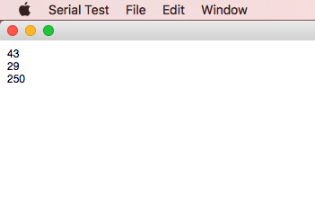
I added something that plots the values:
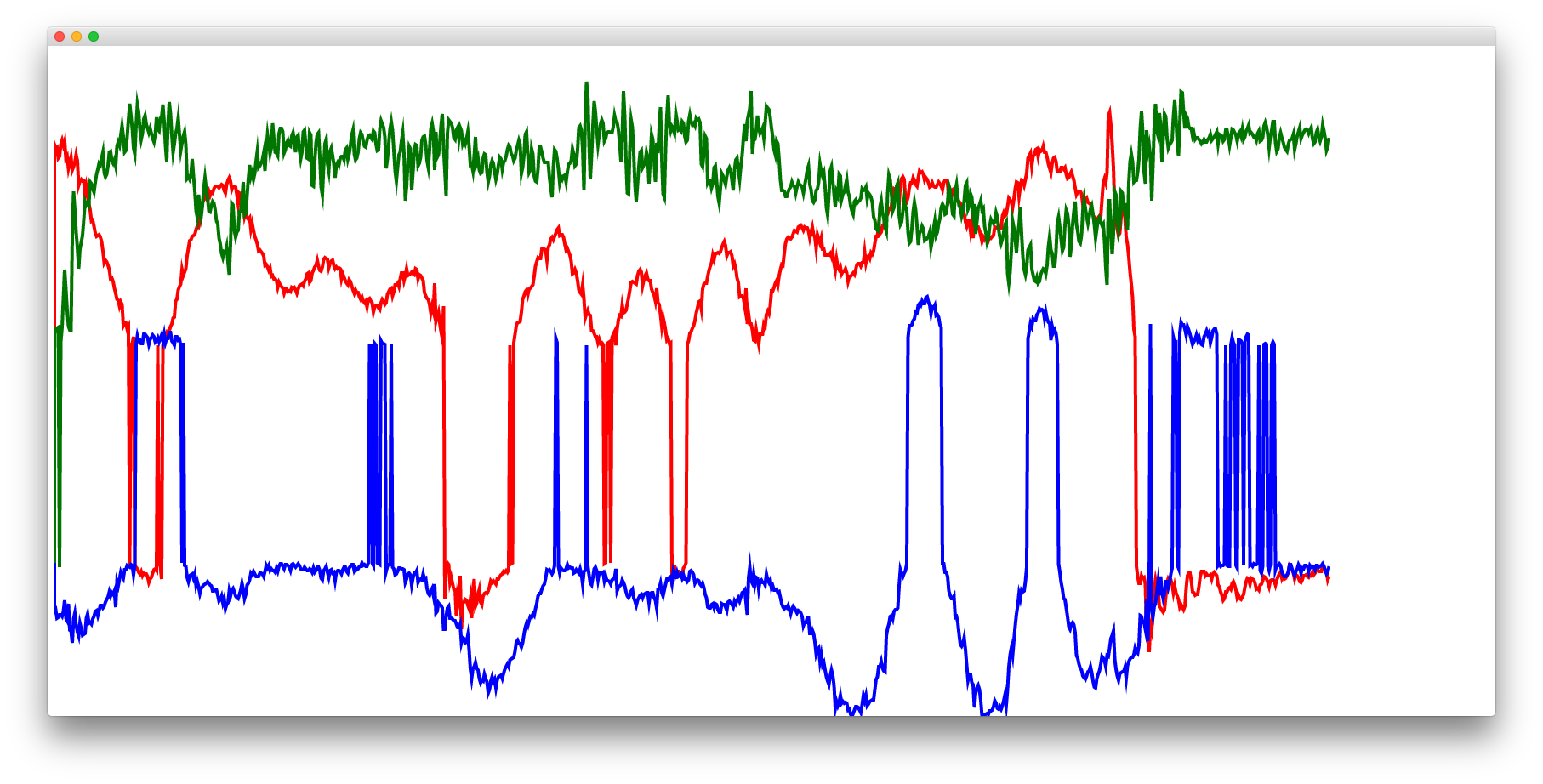
Then I noticed that whenever it crosses the origin, there’s a large discontinuity. I think there may be something wrong with the way I’m decoding the signed two-byte integers.
To use the chrome serial port API you have to load your app as a chrome extension. It’s not necessary to use Node or NPM.
You can download my code from here, and stick it into a folder on your desktop
Then navigate to chrome://extensions, enable “Developer Mode” , and click “Load unpacked extension…” and locate that folder.
There should be a thing that appears named “Serial Test” and you should be able to hit the “Launch” link to open it up. It should open up a blank window— right click on it and click “Inspect Element” if you want to open up the developer console.
You’ll probably need to modify the first line of main.js:
const DEVICE_PATH = ‘/dev/tty.usbserial-A4013FV1’;
To reflect the path to your serial device.
Week 10
Output
This week I want to drive a strip of LED lights.
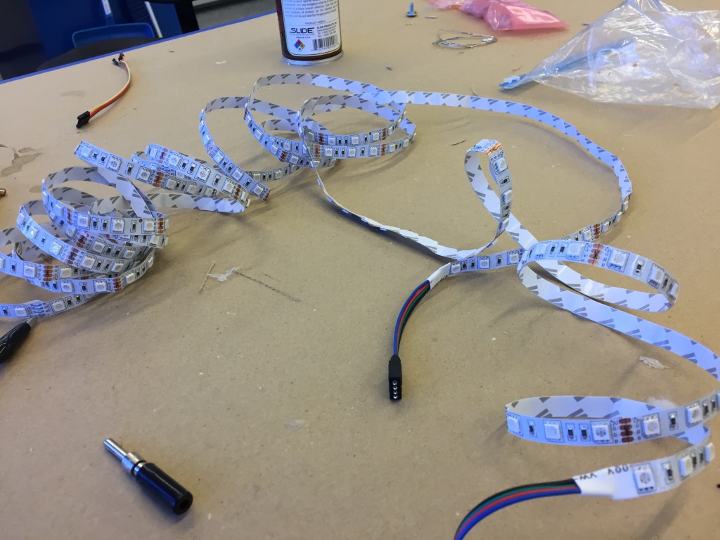
I got these LED strips from eBay for about $8.
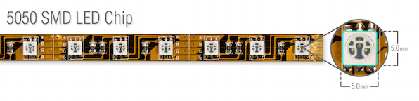
The 5050 RGB led strips consist of several segments wired in parallel. Each of these segments consists of RGB LEDs wired in series, with the appropriate resistors. As such they’re not individually addressable.
These strips have a common anode (confusingly this is represented by the black wire), and any of the colors is triggered by pulling it to ground.
A single strip of these lights can use up to 24W (12V * 2.04A).
I’m using a N-MOSFET to supply the current.
I gave up on routing certain wires so I added a bunch of jumpers by treating them as vias.
I wanted to have space for a potentiometer to change the color hue, but it looked like the component footprint was wrong.
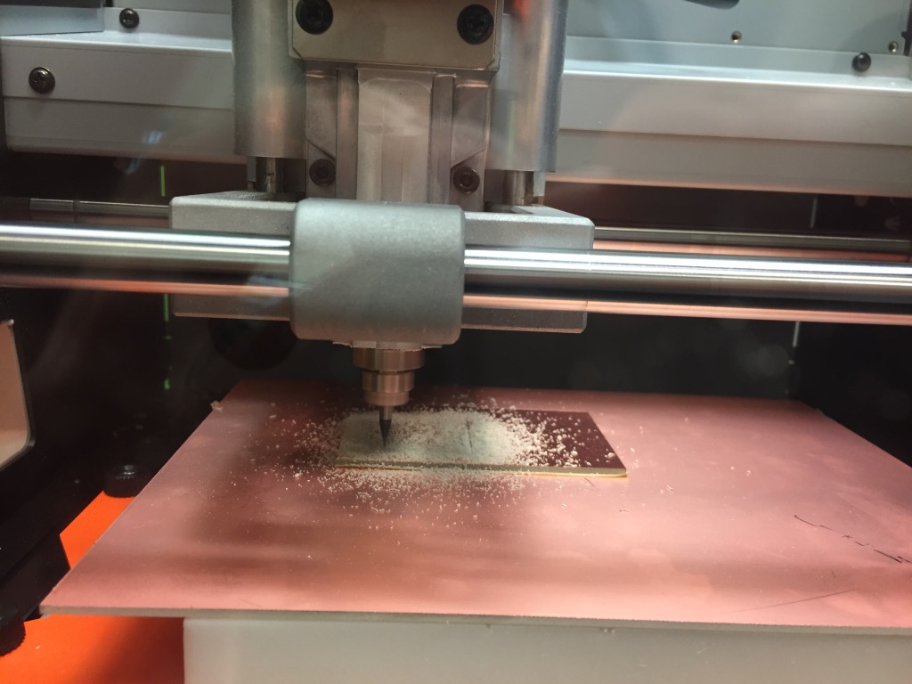
I milled it out on the Roland SRM-20
I placed the components and soldered them using solder paste.
I connected it to a lab power supply
It didn’t work.
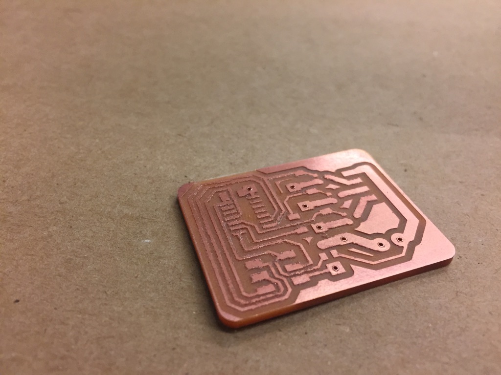
I redesigned the board, this time I wanted to use the entire back of the board as a ground plane.
It was really easy to add vias in Eagle. I drew a big rectangular block on the bottom layer to act as the ground plane wire. Then whenever I needed to wire something to ground, I switched the active plane to the bottom layer and clicked anywhere and a new via was created.
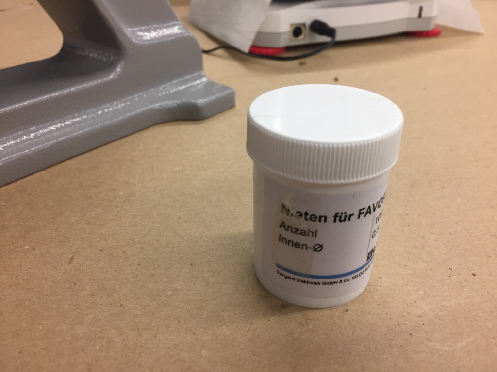
The rivets for creating the vias comes in this little medicine-bottle sized container with German labels. The rivets are actually really small.
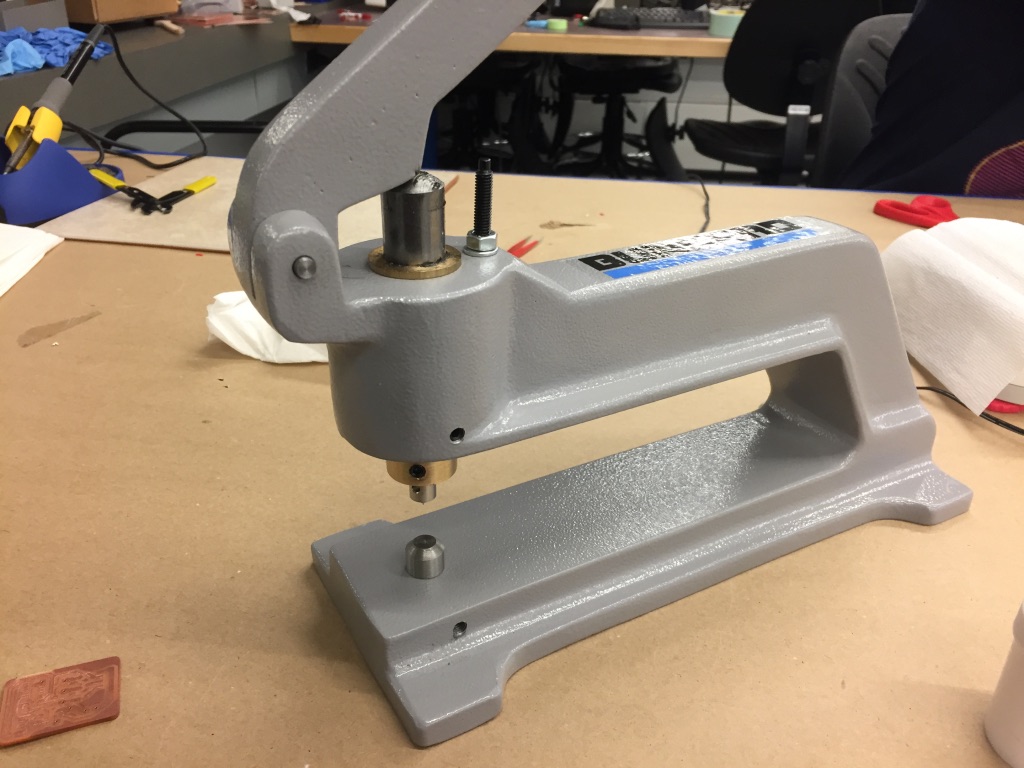
We use this thing to smash the rivets into place.
Week 9
Composites
This week I’m making a hardhat.
I designed a model in Rhinoceros. First I tried doing something which was fairly complicated— using lots of non-planar curves, but I encountered a lot of trouble making it into solid.
So I started from scratch and built a much simpler model— intersecting an ellipsoid with an extruded ellipse.

There are a few people waiting in line to use the CNC router to make their part in the pink building insulation foam, so I figured that I would try to do something else.
The resolution isn’t going to be particularly good with the composites anyway, so I figured I might as well try to make a press-fit mold out of cardboard.

I converted the model into a series sheets with Autodesk’s 123D make software.
Here’s the cardboard— I had to cut extra sheets because the first run ended up too small to neatly fit together.
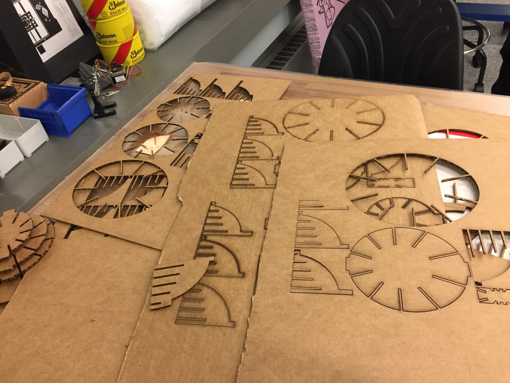
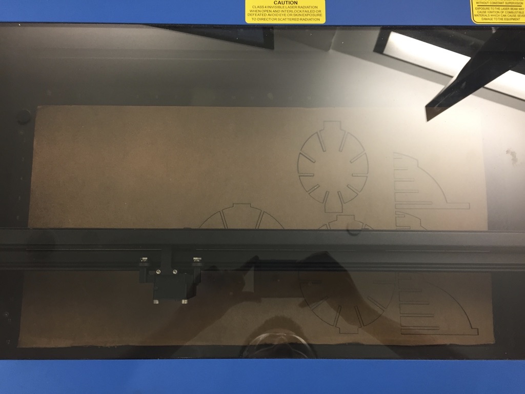
I cut it out with the laser cutter, and assembled the object. It was really difficult so I ended up cutting off from the sides of the cardboard with scissors.
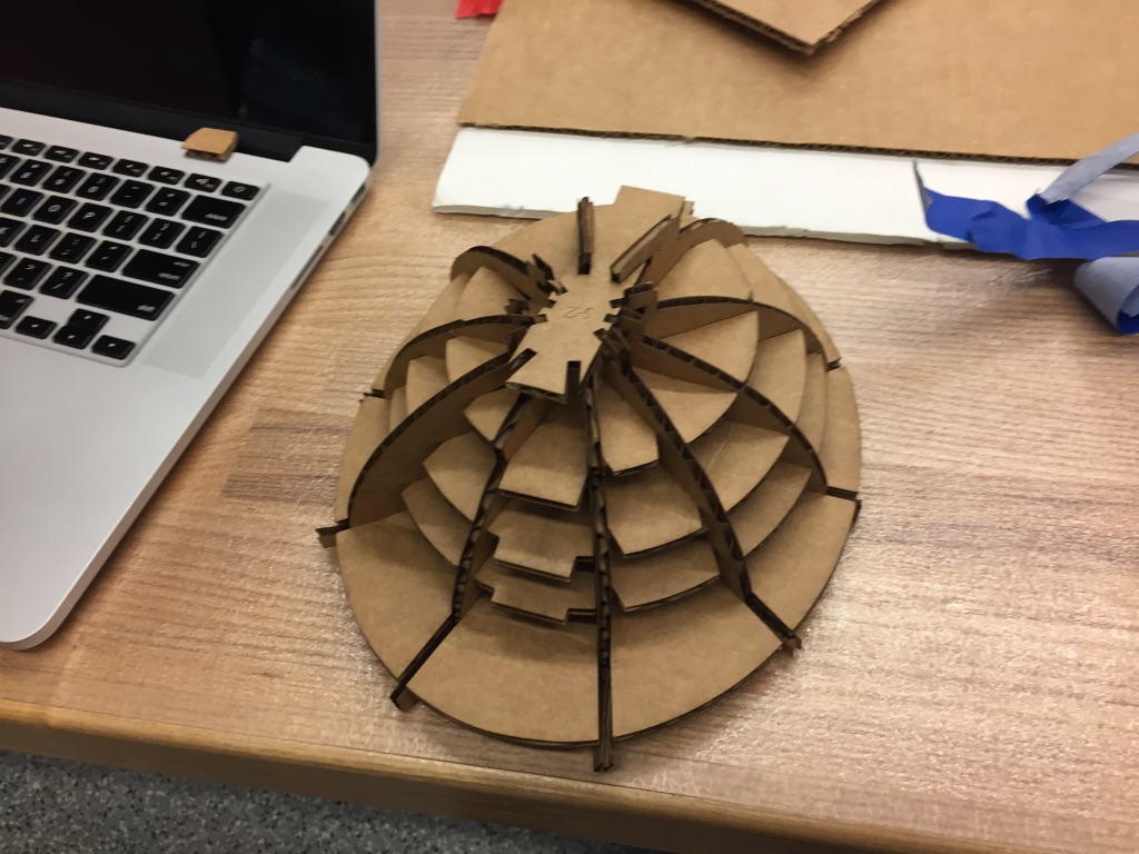
I stuffed it with paper towels so that it’d be hopefully more rigid in the face of a vacuum, but the cardboard is already reasonably stiff.
I wrapped it with the aluminum foil.

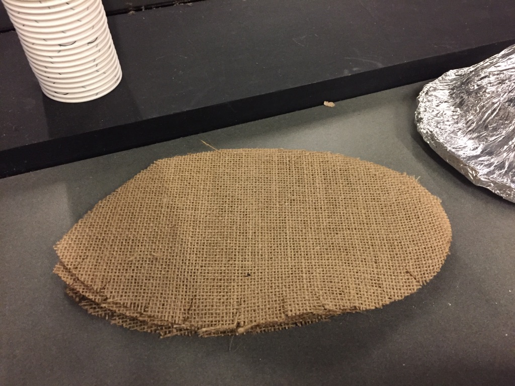
I cut a piece of burlap that would fit by hand with scissors.
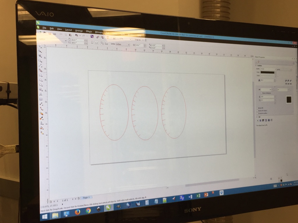
Then I drew the design with Corel draw and had it cut several times on the laser cutter.
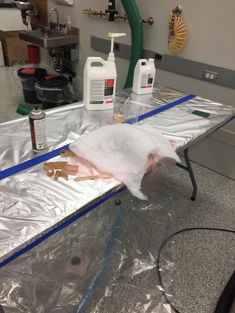
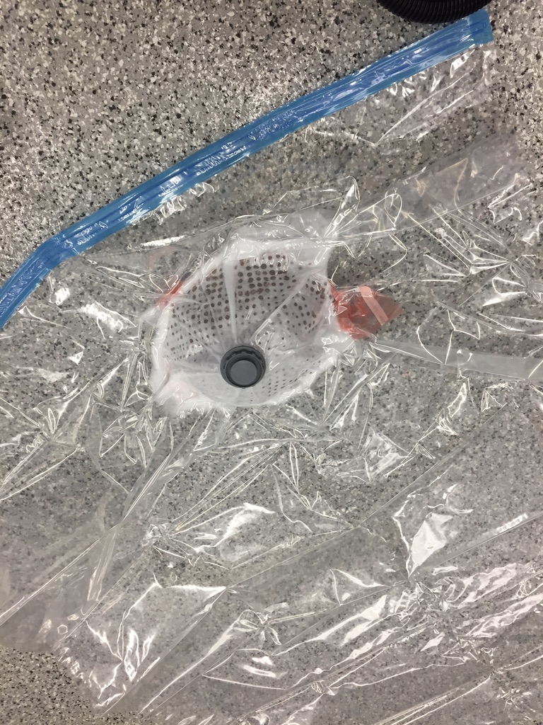
So I added lots of mold release, and then the requisite layers of bleeder and breather, and shoved it into the vacuum seal bag.
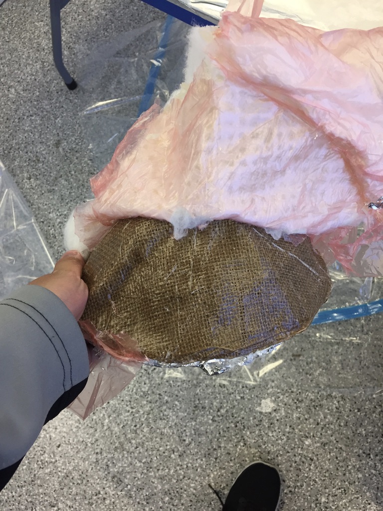
The next day, I came back and pulled out the hat. It was pretty difficul to get all the bits of foil and cotton off, but it seemed alright in the end.
Week 8
Input Devices
I didn’t include an ISP because I wanted to experiment with using a clip instead.
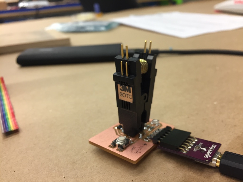
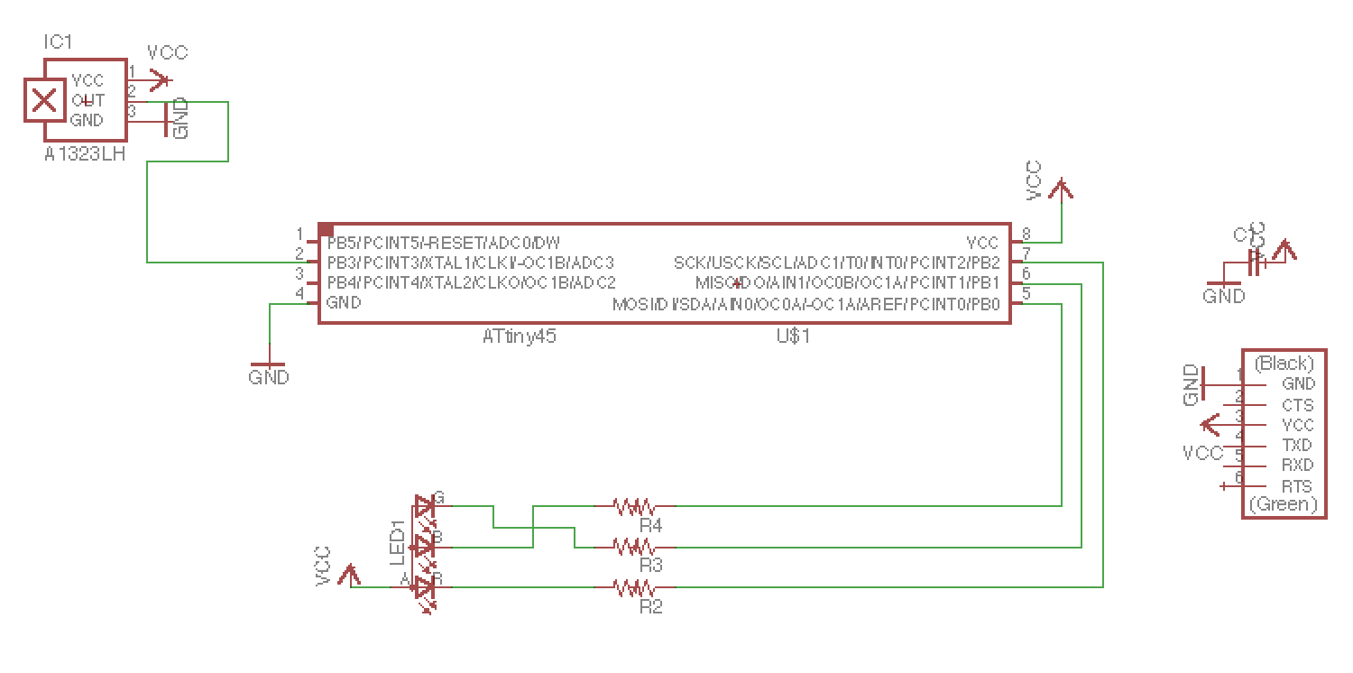
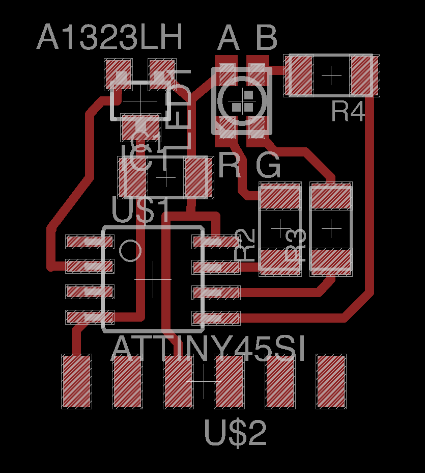
I made a board with a hall effect sensor, an RGB LED, and a push-button switch.
Unfortunately I don’t actually have a picture of the original board schematic.
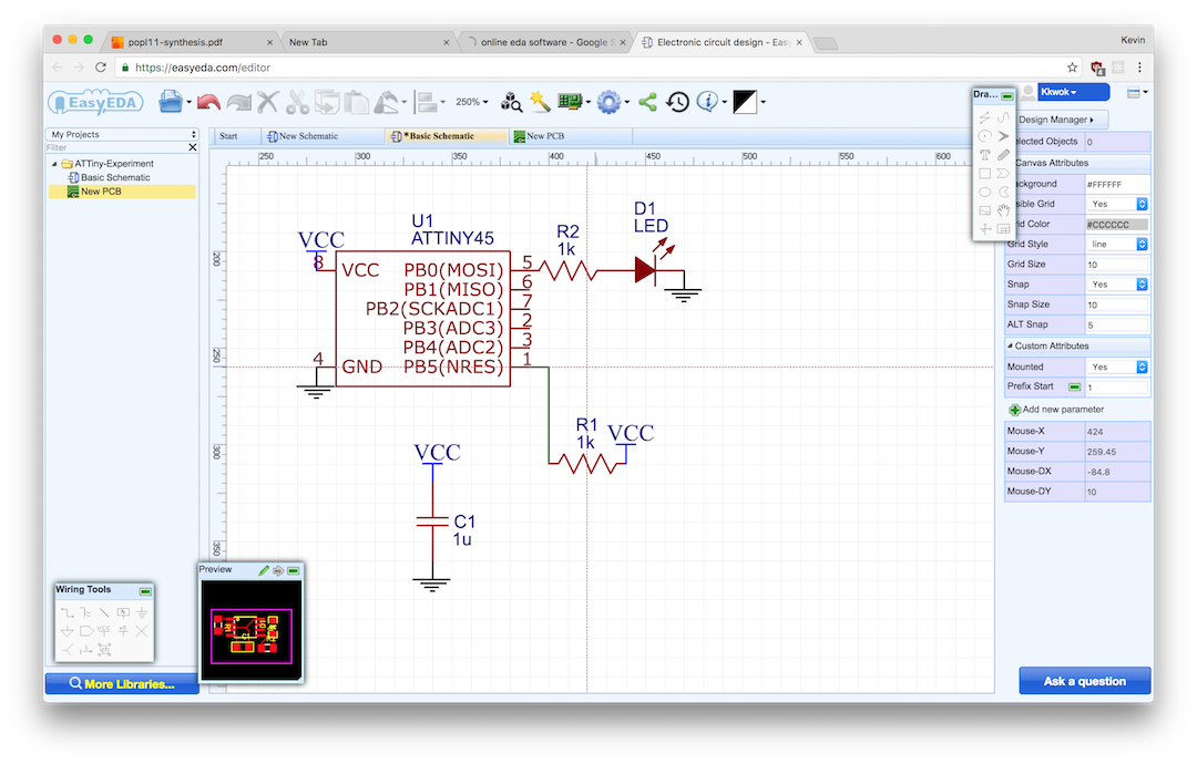
I also played around with using EasyEDA, which is a web application instead of Eagle— but I didn’t finish building anything with it.
Anyway, here are the pictures of the traces and the mask:
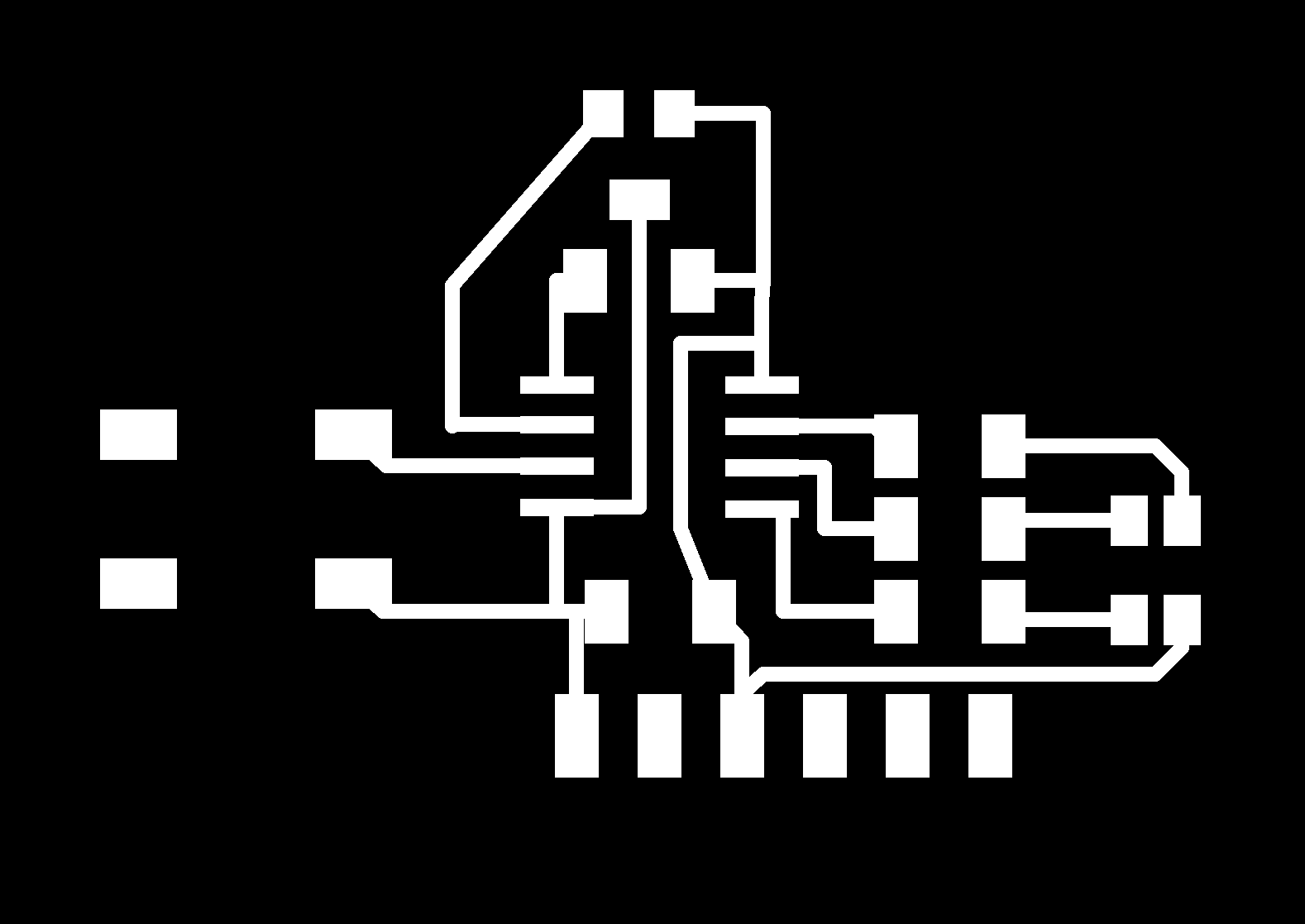

I milled it out using the mods software on an Roland SRM-20.
I populated the board, and tried programming it, and it didn’t work.
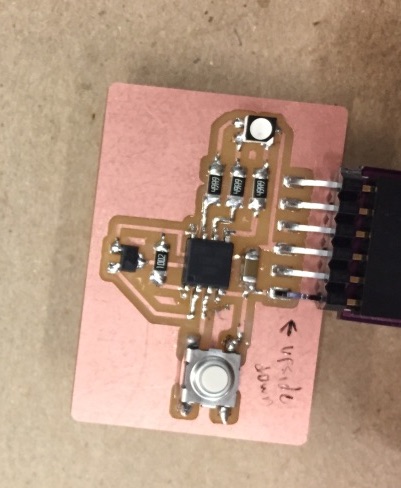
I very carefully attached the hookup wires to the chip again, and tried programming a bare chip.
But to do so, the ISP needs to provide power to the chip:
I took an alligator clip and attached to the side rail of the FabISP, and connected that with the V pin of the ISP.
This worked, but it was incredibly unreliable— so I sanded down the tip of the clip so that it’d make better electrical contact.
I wrote some code which would change the color according to the magnetic field: switching between red and blue depending on the field direction, with brightness corresponding to field intensity.
Week 7
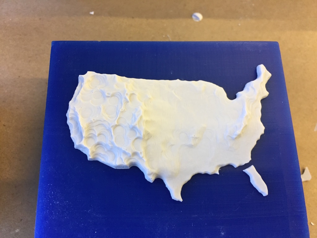
Molding and Casting
This week, I didn’t try to be particularly brave and built an object which could be constructed with a single-sided mold. At the same time, I wanted to make an object which could use the resolution afforded by the CNC mills.
I woke up in the middle of the night with the idea that I could make some sort of topographical map. I grabbed my laptop and started looking into finding the elevation data.
I found that CGIAR, the Consultative Group for International Agricultural Research, provides the result elevation surveys in a format called “SRTM” at 90m resolution.
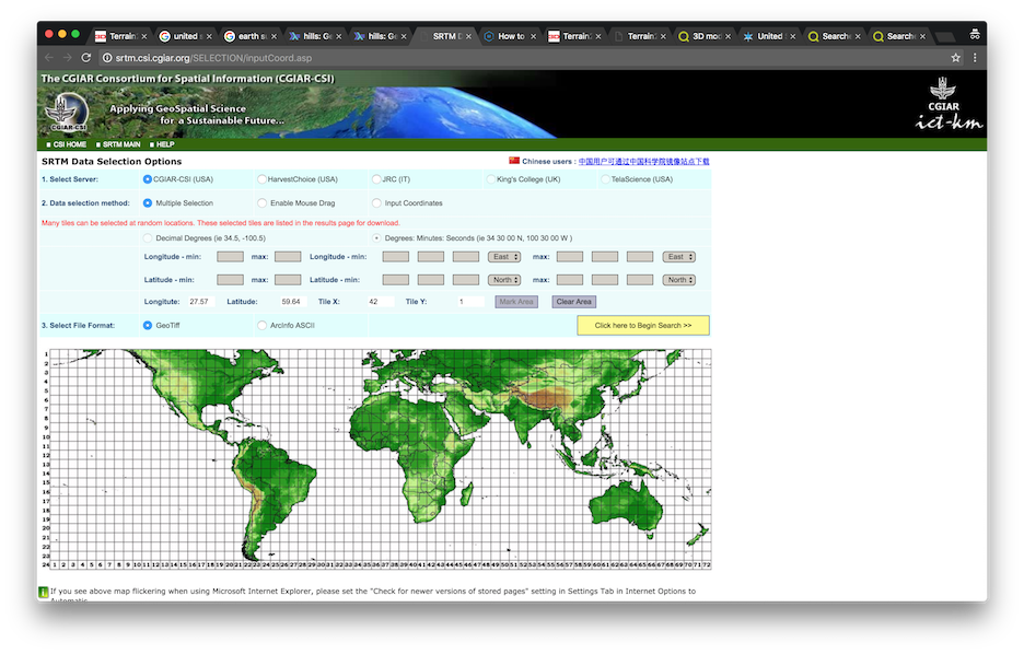
I tried downloading all the tiles that covered the United States, but that ended up being too much data. I found another dataset which was resampled to 1km resolution.
I used some software called SimpleDEM, which got pretty close to what I wanted— but I wanted to cut the map out at the border of the country.
So I tried to write some code in Mathematica which would display the elevation data— since it’s all built-in with the GeoElevationData function.
The first thing I noticed was how arbitrarily the coastlines seem to be placed. There isn’t a precipitous drop in elevation by the coastline: just a mostly linear grade that happens to intersect with the sea levels. The noticable edge happens a few hundred miles away from the coast— at the continental shelf.
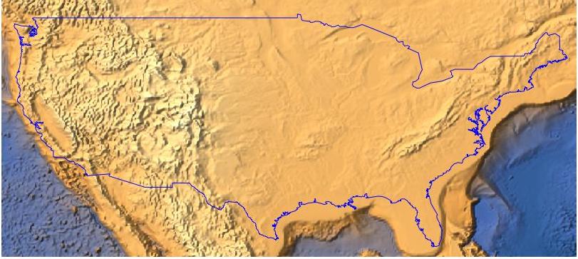
I just intersected the elevation data with the country boundary, adding an offset for the interior of the country, and scaled them down to the bit depth of an image. I then exported the image— a heightmap.
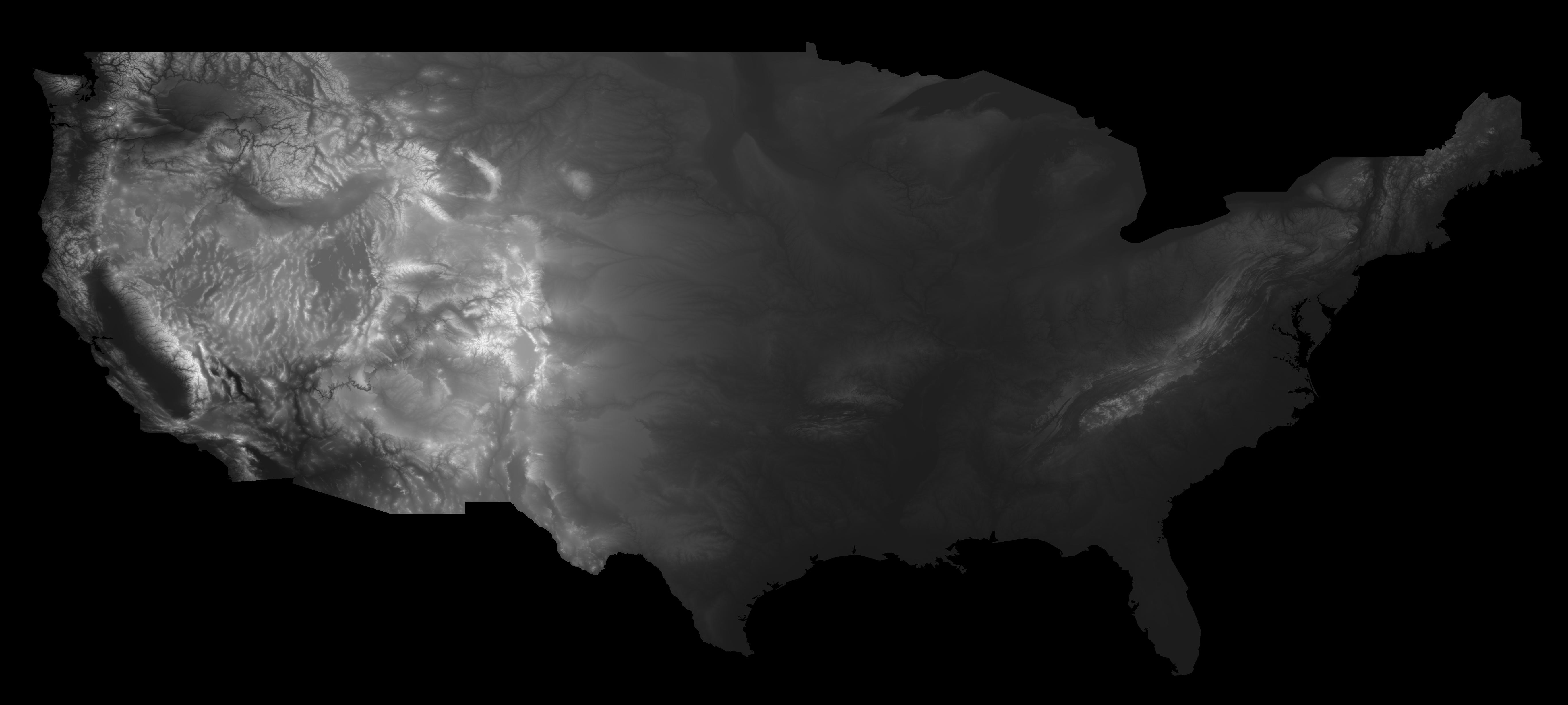
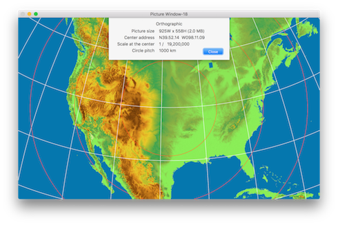
Unfortunately, this image is drawn with a Mercator projection— which stretches out the width of the United States, and makes the boundary between Canada and the US seem like a flat line. I couldn’t find a good way to apply an Orthographic projection to an image within Mathematica.
So I opened up the image in Photoshop, overlaid a semi-transparent orthographic projection and used Photoshop’s cage warp to squish it into what looked to be the right shape.
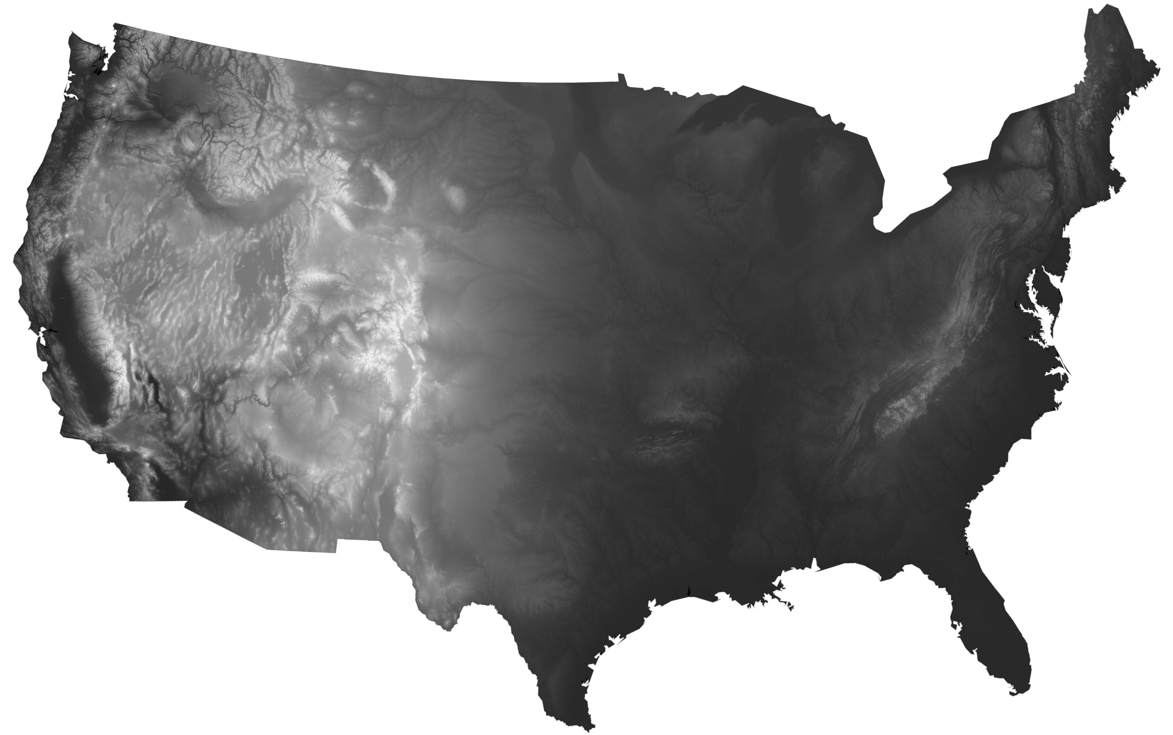
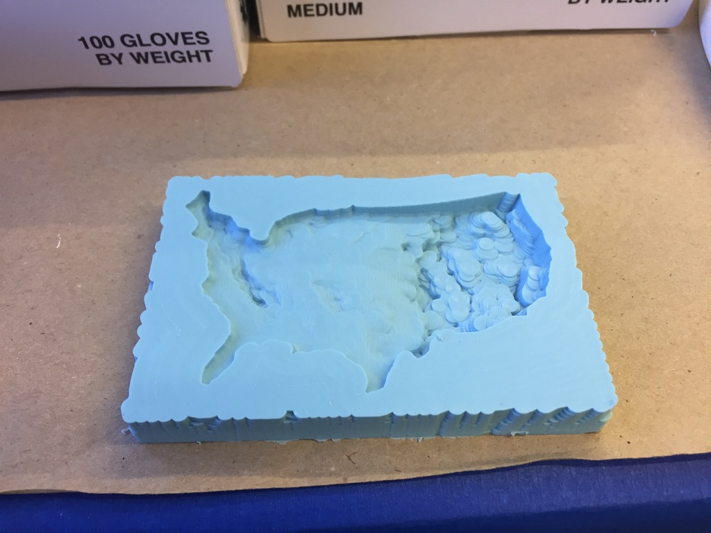
I then tried importing the image as a heightmap into Rhinoceros, which has a Heightfield command for importing depth maps. The immediate thing I noticed was how mountainous the west of the US is compared to the east.
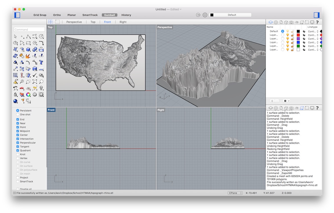
I then exported the resulting surface as an STL for import into Fusion 360, which has a nice built-in raytracing renderer.

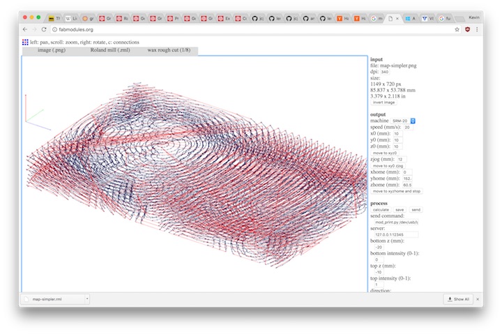
Rather than converting the object into a mesh for import into fabmodules, I tried to just import the heightmap directly.
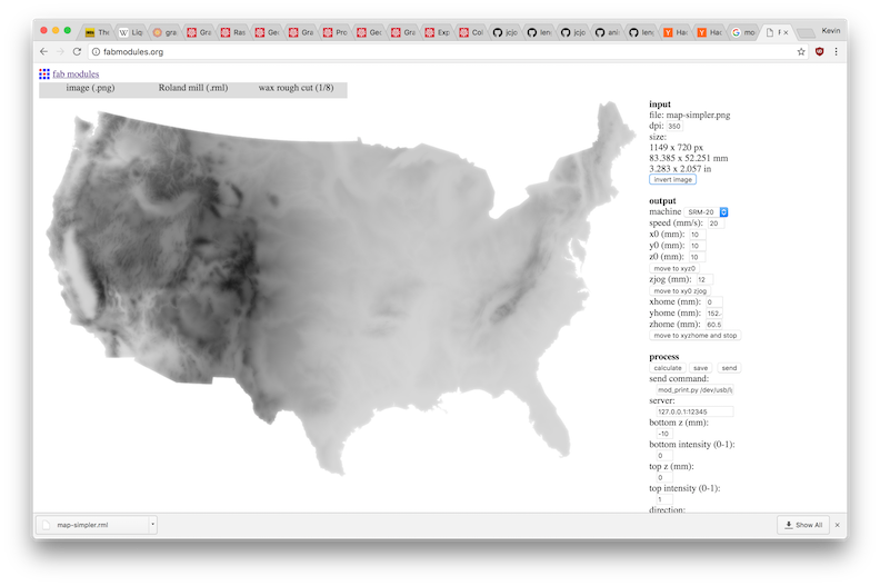
It worked pretty seamlessly. I just had to configure the bottom z to the appropriate cut depth.
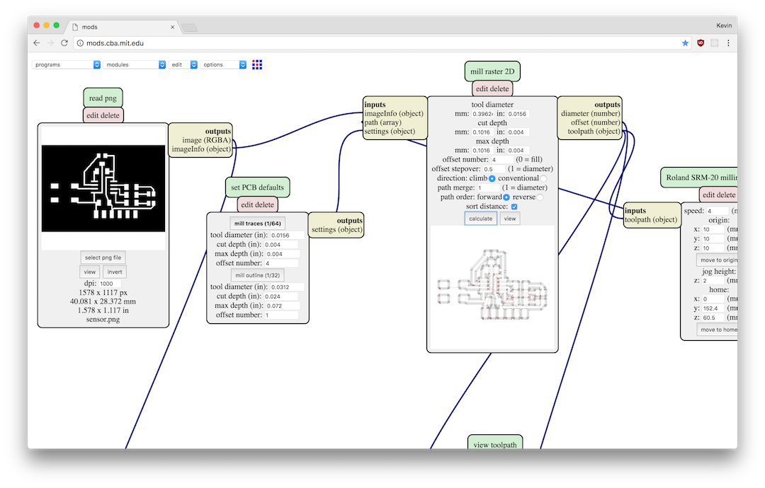
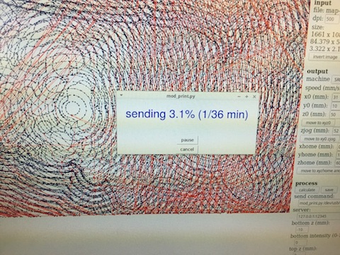
The software communicates with the Roland SRM-20 through a NodeJS bridge mod_server.js which is notably different from the one used by the new mods interface.
What mod_server.js does is it actually exposes shell access through WebSocket connections. When a toolpath is sent, it simply executes a command such as mod_print.py /dev/usb/lp0....
Because of this, we need to add mod_print.py to the system PATH (or to override the environment variable before calling node mod_server.js).
Anyway here’s the generated toolpath (which took a while to generate)
Here’s the rough cut getting machined:
The finishing pass:
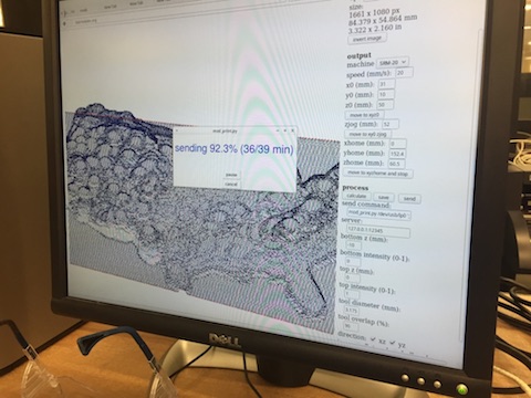
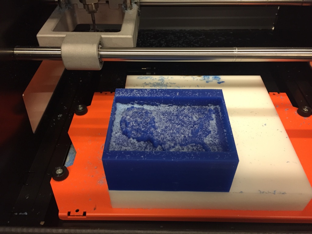
The wax:
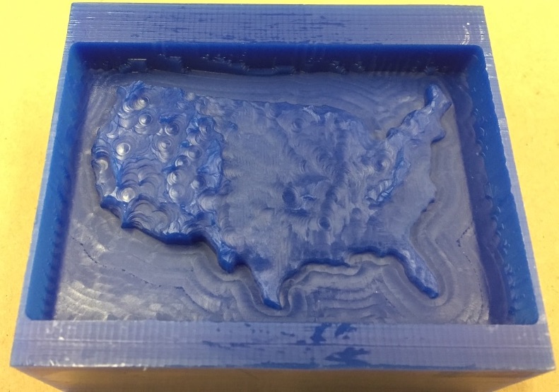
The 1/8th inch endmill was too big to really encode much of the finer detail.
Week 6
Embedded Programming
This week didn’t really involve physical objects much, so it’ll be fairly light on photos and heavier on screenshots and code snippets.
For this week, I programmed the circuit that I designed two weeks ago.
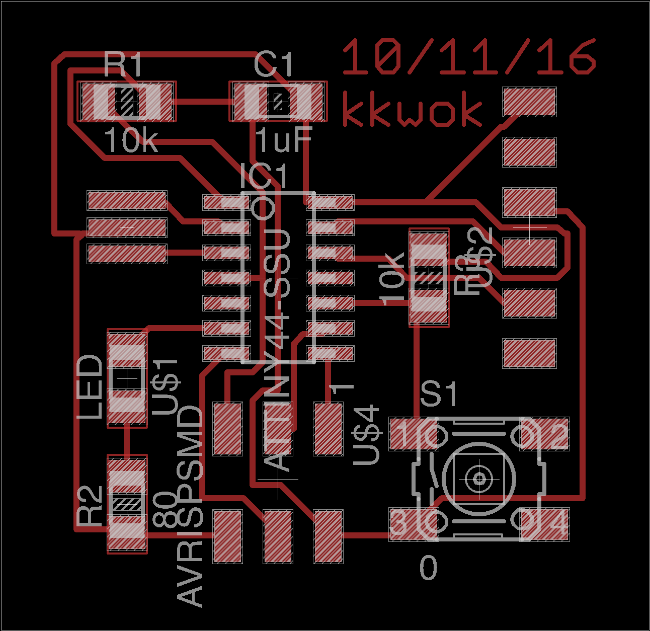
I hooked it up to the FabISPKey programmer, and one of the FTDI adapters, and attempted to upload a program with the provide Makefile.
PROJECT=hello.ftdi.44.echo
SOURCES=$(PROJECT).c
MMCU=attiny44
F_CPU = 20000000

CFLAGS=-mmcu=$(MMCU) -Wall -Os -DF_CPU=$(F_CPU)

$(PROJECT).hex: $(PROJECT).out
    avr-objcopy -O ihex $(PROJECT).out $(PROJECT).c.hex;\
    avr-size --mcu=$(MMCU) --format=avr $(PROJECT).out

$(PROJECT).out: $(SOURCES)
    avr-gcc $(CFLAGS) -I./ -o $(PROJECT).out $(SOURCES)

program-bsd: $(PROJECT).hex
    avrdude -p t44 -c bsd -U flash:w:$(PROJECT).c.hex

program-dasa: $(PROJECT).hex
    avrdude -p t44 -P /dev/ttyUSB0 -c dasa -U flash:w:$(PROJECT).c.hex

program-avrisp2: $(PROJECT).hex
    avrdude -p t44 -P usb -c avrisp2 -U flash:w:$(PROJECT).c.hex

program-avrisp2-fuses: $(PROJECT).hex
    avrdude -p t44 -P usb -c avrisp2 -U lfuse:w:0x5E:m

program-usbtiny: $(PROJECT).hex
    avrdude -p t44 -P usb -c usbtiny -U flash:w:$(PROJECT).c.hex

program-usbtiny-fuses: $(PROJECT).hex
    avrdude -p t44 -P usb -c usbtiny -U lfuse:w:0x5E:m

program-dragon: $(PROJECT).hex
    avrdude -p t44 -P usb -c dragon_isp -U flash:w:$(PROJECT).c.hex
But for some reason, it didn’t work.
Shortly afterward, I accidentally maimed my board. The strain relief on the FTDI header was off the board, and I had put too much presure on it and ended up ripping it off the board along with half of the traces.
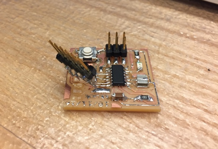
I re-made the board this time, with a larger outline so that the black plastic stayed on the surface of the board.
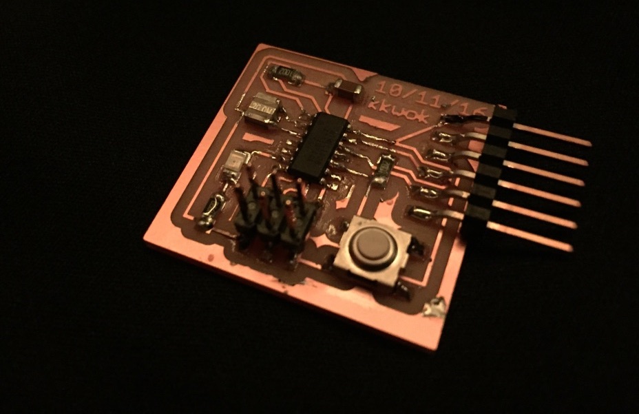
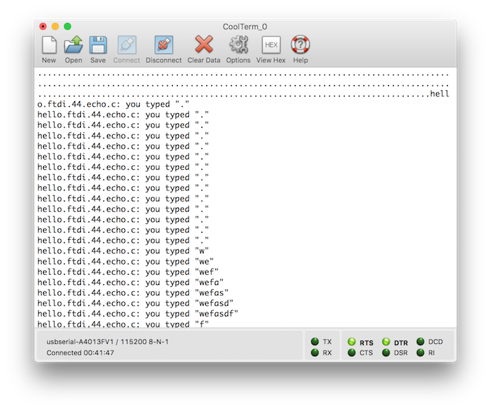
In the mean time, while the board was milling, I tested out one of the echo boards laying around the lab which didn’t have any peripherals attached. I successfully managed to program it and see the results in CoolTerm.
I was playing around with an Arduino LilyPad a few years ago, which needs to be programmed with FTDI, so I had an FTDI adapter already.

It didn’t quite work out-of-the-box (unlike the FTDI cable in lab), I had to first install FTDI drivers for Mac.
Blinking the LED
Once my new board worked, I tried to blink the LED.
#include <avr/io.h>
#include <util/delay.h>

#define LEDPORT PA7

int main(void) {
    // http://maxembedded.com/2011/06/port-operations-in-avr/
    // our LED is connected to LEDPORT
    DDRA |= (1 << LEDPORT);

    while (1) {
        PORTA ^= (1 << LEDPORT); // toggle LED
        _delay_ms(1000); // delay for 1 second
    }
}
I looked into the schematic in Eagle, and noticed that I had connected the LED to port PA7.
This code should ostensibly toggle the light every second, but it was actually something closer to 8 seconds. After a bit of fiddling around, it looks like it might have been because of the clock prescaler because adding the following two lines ended up fixing it.
// set clock divider to /1
CLKPR = (1 << CLKPCE);
CLKPR = (0 << CLKPS3) | (0 << CLKPS2) | (0 << CLKPS1) | (0 << CLKPS0);
Writing Assembly
I took 6.115 (Microcomputer Electronics Lab) about 2 years ago, so I had some long and not-so-fond memories of writing for microcontrollers in assembly.
First I tried loading the Intel HEX file into a disassembler, which is an intermediate file in the Makefile toolchain.
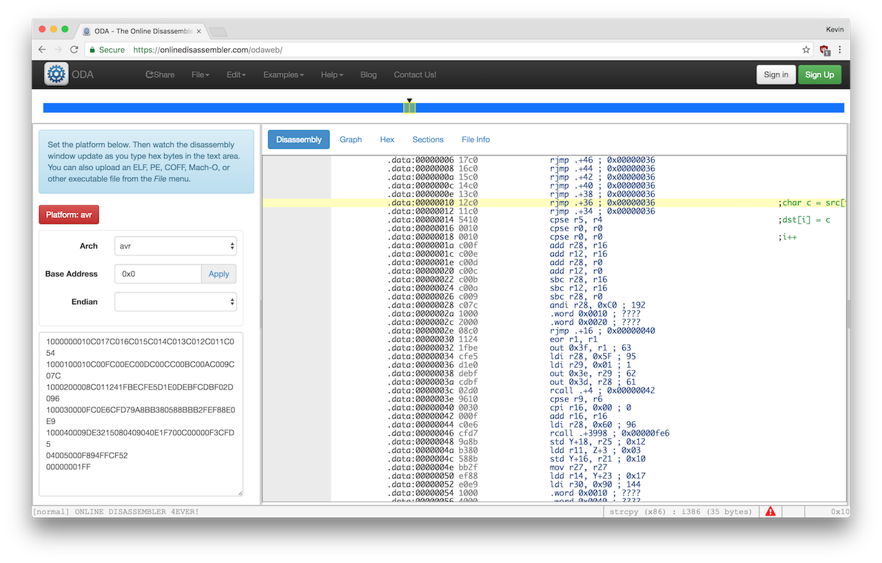
Then Anish very helpfully noted that that’s unnecessary because GCC has a -S option which outputs assembly instead of a binary.
I looked into the assembly generated by GCC and then cleaned it up to make the minimal code for blinking an LED:
main:
	sbi 0x1a, 7 ;  Set Bit in I/O Register

.repeat:
	in r24, 0x1b ;
	subi r24, lo8(-(-128))
	out 0x1b, r24

	rjmp .repeat
(This code actually blinks at essentially the clock rate of the processor which is kind of insanely fast so you can’t actually see it blinking)
Then I tried to assemble it into a binary to program the device, with avr-as, where as is the GCC assembler.
I was trying to get it to program, but it wasn’t working.
It turns out that you need to use avr-ld, the linker, to convert the object files that are produced by as into binary.
So the new (working) Makefile for programming an ATTiny with assembly is as follows:
PROJECT=test
SOURCES=$(PROJECT).asm
MMCU=attiny44

$(PROJECT).hex: $(PROJECT).out
    avr-objcopy -O ihex $(PROJECT).out $(PROJECT).c.hex;\
    avr-size --mcu=$(MMCU) --format=avr $(PROJECT).out

$(PROJECT).obj: $(PROJECT).asm
    avr-as -mmcu=$(MMCU) -o $(PROJECT).obj $(PROJECT).asm

$(PROJECT).out: $(PROJECT).obj
    avr-ld -o $(PROJECT).out $(PROJECT).obj

program-bsd: $(PROJECT).hex
    avrdude -p t44 -c bsd -U flash:w:$(PROJECT).c.hex

program-dasa: $(PROJECT).hex
    avrdude -p t44 -P /dev/ttyUSB0 -c dasa -U flash:w:$(PROJECT).c.hex

program-avrisp2: $(PROJECT).hex
    avrdude -p t44 -P usb -c avrisp2 -U flash:w:$(PROJECT).c.hex

program-avrisp2-fuses: $(PROJECT).hex
    avrdude -p t44 -P usb -c avrisp2 -U lfuse:w:0x5E:m

program-usbtiny: $(PROJECT).hex
    avrdude -p t44 -P usb -c usbtiny -U flash:w:$(PROJECT).c.hex

program-usbtiny-fuses: $(PROJECT).hex
    avrdude -p t44 -P usb -c usbtiny -U lfuse:w:0x5E:m

program-dragon: $(PROJECT).hex
    avrdude -p t44 -P usb -c dragon_isp -U flash:w:$(PROJECT).c.hex
Interpreters
The ATTiny has too little memory to run MicroPython or MicroLisp, and there aren’t any JS interpreters which can run on the device.
I did however try to run a Brainfuck interpeter, which should have been able to fit in theory, but I wasn’t successful.
Week 5
Building A Big Maze
I was really struggling to come up with something to make, but found inspiration in the form of a small 3D-printed maze box a friend was showing around. I took the idea and scaled it up by an order of magnitude, and changing the form factor from a box to a hemisphere.
The first step was to make the maze. I found a website www.mazegenerator.net which generates radial mazes that you can export as SVG.
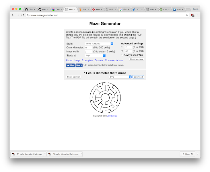
I downloaded the mazes and imported them into Adobe Illustrator. I selected the line segments that composed that maze and changed the font weight so it’d be reasonable to mill. I also changed the line caps to “round” for a nice round aesthetic.
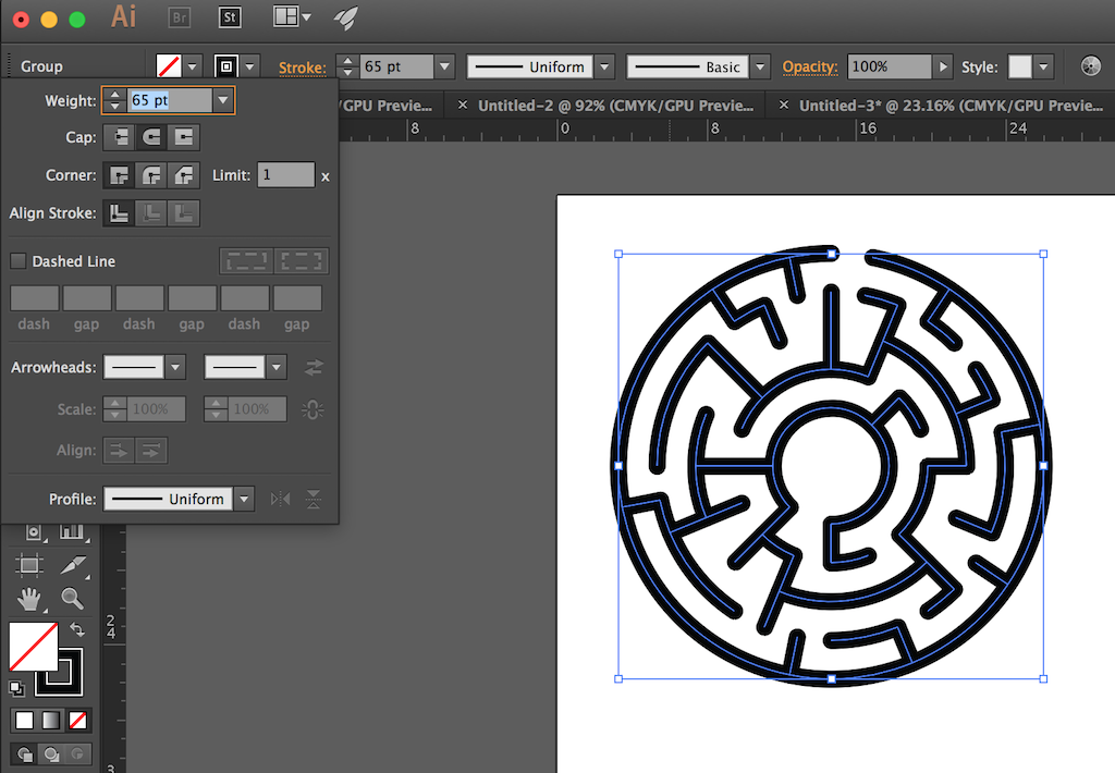
However, in spite of looking pretty close, the shape isn’t yet in an acceptable format because it’s a big set of line segments (also, we want to be able to fillet the remaining corners).
So I used the Convert to Outline transformation to take that set of lines and turn it into single giant SVG path. I changed the fill to none and the stroke to a hairline black. I selected all the control points and then set a corner radius, which has the effect of filleting everything.

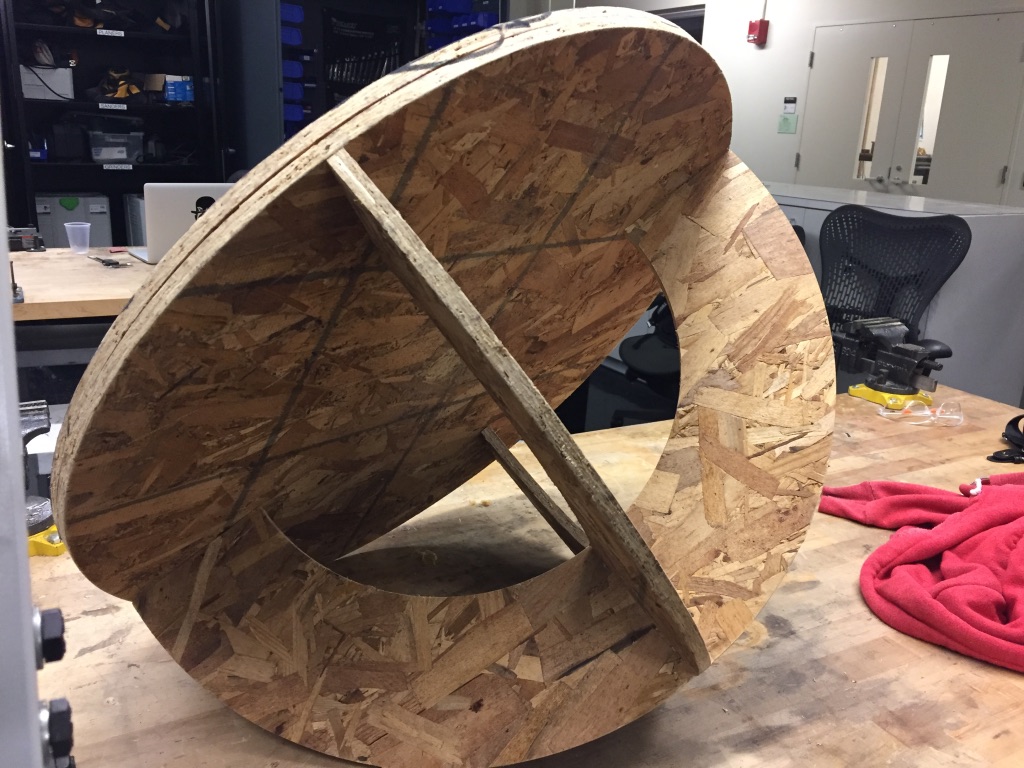
I wanted a hemispherical base so the thing could be pushed around, so I added two press-fit semicircles to the design.
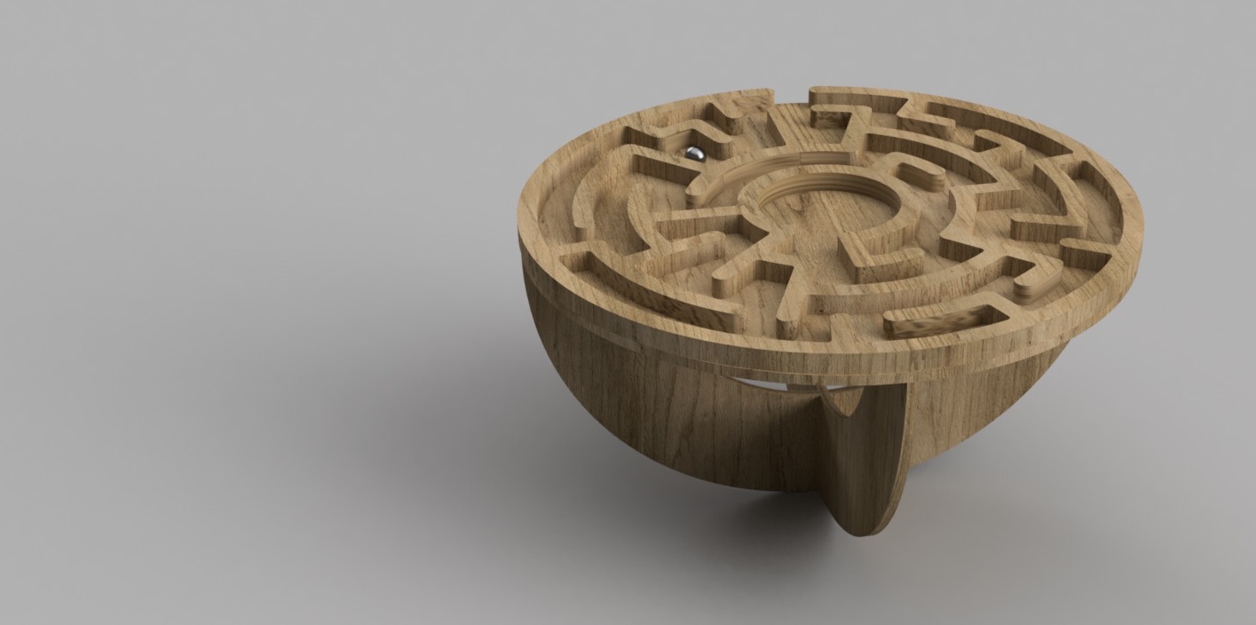
To visualize what it’d look like, I copied the files into sketches in Fusion 360 and did a fancy render.
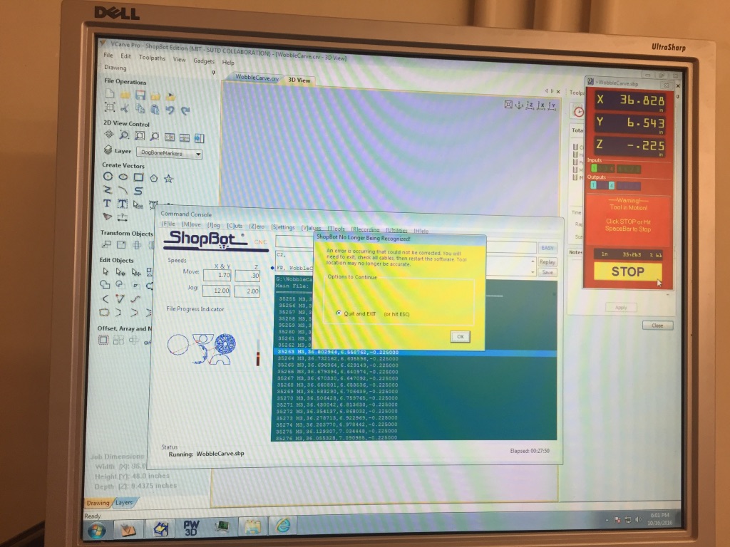
The first time I tried using the Shopbot to make the design, the tool didn’t go all the way through the material.
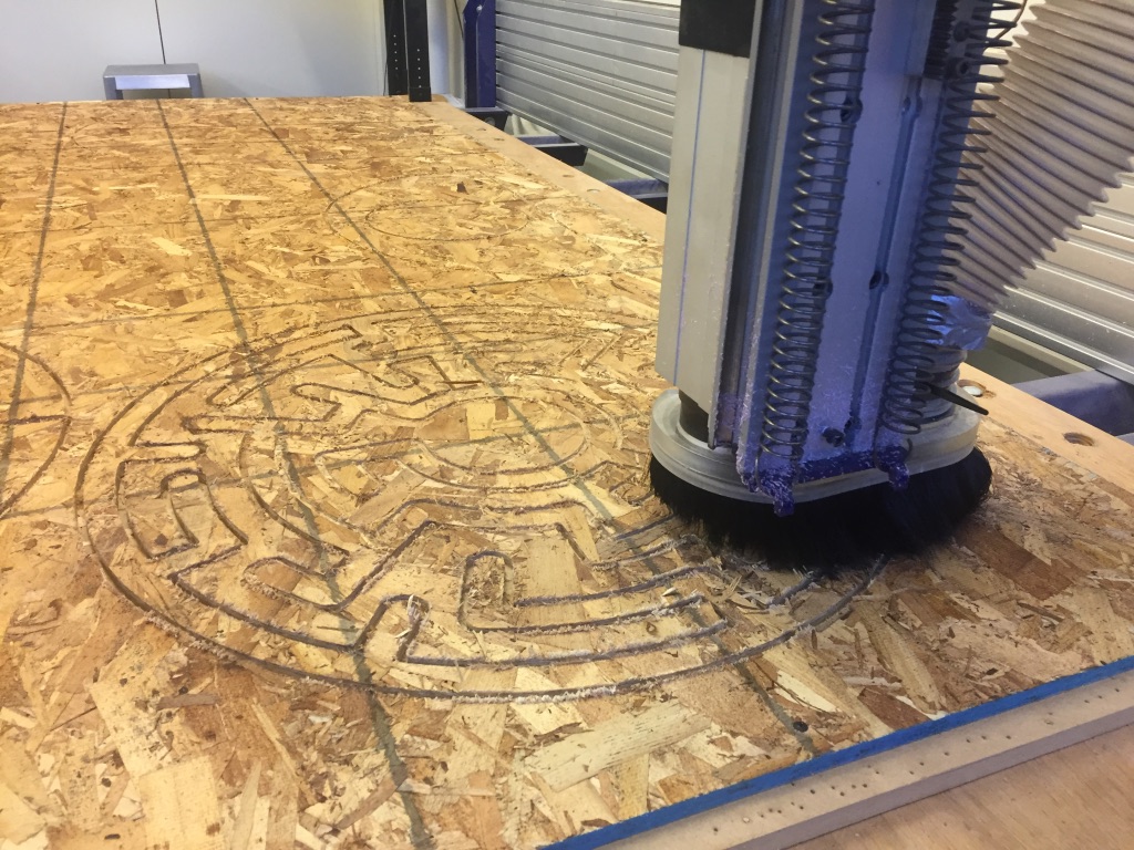
On top of that, it abruptly gave an error message and stopped working halfway through the cut.
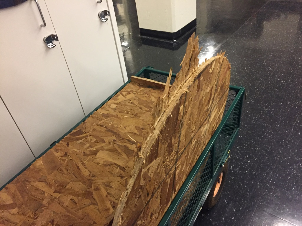
So when I tried to break things out, the edges ended up really gnarly. I didn’t even bother trying to do it with the maze that time.
The next time I tried to do it, it worked out. The original design called for two maze pieces which would be stacked onto each other to build a 1 inch wall, but the print job was taking a long time (40min+) and I decided to make do with only one.
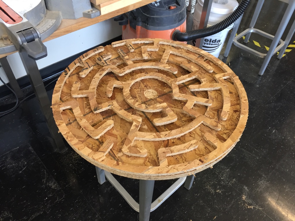
I attached the feet together and screwed it into the circular piece. Then I glued together the maze and the base.
And I colored the top with a sharpie marker (I didn’t have any paint!)
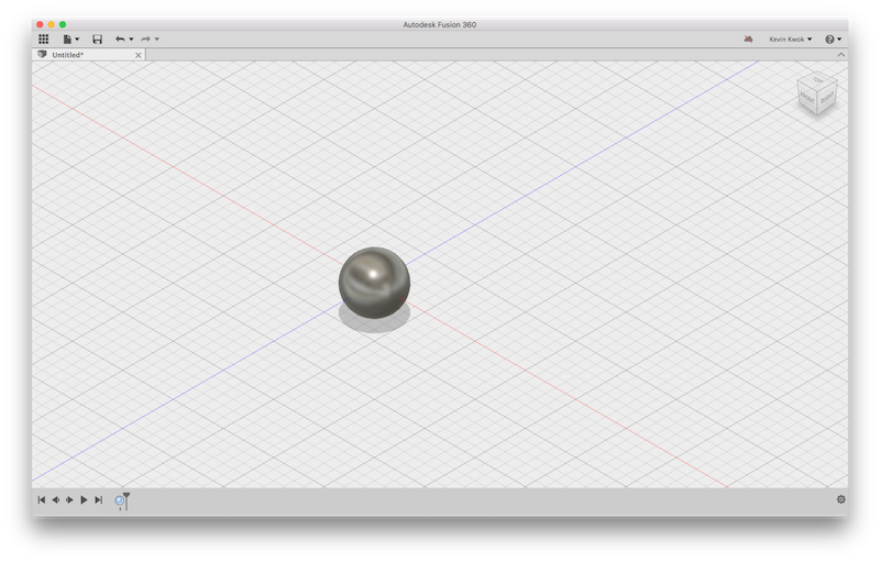
To top it off, I made a 1-inch ball which was 3D printed on the 3DWOX.
Week 4
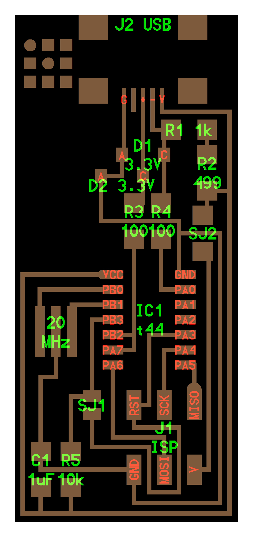
Circuit Design
This week I decided to use Eagle, because I had a little (absolutely teensy) bit of experience using it for 6.115 about two years ago.
The default library is quite large, so the first thing I did was to install the fab.lbr stuff and disable all the other built-in libraries except for supply1.lbr which has the symbols for GND and Vcc.
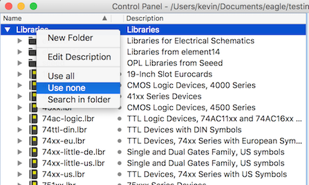
I turned off everything and then enabled the libraries that I wanted by clicking the little gray dot between the name and description.
After that I just put together the components by clicking on the little “Add” icon.
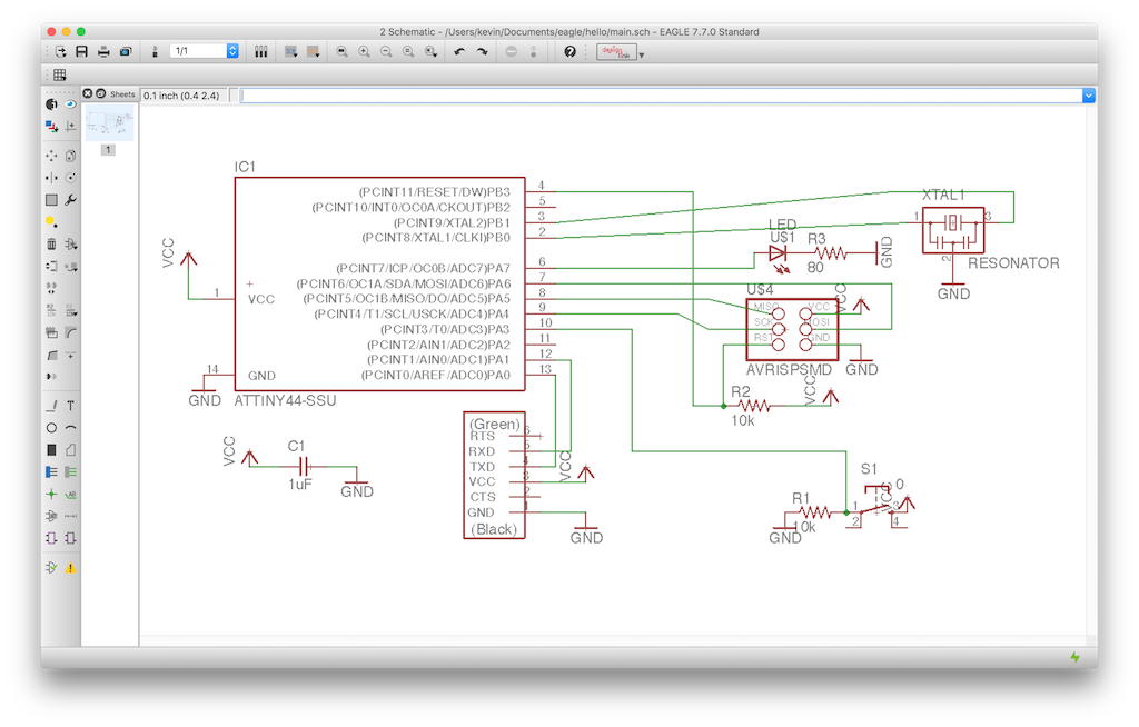
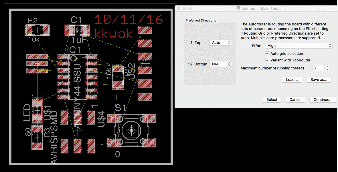
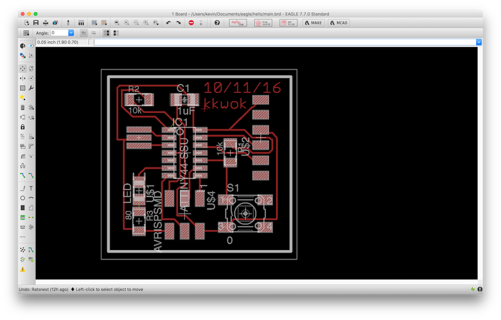
I switched over to the board view, and dragged the packages into what looked like a reasonable place. Then I used the Auto-Route
There’s an issue for recent versions (7.7.0) of Eagle for OS X on Retina devices where it exports things at twice the DPI without reporting it properly in the EXIF data. The fix is pretty simple, just double the DPI value from the “read png” block in the Fab modules interface. Check that the physical dimensions make sense as a sanity-check.
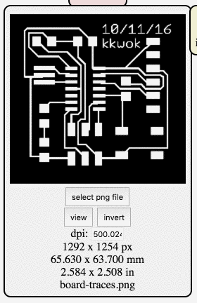
I learned this the hard way, and ended up wasting a couple copper boards where it seemed like my circuit didn’t fit. In part because there’s only a very narrow set of versions of Eagle which suffer from the problem (Anish did an experiment and it seemed dimensionally correct so I didn’t think to check mine).
My outline was a hairline white stroke where I wanted the mill to cut, which is apparently the wrong format. It ended up cutting twice, making a little frame and coming really close to consuming all the traces. In the end it seemed like it was okay.
Instead of a hairline where you want to cut, you want a solid white box around the area you would like to preserve.
Here’s a picture of a semi-populated version of the board (it lived a life rather brutish, nasty— but mostly cut short), which was the last photo I had taken of it before the accident.
While trying to program this board, I accidentally ripped off the FTDI headers and the accompanying traces.
Rather than trying to salvage the board (which wasn’t quite working right anyway), I made a new one. So here’s a photo of the shiny Mark II:
For reference, here’s a picture of a big white box, in case you didn’t know what to expect:


Week 3
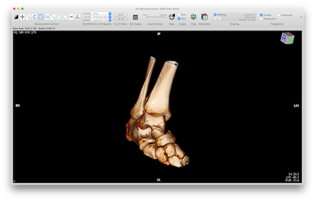
3D Printed CT Scan
This summer I had a lot of fun at a trampoline park
This much fun
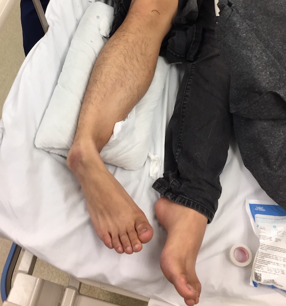
On the plus side, I left the hospital with this
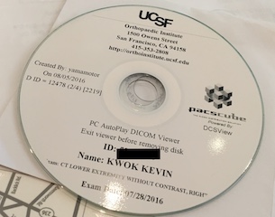
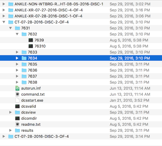
It turns out the CDs are filled with DICOM files
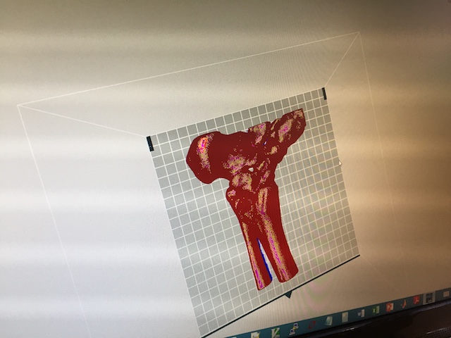
I found some software called OsiriX Lite which reads DICOM files
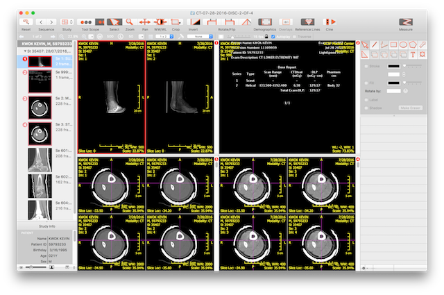
But it also lets you see things in 3D and even export to STL.
But the mesh is kinda messy, so I used the Auto Repair in the free Netfabb Basic
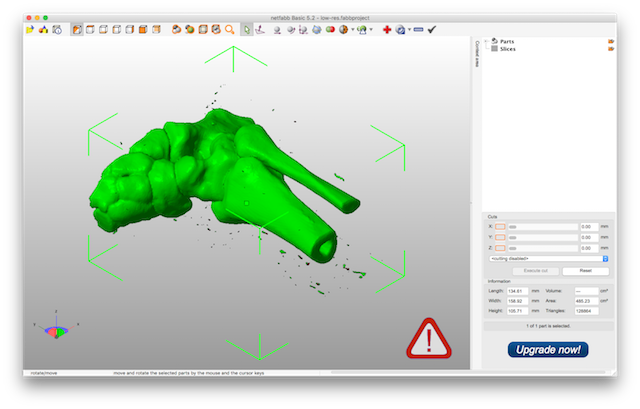
It worked well for fixing the geometry, but it crashed really often.
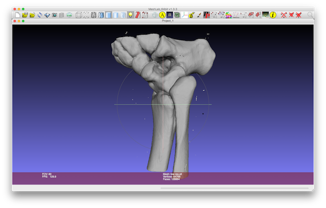
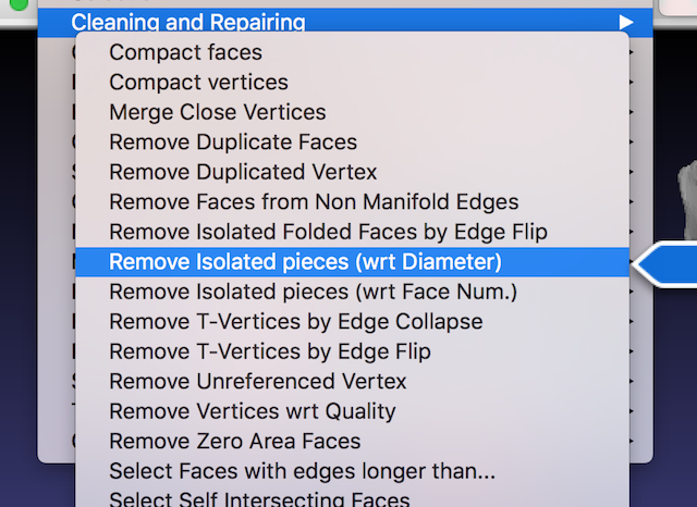
For the next level of processing, I used Meshlab
I removed the small bits with the “Remove Isolated Features (wrt Diameter)” transform.
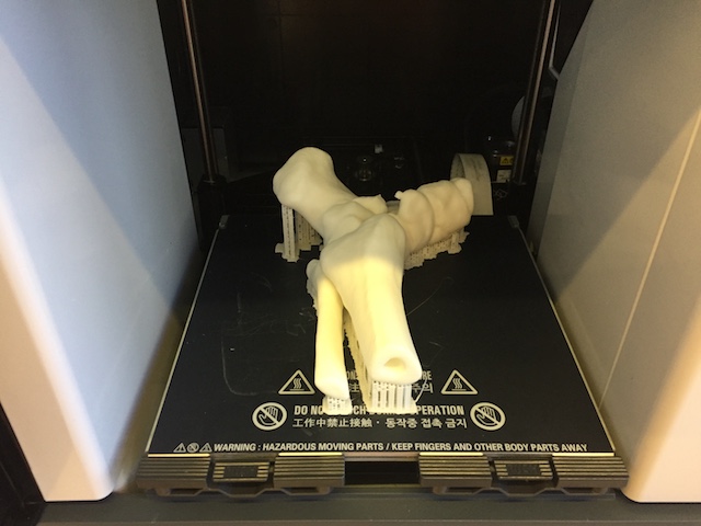
At this point it seemed printable, so I imported it into the Sindoh 3DWOX software.
I started the print job, which ended up taking over 12 hours.
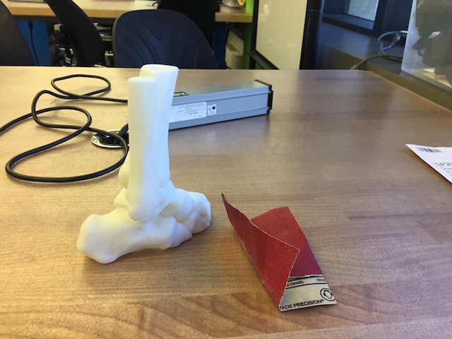
I removed it from the printer and sanded off the remains of the supports.
Week 2
Electronics Production
I fabricated Neil’s 3-Pin FabISP, but I had a lot of trouble programming it and wanted to make sure that it could work by programming a programmer. Also we don’t get our own miniUSB cables, so the key seems like it’d be useful.

So to test whether my programmed programmer could program programmers, I decided to make Andy’s FabISPKey.
NOTES

Week 1
Press Fit Mesh Kit
There’s some existing software like Autodesk’s 123D Make for converting arbitrary meshes into a form suitable for construction with a laser cutter, but essentially it just slices the mesh into pieces that you can stack together to create the shape.
That’s a good approach when you’re modeling some sophisticated shape, like a T-Rex and want to build something that looks like it.
But if you have something simple like a box or pyramid, you don’t want your design sliced up. Partially because it’s a big waste of cardboard, but also aesthetically because one face which really deserves to be a flat sheet of cardboard is now represented by the edges of a dozen sheets.
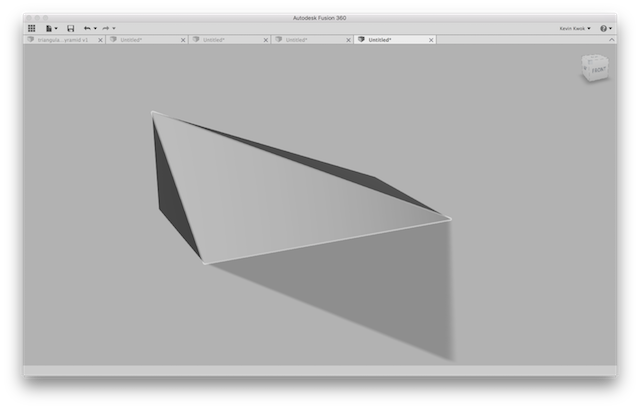
Lets start off with a little design made in Fusion 360.
There’s a neat piece of software called numpy-stl which lets us import STLs.
import numpy
from stl import mesh

# pyr = mesh.Mesh.from_file('triangular-prism.stl')
# pyr = mesh.Mesh.from_file('box.stl')
# pyr = mesh.Mesh.from_file('funktrap.stl')
pyr = mesh.Mesh.from_file('doorstop.stl')
Trying Angles
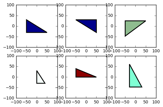
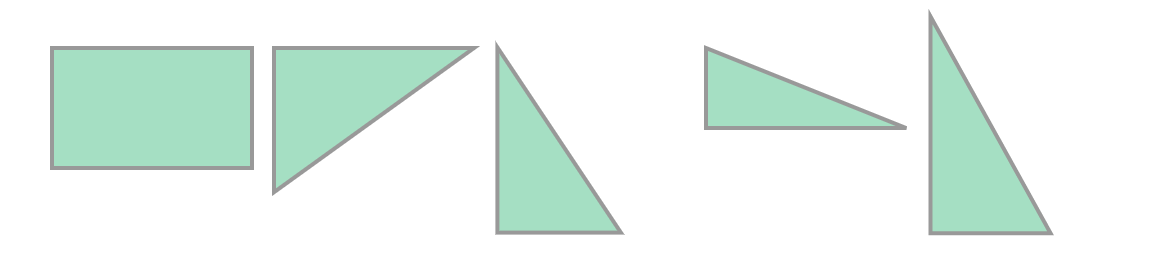
An STL file is a mesh of triangles. We want to work with a representation which consists of flat polygons.
The triangles are colored by their normal— so coplanar triangles end up displayed with the same color.
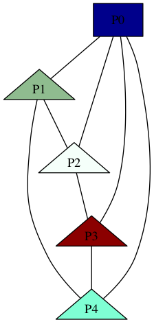
And we can look at how these triangles are attached to each other by visualizing it graphically— as in literally sticking them in a graph.

Off to Polygonia
To go from the representation of triangles into a representation of flat polygonal faces, we treat the mesh as an undirected graph where the vertices are triangles and the edges are literally the edges connecting the triangles. We run connected components with the additional restraint that components need to have the same normal.
For this we’re using Python’s Shapely library. It’s actually pretty overkill to use this complex geometry library just to trivially convert a set of points into a SVG path, but whatever.
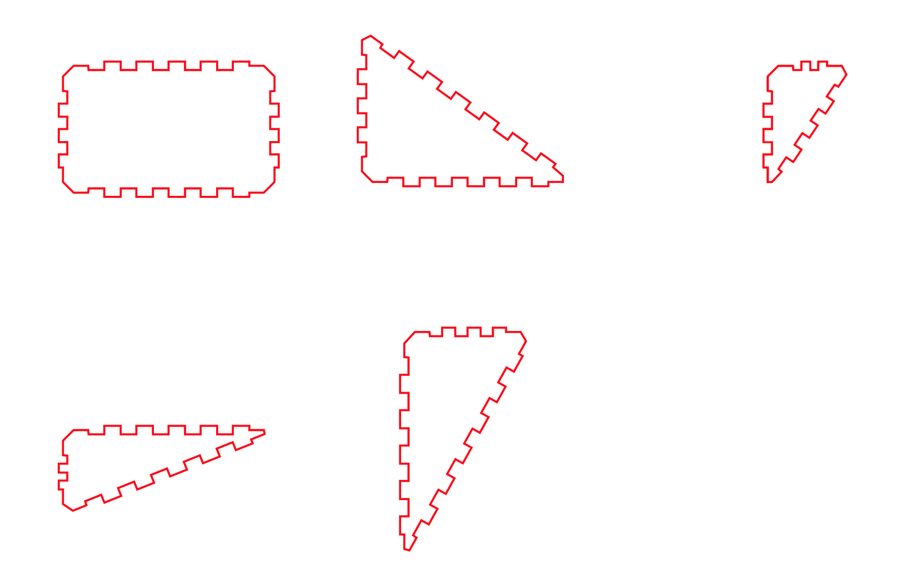
Kerfuffles
The last bit is to just draw out the polygons but to substitute the straight edges with little press fit pieces.
Week -1
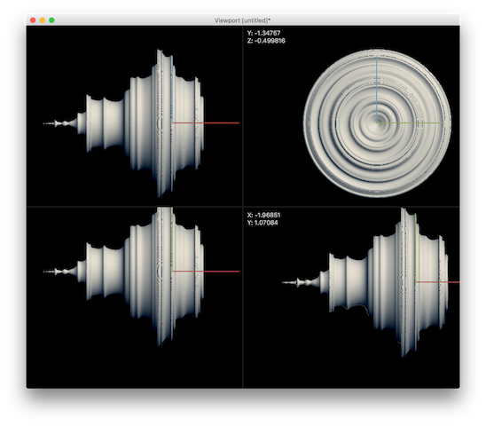
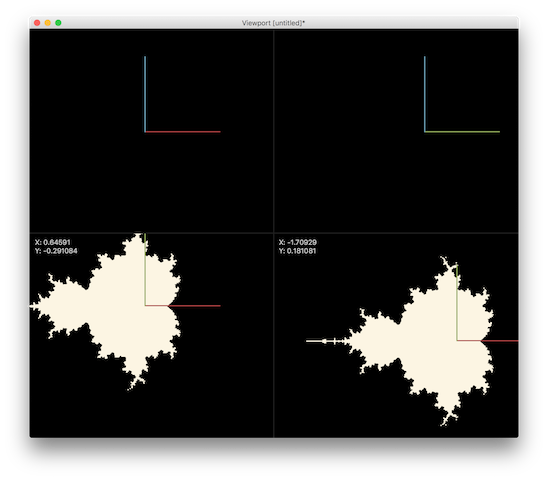
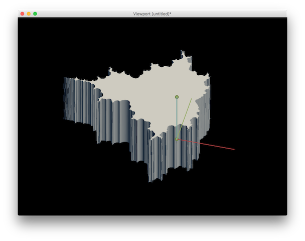
Modeling the Mandelbrot Set with Antimony
TODO: write words about how Antimony uses a function representation
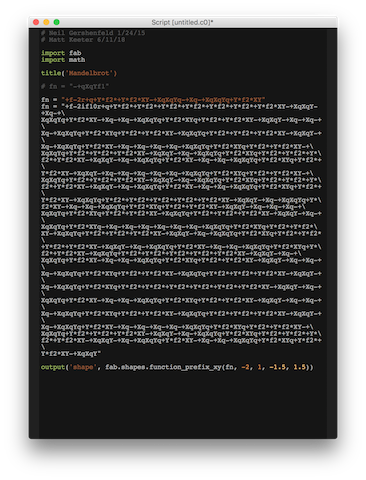
(* The f-rep syntax accepts four distinct types of atoms.X,Y,and Z \
are replaced
by position in the world\[CloseCurlyQuote]s coordinate system at any \
given evaluation point. *)
Antimony[x] := "X"
Antimony[y] := "Y"
Antimony[z] := "Z"

(* Table A.1:Unary F-rep functions (pg. 93) *)

Antimony[Sin[x_]] := "s" <> Antimony[x]
Antimony[Cos[x_]] := "c" <> Antimony[x]
Antimony[Tan[x_]] := "t" <> Antimony[x]
Antimony[ArcSin[x_]] := "S" <> Antimony[x]
Antimony[ArcCos[x_]] := "C" <> Antimony[x]
Antimony[ArcTan[x_]] := "T" <> Antimony[x]
Antimony[Abs[x_]] := "b" <> Antimony[x]
Antimony[Power[x_, 2]] := "q"  <> Antimony[x]
Antimony[Sqrt[x_]] := "r" <> Antimony[x]
Antimony[-x_] := "n" <> Antimony[x]

(* Floating point constants are preceded by f, followed by the value \
(e.g.f3.14159 or f6.023e23). *)

Antimony[x_Real] := "f" <> ToString[x]
Antimony[x_Integer] := "f" <> ToString[x]

(*Table A.2:Binary F-rep functions*)

Antimony[Times[a_, b__]] := "*" <> Antimony[a] <> Antimony[Times[b]]
Antimony[Plus[a_, b__]] := "+" <> Antimony[a] <> Antimony[Plus[b]]
Antimony[Power[x_, y_]] := "p" <> Antimony[x] <> Antimony[y]
Antimony[Plus[a__, -b_]] := "-" <> Antimony[Plus[a]] <> Antimony[b]
Antimony[Times[a_, Power[b_, -1]]] := "/" <> Antimony[a] <> Antimony[b]
Antimony[Max[a_, b__]] := "a" <> Antimony[a] <> Antimony[Max[b]]
Antimony[Min[a_, b__]] := "i" <> Antimony[a] <> Antimony[Min[b]]


Antimony[Min[10,
   ComplexExpand[Abs[Nest[(#^2 + x + I y) &, x + I y, 9]]]] - 2]