Week 2: Electronics Production
FabISP: The Programmer that Programs a Programmer
Sept 28, 2016
Assignment
Make an in-circuit programmer by milling a PCB and soldering components on the board. Test the board by programming it.
Tools used this week: SRM-20 milling machine, Soldering
Background
The goal of this week was to fabricate FabISP, which uses the Atmel ATTiny45 microcontroller to program other programmers. The workflow is to get the board layout as a bitmap, print it on a copper board with a PCB router and then solder components on the board. At the end, if everythign goes well, we should be able to program the board.
PCB Milling
A PCB router basically works like a printer: you give it a layout of the pad and the machine carves out copper on the board to create paths accordingly. We used Neil's fabmodule to interact with the tool. I used the hello.ISP.44.cad layout to make my board.
To setup the board, I cleaned the sacrifical board and my copper board with Isoproponal. Using double-sided tape, I fixed the copper board on the machine, making sure that the board is flat on all sides. I first wanted to print the traces, so I loaded the png file containing the layout and set PCB defaults to mill traces 1/64 and switched the mill head to a 1/64 head. By hitting calculate, the module takes the FFT of the png file and does some processing to calculate traces. The user can visually see the tool path by clicking view. The view option is helpful in determining where tool starts printing and setting the origin accordingly. I set the x and y value of the origin visually by incrementing the values until it was near to the corner of the board. Setting the z value was more challenging. I set the z value slightly above the board, unscrewed the tip, let it touch the board and tightened it again. It is crucial to make sure that the tip is not pressing too hard on the board or not touching it at all. Lastly, I set the jog value 2 mm higher than origin's z value. At this point, the job is ready to be sent to the machine.
There were a couple of difficulties that our group met when printing traces. The first time, we realized that the bottom half traces were narrower than the upper half. This was because the corners of the sacrifical board are not supported by the fixture underneath it, and the board moved up and down as the milling head put pressure on it.
Another difficulty was setting finding the right x and y origin to leave enough space for all edges of the board. As you can see in the next picture, the first time I tried printing, there was no space for the upper edge
Laslty, we didn't understand the difference between the jog value and the z origin at first. Since our jog value was not large enough, the tool left a path wherever it tried to jump from to the next point.
To cut the outline of the board, I used the file called interior.png, set PCB defaults to mill outline 1/32 and switched the mill head to 1/32.
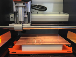
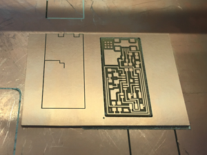
Here is the final result of milling:
Soldering
I'd already done soldering before, so I was fairly skilled at soldering. However, the most difficult part was to contorl how much solder I put on each pad. I tend to put a huge blub which makes it diffciult to solder the first pin of the surface-mount components. I got better with practice, but since I desolder the exessive solder everytime, it took me a bit long.
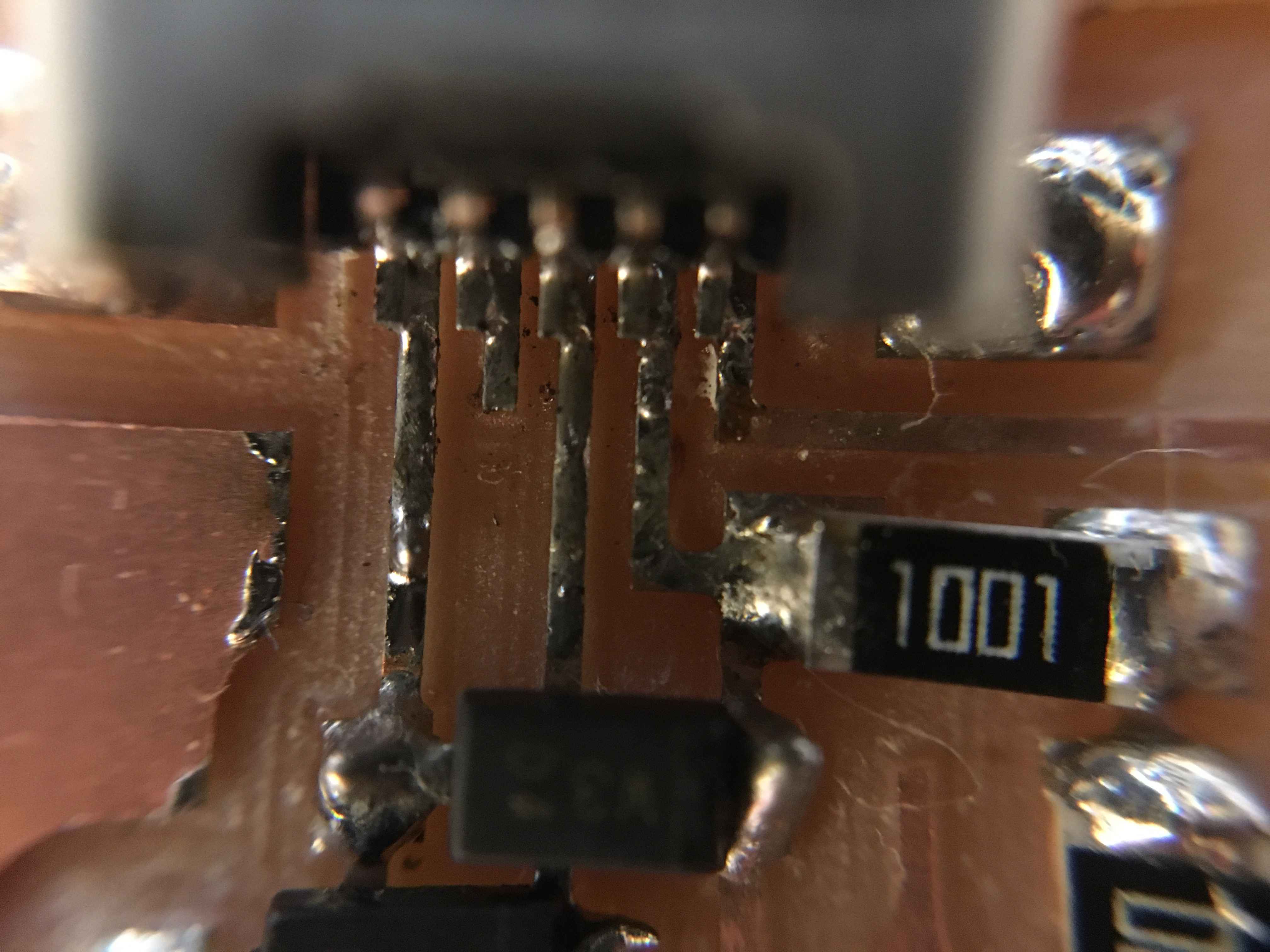
Here is a microscopic veiw of the finished board:

Programming FabISP
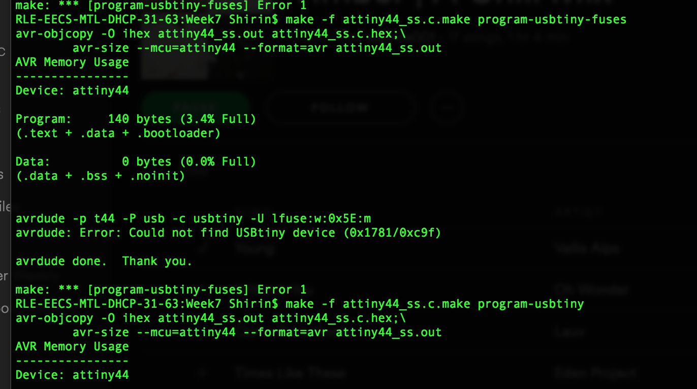
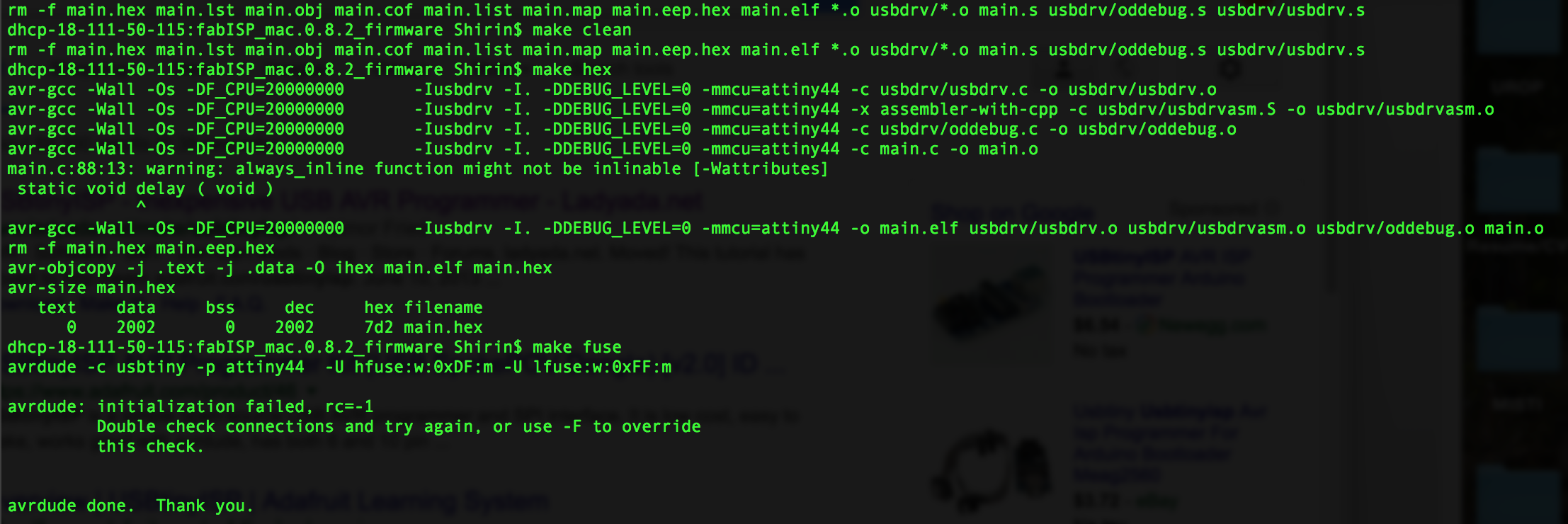
This week, I was not able to successfully comile the firmware. I successfully powered up the board with a usb cable and used the header to connect the board to a USBtiny AVR programmer. My 'make clean' commaned worked successfully, but I got the following errors for 'make hex and make fuse':
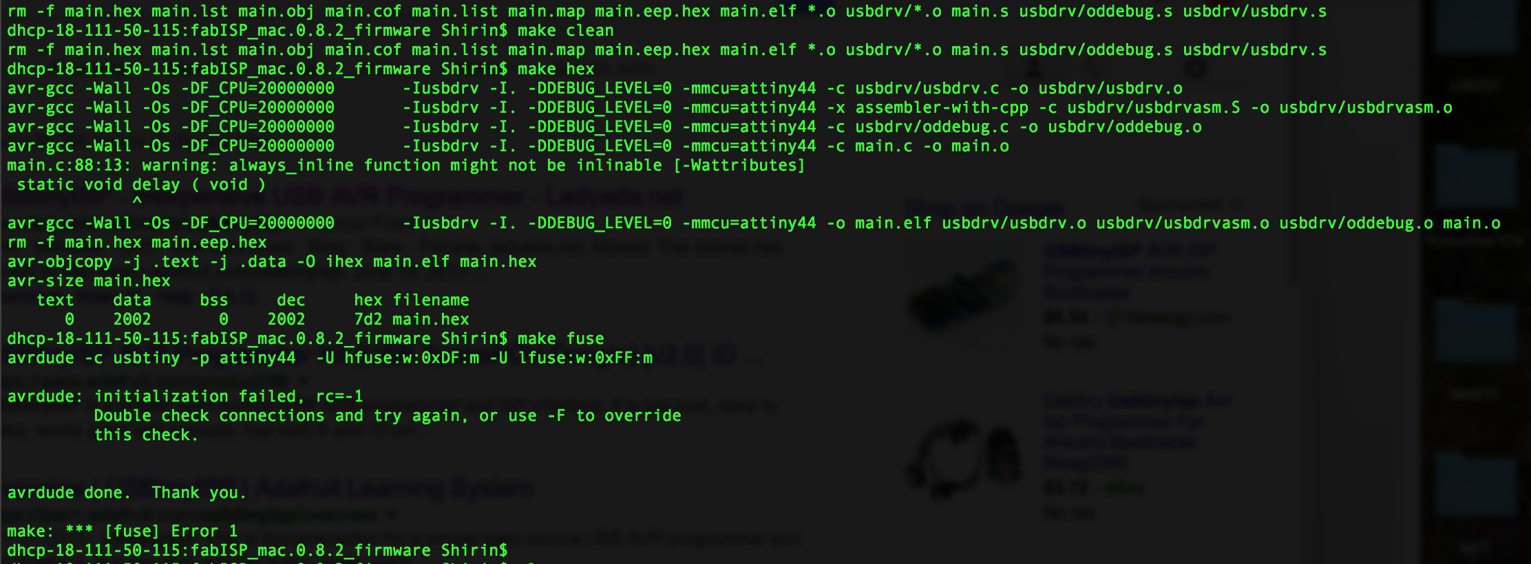
I visually inspected my board and didn't find any shorts or opens. I will do a more thorough examination in the coming weeks.
UPDATE: It was an easy fix: I hadn't soldered the actual pins of the microusb header - I'd only soldered the mechanical pins. I was able to program the board now!