Week 8: Input Devices
Measuring with the Step Response
Nov 9, 2016
Assignment
Measure something: add a sensor to a microcontroller board that you have designed and read it.
The Step Response

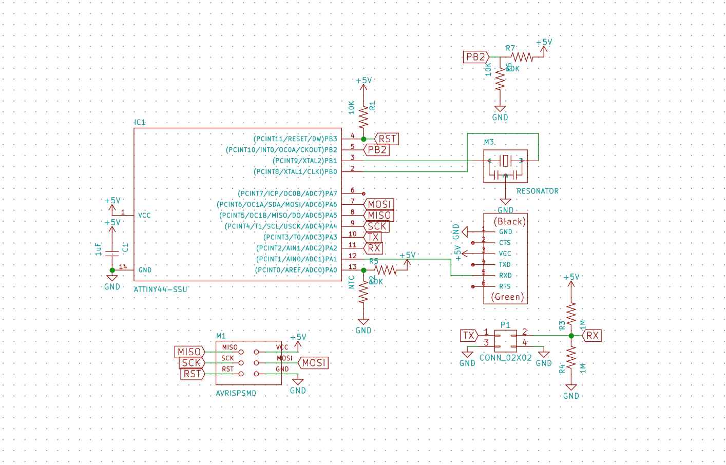
Since I don't need to use a sensor with my current final project, I decided to make the step response board designed by Neil, which is applicable to many measurements. It was hard to understand how the programming works, so I decided to begin with just making the exact board and playing with it. Later I will add the step response with maybe another sensor to my own echo hello world.
The board uses one of the I/O pins repeatedly transmit a step signal and another I/O pin as an ADC to receive the response of the system to the step signal. You can observe the change in the electric field between the RX/TX pins and measure many things such as proximity, humidity, angular position, etc.
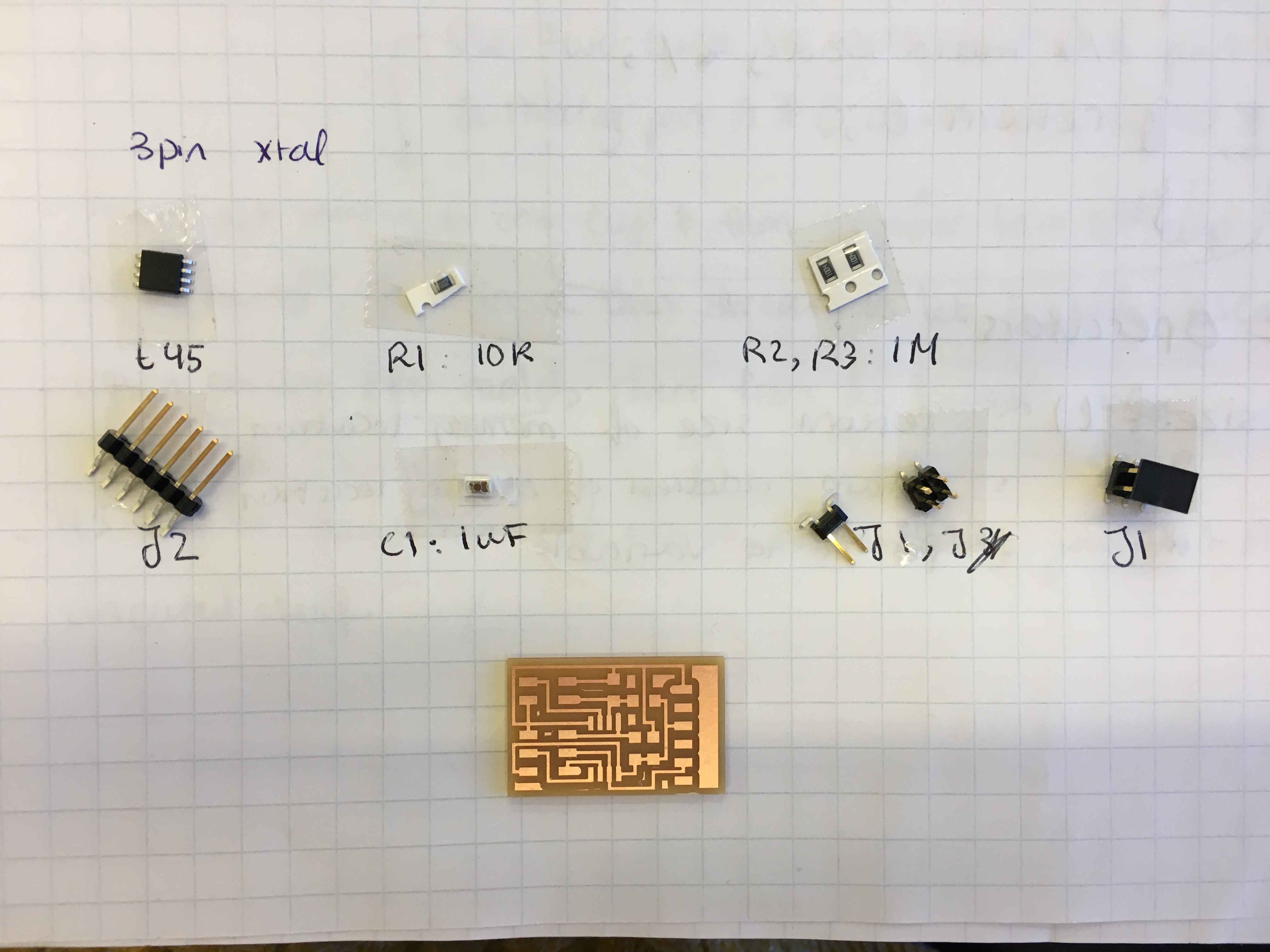
Milling and stuffing the board was pretty straightforward, as I'd done it a few times. But as expcted, the first time I connected the board to my computer, I couldn't program it. Almost every other time , when I connected the usbtiny programmer and my board to the computer, I got a warning saying usb device is disconnected because it's using too much power. When the device wasn't disconnected, initialization failed.
A command line that I found useful in this debugging process was ioreg -p IOUSB which lists all the usb devices connected to the computer plus a lot of details about them, which I didn't understand. But it was helpful to see whether it's the programmer that is disconnected or the attiny board.
Usually this means one of the connections is shorted, so I tested all the connections with a multimeter and couldn't find any shorts. Next thing was to make sure that all ISP connections between the ISP header and the microcontroller are correct. With the multimeter, I found an open between SCK pins. I resoldered the pads and tried programming again. It worked!
I connected the TX and RX pins and to two copper sheets. I was unsure what to do with the ground connections, but I thought it would make sense to at least have them connected together so that the RX and TX signals both have the same reference. Then I used Neil's python interface to visualize the step response by running the following command in terminal:
python hello.txrx.45.py /dev/tty.usbserial-FT9KZ5G
If you just run python hello.txrx.45.py you'll be asked for the serial port device. Then you type /dev/tty.usbserial and hit tab to complete the rest.
Here is some cool demo of the sensor measuring ditance between the pads:
Hybrid Humidity and Temperature Sensor
Now it's time to move on to making a more complicated board. The step response can be used as a humidity sensor, so I though it would be cool to mix it with a temperature sensor on my echo hello-world board and have a custom made humidity and temperature sensor. I modified my board from the embedded programming week. I freed up pins by removing the button and the LED and instead using them as ADC pins for the step response and the temperature sensor. I made the schematics and the footprints but ran out of time to make the baord and program it.