
Week 12: Networking and Comms
Since my project has been reliant of multiple networked nodes from day one, I've already been making use of I2c for almost every electronics project this semester. This week was intended to be a time to tie the entire project together.
The major remaining board I had to make was the Radar monitoring board. I finally got around to routing it this week and it was my plan to stuff it and get the entire system commmunicating over the I2c interface I've been building all semester.
I used the special circuit milling machine at work to make a double sided board and simplify making such a large board. I also played around with electroless through-hole plating for making vias. This process is quite useful for plating lots of small vias simultaneously and is a alternative to rivets. However, this process is not as simple as using the rivets and requires special safety precautions; it requires a chemical fume hood, corrosion resistant equipment, and experience handling chemicals properly. In the future, I'll probably only use through-hole plating in very specific instances and use rivets for most simple boards.
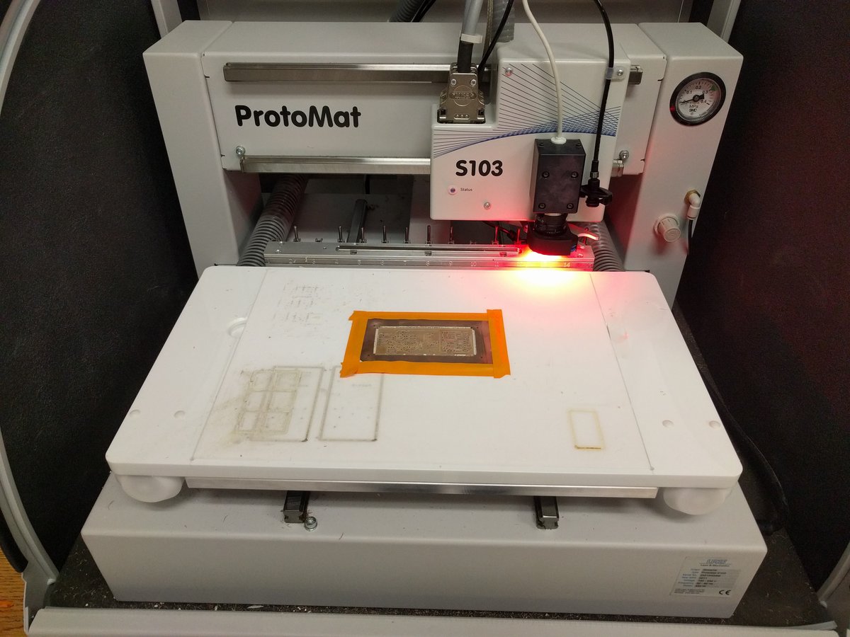 The big PCB milling machine at work makes quick work of double sided PCBs thanks to automatic tool change and optical registration
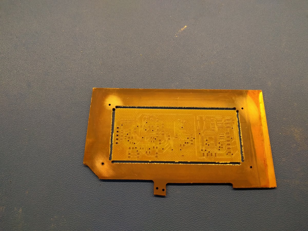 The milled board. The discoloration is the successful result of the through-hole plating process.
Meanwhile, the Op-amps I was waiting on from DigiKey which were required to complete the board decided they didn't want to cooperate with my schedule.
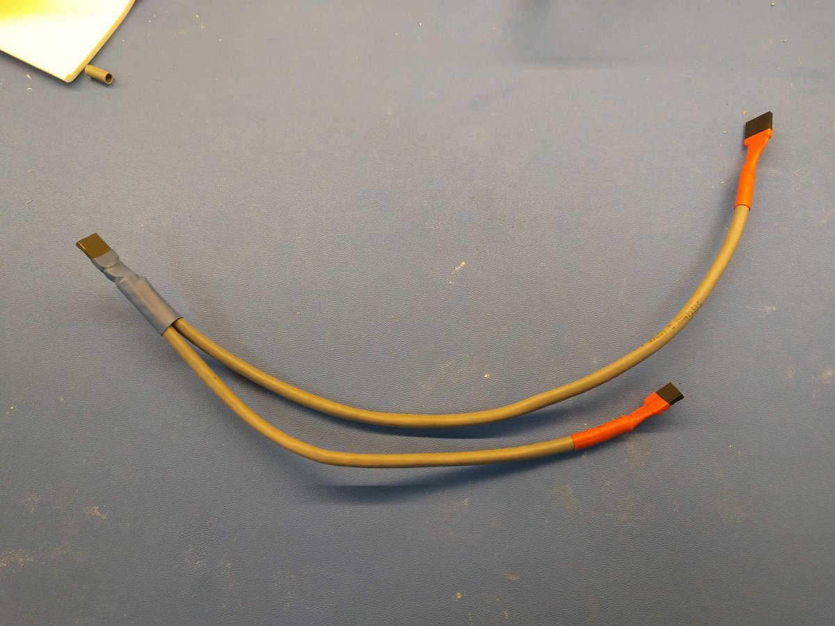
Instead I decided to put off finishing the main board until later this week and get some of the other networking related functionality working. One of these tasks was getting the cabling harness which will connect all the boards together made.
For cabling, I decided to use CAT-5e (commonly used for Ethernet) UTP (Unshield Twisted Pair) cable. It's 24 AWG so it can carry more current than the inexpensive ribbon cable. Additionally, The cable is quite cheap and abundant and has 8 conductors which means that there are enough strands to carry the I2c signal lines, VCC, and independent ground connections to avoid ground loops.
I'm interested in trying the vinyl cutter method to make my final harness but I suspect this may be a more weather resistant and durable solution.
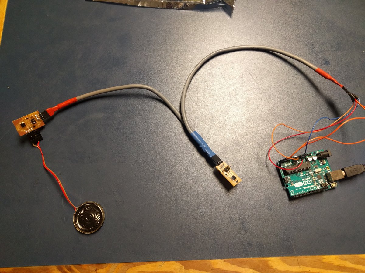
After making the harness, I connected the two boards I had from previous weeks. Then I wrote a quick Arduino program (Adapted from an Arduino example) and used an Arduino Uno R3 in lieu of my final board. Although not ideal, this setup allowed me to test the functionality of the harness and ensure that both devices worked on the I2c network simultaneously.
        #include <Wire.h>

        void setup() {
          Wire.begin();        // join i2c bus (address optional for master)
          Serial.begin(9600);  // start serial for output
        }

        void loop() {
          Wire.requestFrom(16, 1);    // request byte from slave device #16
          Serial.println("Speed is:")

          while (Wire.available()) { // slave may send less than requested
            char c = Wire.read(); // receive a byte as character
            Serial.print(c);         // print the character
          }

          delay(300);

          Wire.requestFrom(40, 1);    // request byte from speaker (this actually plays the tone)
          Serial.println("Playing speaker")
          delay(300);
        }
I initally started this semester not knowing about the multiple drop serial implementation. I still opted to use I2c for the project as the semester went on due to its provision for collision detection allowing multiple masters. I've yet to use this functionality yet on this project so I may think about simplifying my interface.