
I have decided to check out Eagle PCB Design Software. The download and installation process is pretty straight forward. I have used Altium before on a PC, but that was quite a while ago and I cannot really remember much. So here goes…
I am going to recreate the echo hello world-board with some added components. I feel like this board will be extremely helpful for my final project as I will need to utilize some analog sensors and be able to read in and track the measurements. There is more information on the sensors on my final project page.
My final project is linked here
The components I am going to add are:
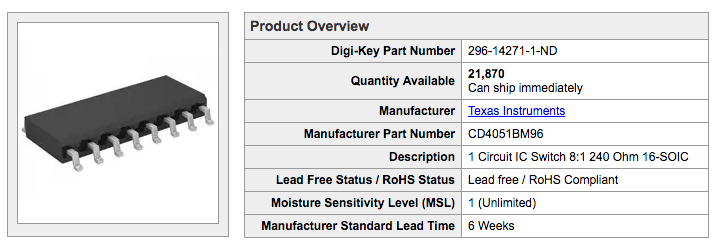
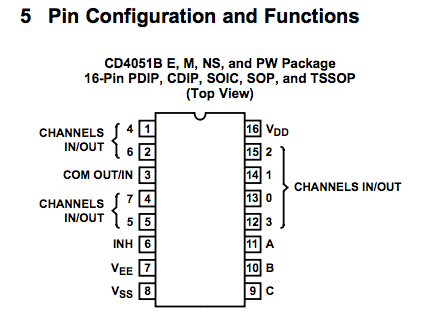
An analog multiplexer/demultiplexer (CD4051B) - This will give me freedom to receive information from eight different sensors using just four of the microcontroller pins. 3 pins are needed to differentiate between which sensor information is read and 1 pin to write to the COM IN/OUT pin of the mux (multiplexer)
An LED – I am going to use this to check if my mux/demux pins are responding. I can connect the LED to each of the mux/demux pins and write a program that will flash the LED.
Okay - I have been battling with eagle for some time here are some of the things I have learnt:
1) If you accidentally close the tool bar on the left of the screen go to Options -> User Interface and then check the corresponding box.
2) In order to move components, make sure the move cursor is above the cross-hairs of the component.
3) To add ground or VCC use the supply1 library that comes with eagle – it has symbols for these.
4) In schematic view you must use the NETS tool to connect components NOT the wire tool. This is not intuitive but extremely important!!!
5) It is easier to use the default grid settings. The default grid lines are well spaced – this make connecting the wires to the pins a lot easier as the cursor locks to grid lines – if the lines are too close you may miss the pin and therefore despite looking like there is a connection when you go to the board view the components are not correctly connected.
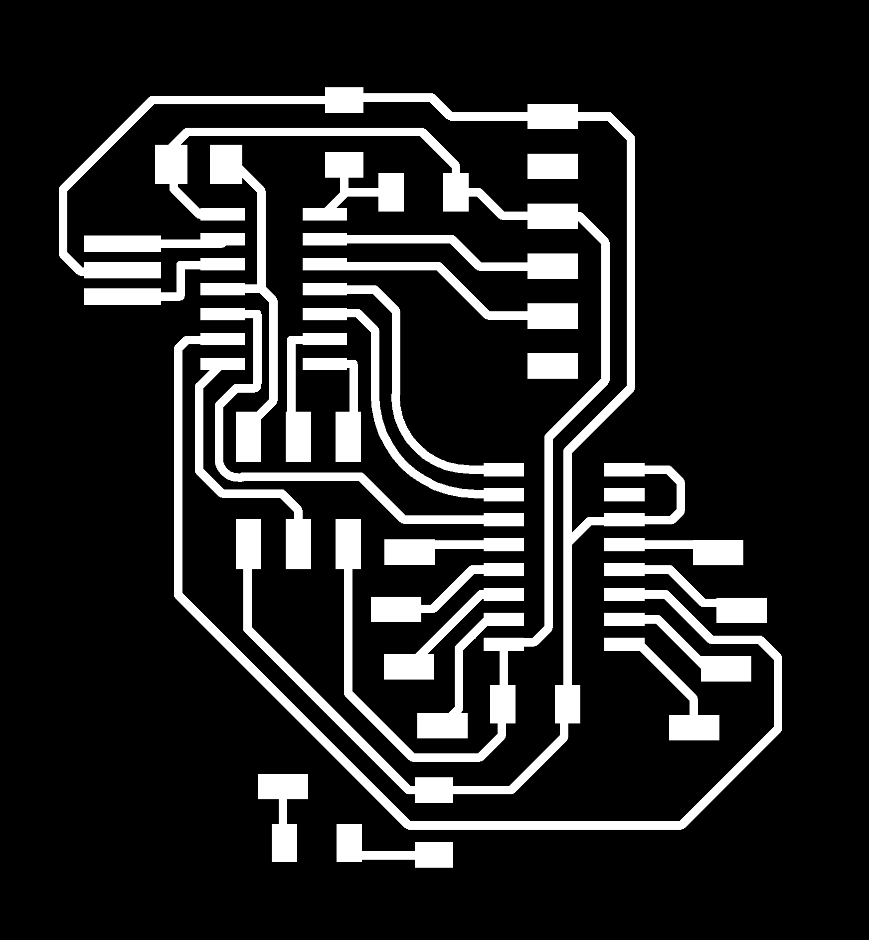
6) When saving as image to PNG first make sure that the only visible layer is TOP layer. You must also select the monochromatic checkbox in the save window.
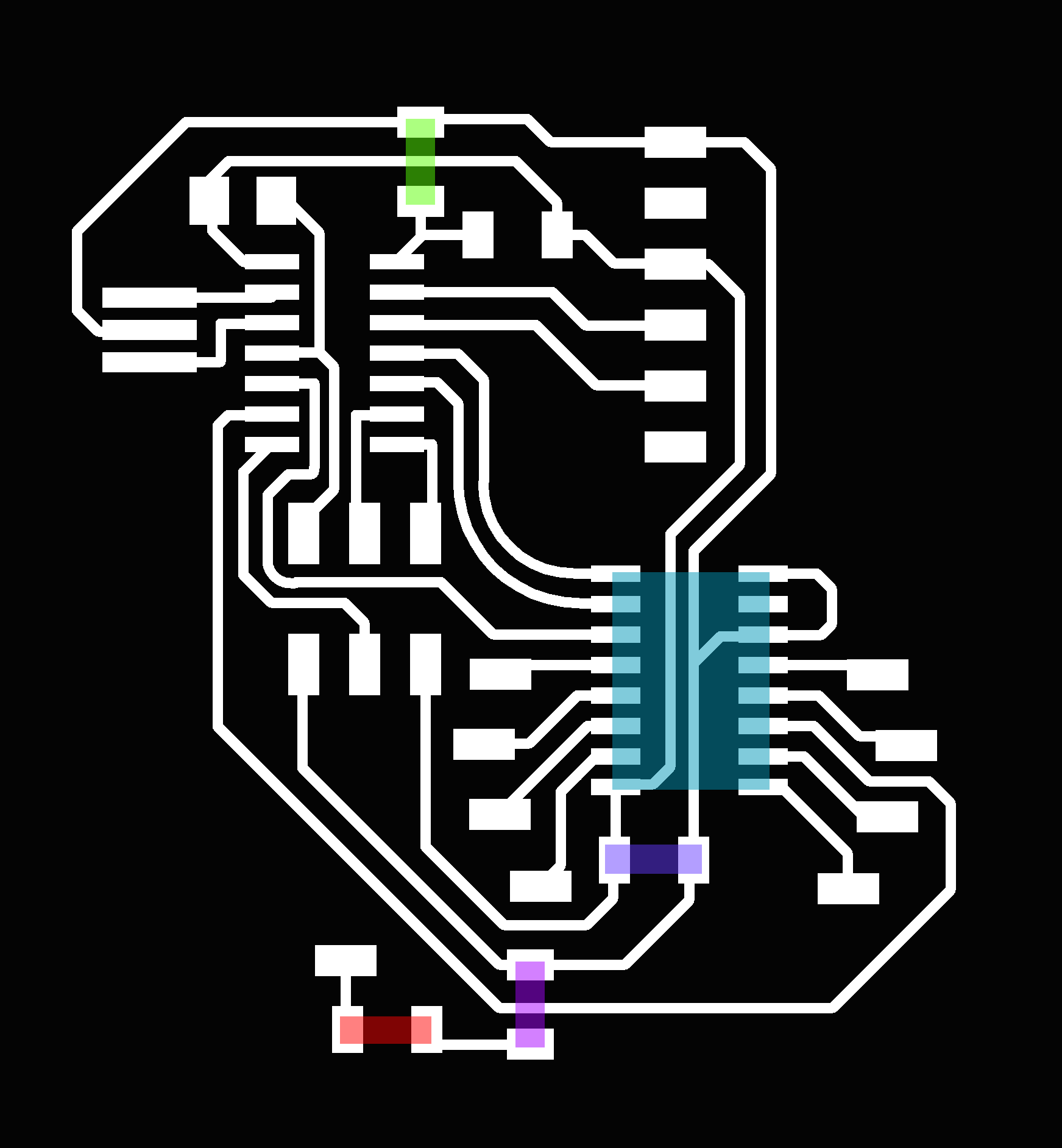
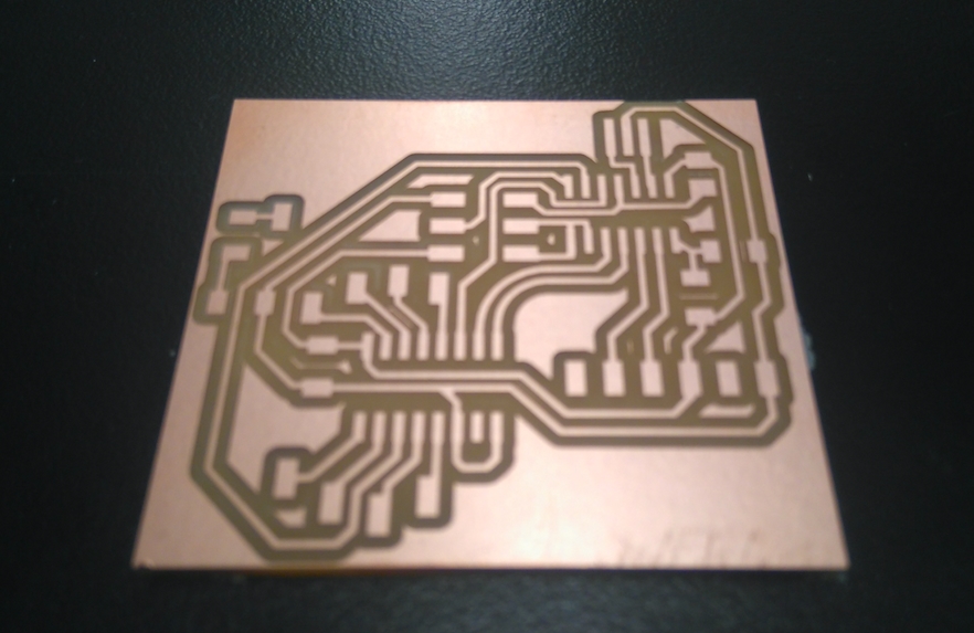
Here is my PCB design. The jade is the multiplexer. The green is a zero ohm resistor. The indego is a 0.1uF capacitor. The purple is a 1k resistor. The red is an LED.
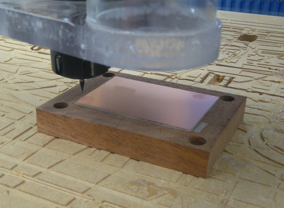
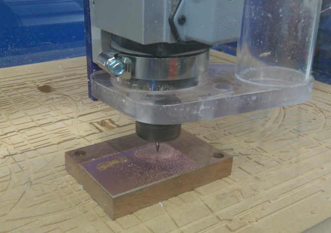
I used the Shopbot again (I used it to mill my programer as well). This time I had a much harder time. Here are some problems I ran into:
1) The wooden block stage was not level - ALWAYS make sure that there is no material shavings on the wooden block and use a razor to make the surface flat.
2) The mill head was not low enough to cut all the way through the copper. I lowered the z-origin by 0.002mm and then started again.
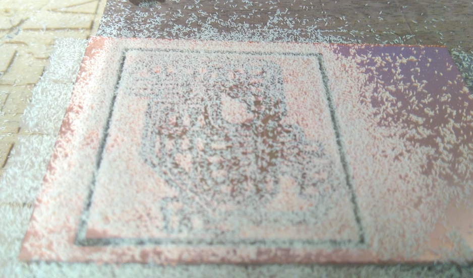
Oh my goodness!! It milled through the plastic but not the tape!!!.
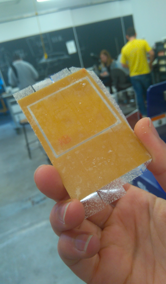
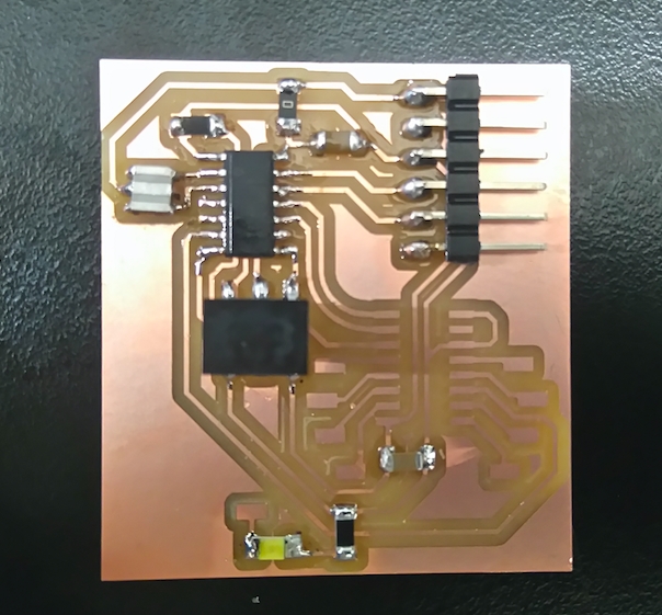
I got completely absorbed in soldering my board again and forgot to take pictures, anyway here is the end product. The gap is for the multiplexer - I have ordered it from digikey and it will be arriving soon.
.