AVR Output
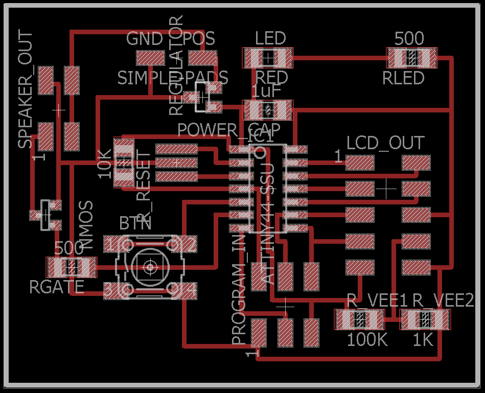
I have decided to change my final project because I don't think I'll have enough time to do all of the woodworking to get a full table done before the end of class. Therefore, I am going to make an alarm keypad. I want it to be able to sense motion near the pad and to allow for button input and LCD output to control it and a speaker to sound the alarm. If I have time I'd love to also network it to other devices and be able to connect the keypad to door and window sensors etc. But for now I want to work on my basic outputs. Therefore, I took Neil's basic LCD and speaker boards and combined them into one board and added a button so that I can change the LCD text with the button and begin coding up something that responds to button pushes. Therefore going back to eagle, which I find makes total sense at this point, I quickly drew the schematic, routed the traces, and exported the traces, and the outline for milling. Then it was time to mill it on the Roland mill which at this point is my good friend (as long as it cuts all the way through on the darn outline pass this time).


Milling went great! Cut through no problems yay! I plugged it in with a 9volt battery and the power light went on no problem! I tested the board by loading Neil's sample code for the LCD and for the speaker and they both worked great (note: make sure to change the ports on the default files and the speaker from Attiny45 to Attiny44). So everything at a high level was looking great! I also designed a cable extender board if you happen to solder onto the LCD too short of a cable (like I did at first). Here is the board file and schematic -- it is just the two 2x5 headers and a bunch of 0ohm resistors to connect all the right wires. I milled one out using Neils new Fab Modules 2.0 (for the first time). One note on that is that there is no more z0 but the thing that is where z0 would be is zJog and if that is zero it will scrape along the board's surface which is bad so don't change that! Anyway I didn't end up stuffing that board because I decided to go to town with the braid and desolder the short wire and resolder on a longer wire. One key cautionary note I figured out while testing Neil's demo code: DO NOT LEAVE THE BOARD POWERED ONLY BY THE PROGRAMMER FOR A LONG TIME OR THE REGULATOR WILL GO NUTS!. This must have been my problem in week 9 and why it got so hot that it hurt my board that week. This week I caught it in time and stopped it!
Then it was on to writing some C for my own custom code. Once agian I tried really hard to move everything into a header file and once again it was a disaster. I don't know why but moving Neil's helper functions to a header file causes them to not work even when using the correct types etc. They simply made the LCD a black bar. Weird. Anyway after wresting with that for a couple of hours and giving up (I will succeed and make pretty code one day), I decided to move on with one file. From there I was trying to write a function to take in a uint16_t and output a character string of that number to display on the screen. I will need to do this dynamically as users input their code into the alarm system for my final project. This was much harder than expected as sprintf seemed to not want to work. Instead brainstorming with some classmates we came up with a recursive algorithm to strip off one digit at a time from a number and then hard code the string for each digit and then print each digit with a switch statement. It works! I can count as high as I want with my debounced button input from week9! Next I wanted it to sound the alarm at odd numbers for testing. I can get the speaker to do stuff at odd counts but since I can't use the delays as Neil had them with the rest of the debounce and LCD stuff I couldn't figure out how to get the alarm working on the same board too. But still great success with them independently as by running Neil's example for the speaker and tweaking some values I can get the annoying 520 hertz alarm noise! This is further proof for me that the multiboard networked approach is probably a great approach for the final project as I can break each component off into seperate boards where I know the smaller chunks of code work!
Here is my final code and the makefile as well. One fun note on the makefile I changed it so all you have to run is "make program-usbtiny" with the c code and Makefile in the same folder and it will compile the code and then program with usbtiny. Also if you just run "make" it will compile the hex. No "-f" flags needed! However, if you have avrdude working on your path (my windows path is giving me a hard time) you will have to change the avrdude variable to just be the word avrdude instead of the path I have and then it will work. If you are also having path issues just update that variable to your path to your avrdude executable and it will work as well!
