Jaclyn Berry
w5: Electronics Design
Echo
A lot of learning happened this week. In my fever-ridden delirium, I made a big effort to learn how the electronics on this week's Echo board actually work. I'm pretty good at splicing together circuits that other people have made, but I don't have a strong foundation in basic electronics. This week was an opportunity to start fixing that.
So, I read A LOT of datasheets. I read a fairly large chunk of the ATTiny Datasheet and learned that the ATTiny is a pretty powerful microprocessor. It can do capacitive touch interfaces! I read about crystal oscillators and ceramic resonators. I briefly introduced myself to piezoelectronics—super fascinating. Mechanical stresses become electric charge?! So awesome. I also learned how to calculate the required resistance for an LED. But more on that later.
Step 1: Understanding the Electronics
The biggest hurdle I had to cross this week was pullup resistors. We went over this in class, but it took me some extra effort to actually understand how they work. Here's what I learned:
It all starts with floating values. A powered pin without any pullup resistor or ground connection can pick up noise signals from nearby equipment, etc. This can cause the pin to falsely read HIGH or LOW.

In order to bias the pin state to HIGH, you have to directly connect it to power (5V) and ground to complete the circuit.

The problem is, without a resistor between the pin and power, the pin acts kind of like a voltage divider which means the voltage at the pin is dependent on the length of wires to power and ground. For instance, the voltage at the pin might read 2.5V or 3V.

The microprocessor doesn't know how to interpret these in-between voltage values. There are a range of predefined voltages that the microprocessor understands as HIGH and LOW. The pin voltage needs to be within one of these ranges.

So if we stick a resistor between power and the pin while the switch is open, the pin will read HIGH.

But if we close the switch, the pin is much closer to ground (current will take the path of least resistance) and the pin will read LOW.

The second electronics thing I learned this week is how to calculate the necessary resistors for an LED. I used R = V/I. According to the LED datasheet, the fabshop LEDs usually operate at 1.8V (V) with 20mA (I). Plugging that into the equation we get (5-1.8)/(20x10^3) = 160 Ohm. There were no resistors near 160 Ohm in the lab, and I didn't want to place a bunch of 1206 on my board to get the exact resistance (too much space), so I selected a 200 ohm 0603 resistor from my personal stash. I know it's higher than the value I calculated, but I figured it was better to air on the safe side.
Designing + Making the Board
After I understood what was happening on the example Echo board, I drafted my own. I included a button and an LED. Originally I had my button directly controlling the LED, but Ali advised me that having a button assigned to its own pin would let me use the button and LED separately.
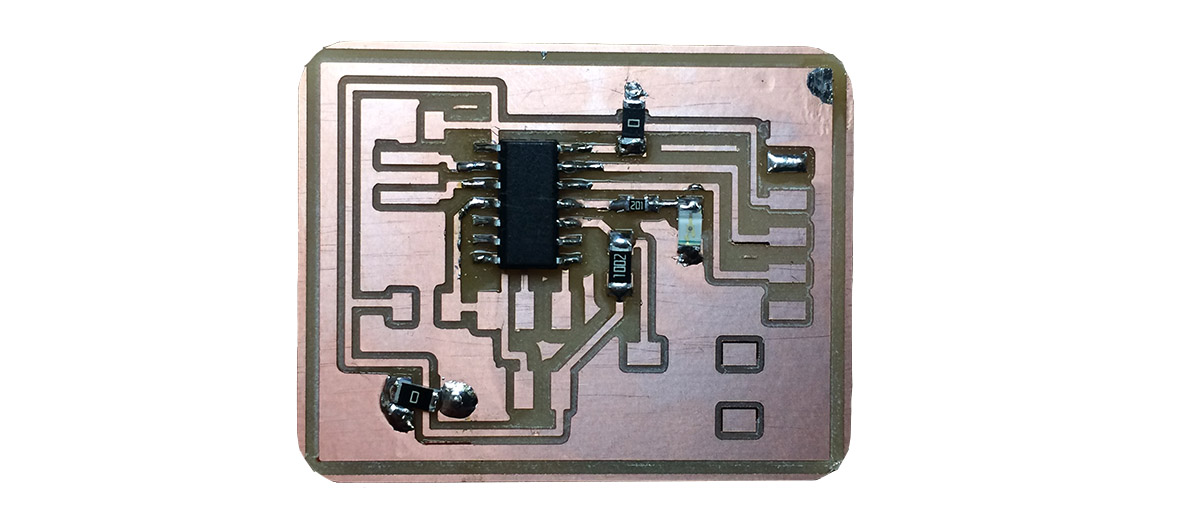
My first board design was ugly and did not mill well. I used several 0 ohm resistors to jump over traces to a giant ground pour. The pads connected to the ground pour did not cut out, which turned out to be a a nightmare for soldering.

I had a lot of problems soldering components to the ground pour. Calvin helped me at this point, but he also experienced difficulty. He turned up the iron to 800+ before the solder would melt onto the board. My guess is that the heat was dissipating through the ground pour, so the copper wasn't hot enough for the solder to flow. But more than that, without a well-defined pad, the solder was really difficult to control.

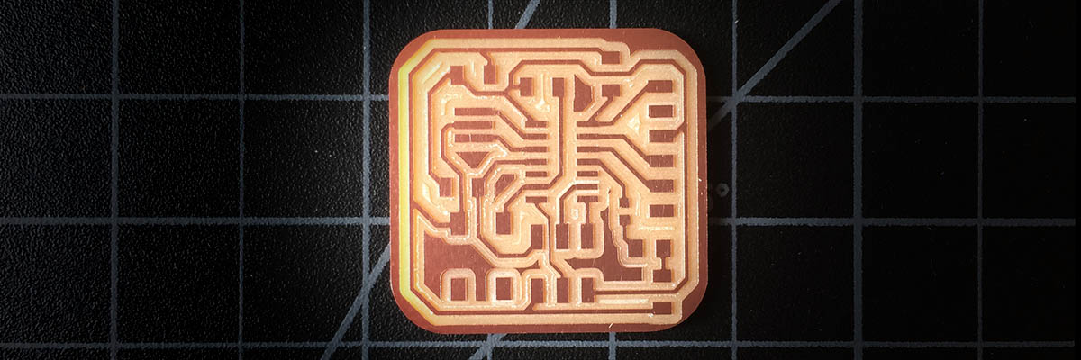
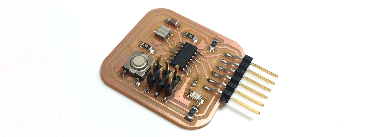
My second board came out much better. I switched IO pins for my button so that I could place it on the left side of the ATTiny. I also opted for a ground trace instead of a ground pour to avoid the problem from the previous board. I used the SRM-20 for the first time to mill this board.

Soldering for this board went very smoothly. I had to trim one of the metal fingers holding the cap on the button because it hung down over one of my other traces. I tested all the connections with a multimeter and it was ready for programming.

Programming the Board
I followed high-low tech's tutorial for programming the ATTiny. I started with Arduino's simple Blink sketch and then modified it to use with the Button.
              const int buttonPin = 7;
              const int ledPin = 2;

              int buttonState = 0;

              void setup() {
                pinMode(ledPin, OUTPUT);
                pinMode(buttonPin, INPUT);
              }

              void loop() {
                buttonState = digitalRead(buttonPin);

                if (buttonState == HIGH){
                  digitalWrite(ledPin,HIGH);
                }
                else{
                  digitalWrite(ledPin,LOW);
                }
              }
And it worked! A happy ending to a difficult week.
How to Make (Almost) Anything | Fall 2017