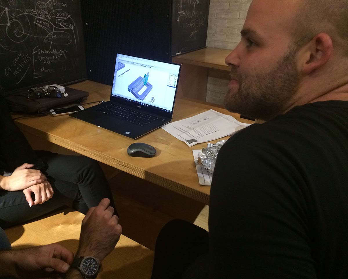
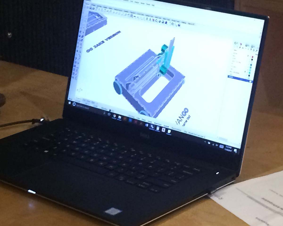
After class last Wednesday, we had an architecture section team meeting and decided to make a painting machine. The idea was to use Jake's frame and edit the parameters to a 20" x 30" bed (large standard watercolor sheet). We then split off into different groups and I joined the mechanical section which took on the design of the frame and axis, the set up of milling files and the fabrication. We started off by downloading the files linked on Jake's machine design gitlab page. We searched around in the folder and found the grasshopper files for the x-axis, y-axis, and z-axis but realized after browsing that the frame of the machine was not parametric (in terms of grasshopper constraints - Jake later explained that there is a way to use certain parameters in grasshopper, bake them and edit the model in Rhino).
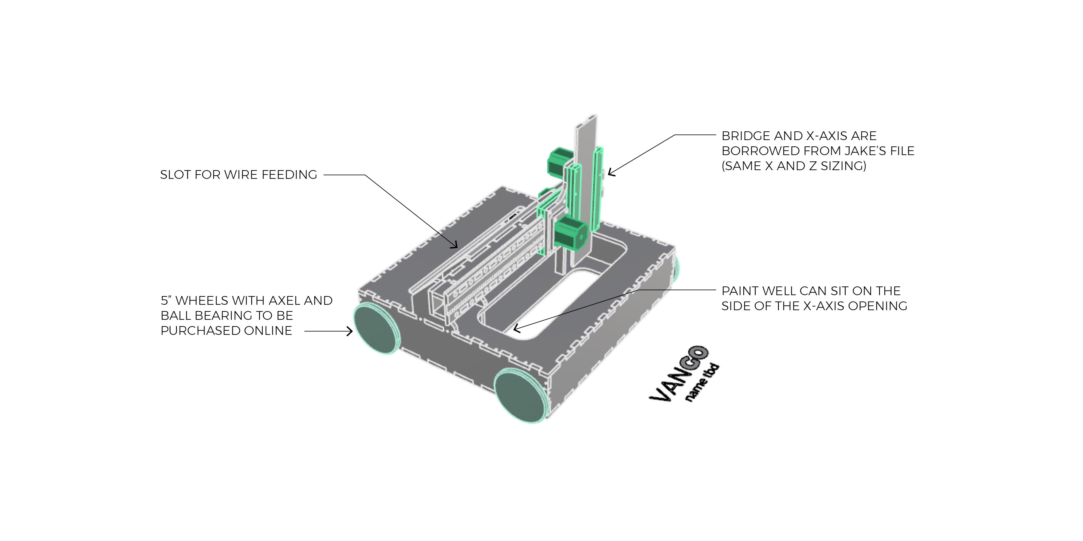
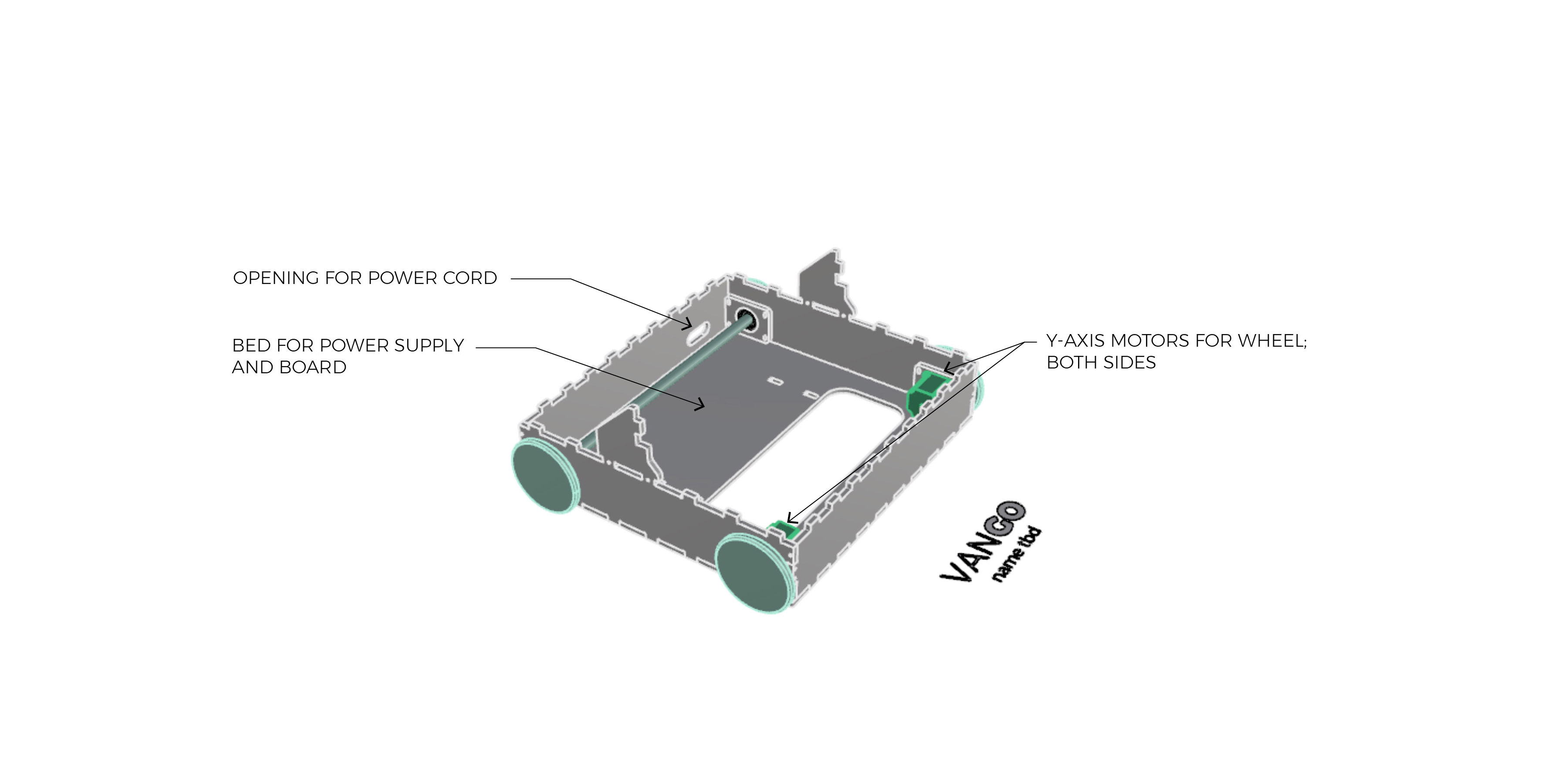
Becacuse we would be investing a noteable about of time for barely noticable changes, we decided to make the device mobile, allowing the y-axis to have an infinite length. As a team, we then proceeded to design a device on wheels which used the same y-axis motors for movement and the same x and z axis as created by Jake. The main concern for the machine was weight - weight in terms of the vertical load on the wheels and weight in terms of distribution for balance. One of the initial thoughts was to create a machine that has just two wheels to reduce the heaviness of the body. However, we felt this would cause balance issues as the machine moved. The final design contained a body for the power supply and TinyG along with a slot cut for the wiring and power supply.
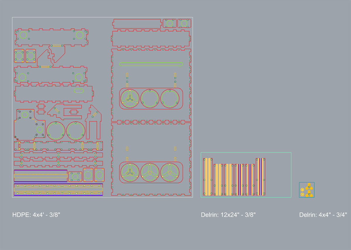
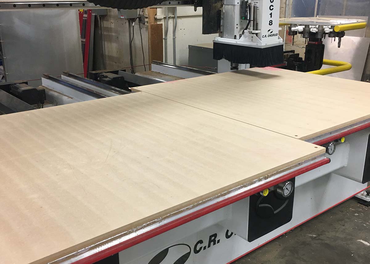
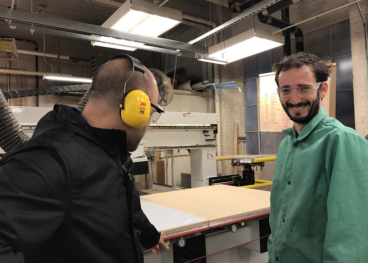
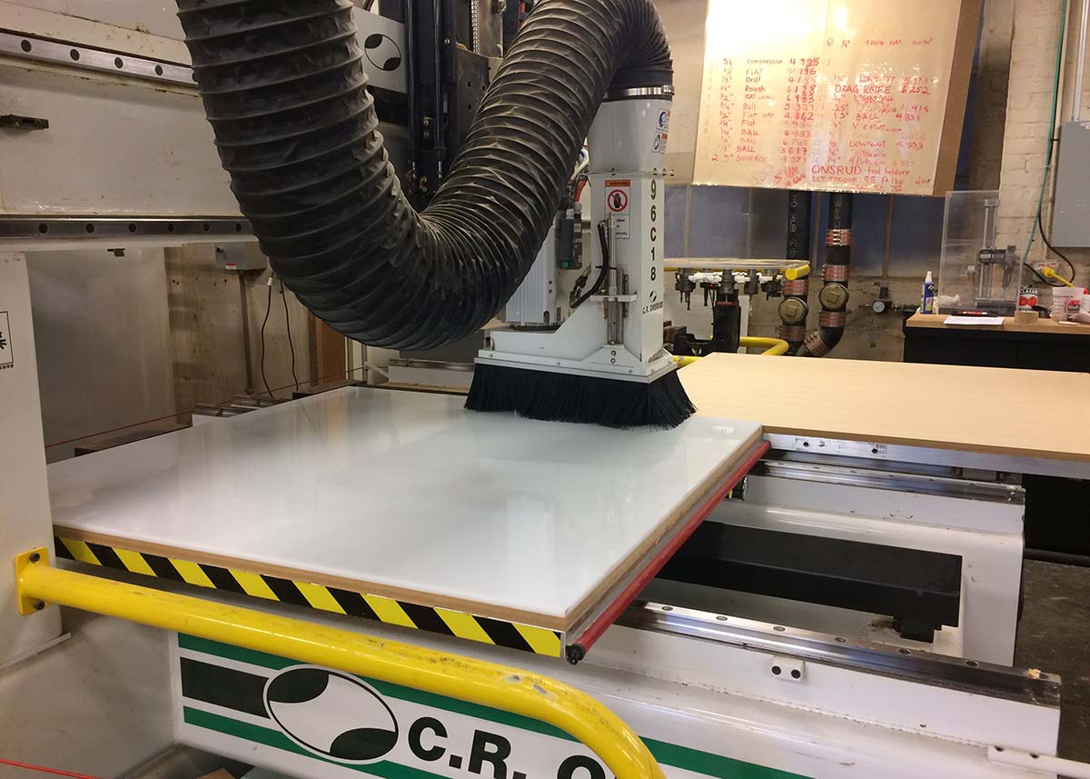
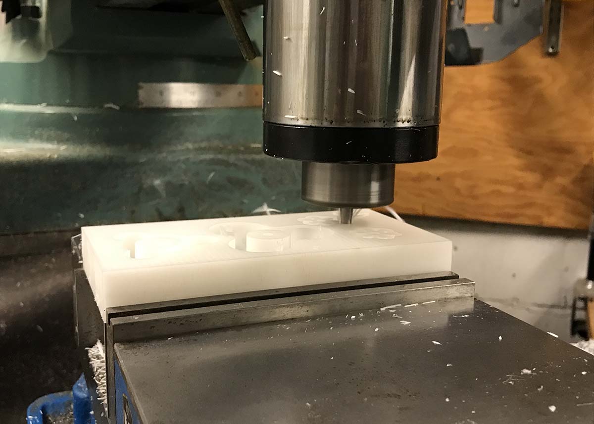
With much help from Justin, we first started by surfacing the sacrificial layer. After that was finished, we placed the HDPE on one half of the Onsurd bed.
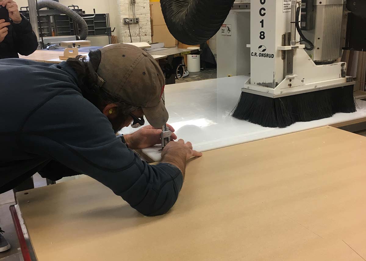
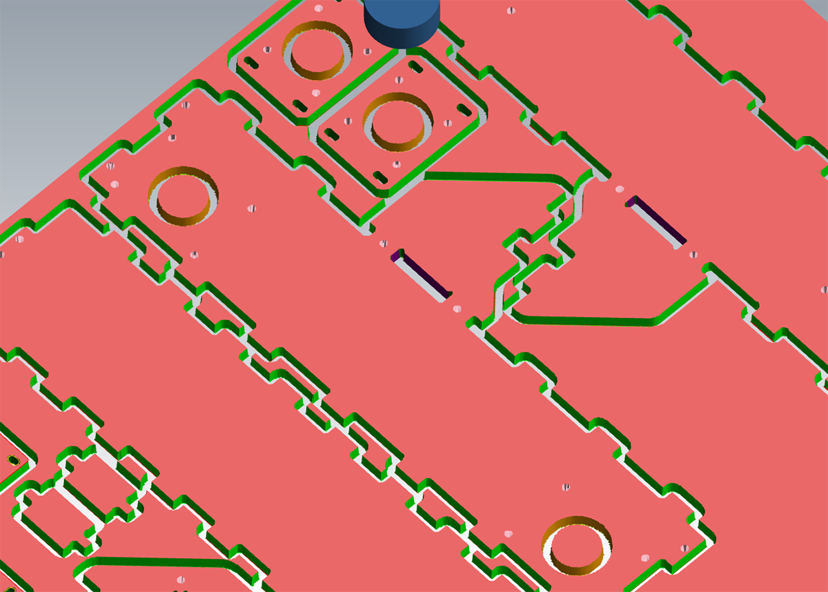
The first pass at 1/4" was a rough cut to the depth of the pinions - Justin suggested doing it this way so we would not affect the vacuum strength. If we did cut through before milling all of the pinions, this would potentially cause uneven cut depths. The next pass at 1/8" was a finish cut also to the depth of the pinions. We then did a similar rough and finish cut of the pockets, and finally did a cut pass for the outline of the parts.
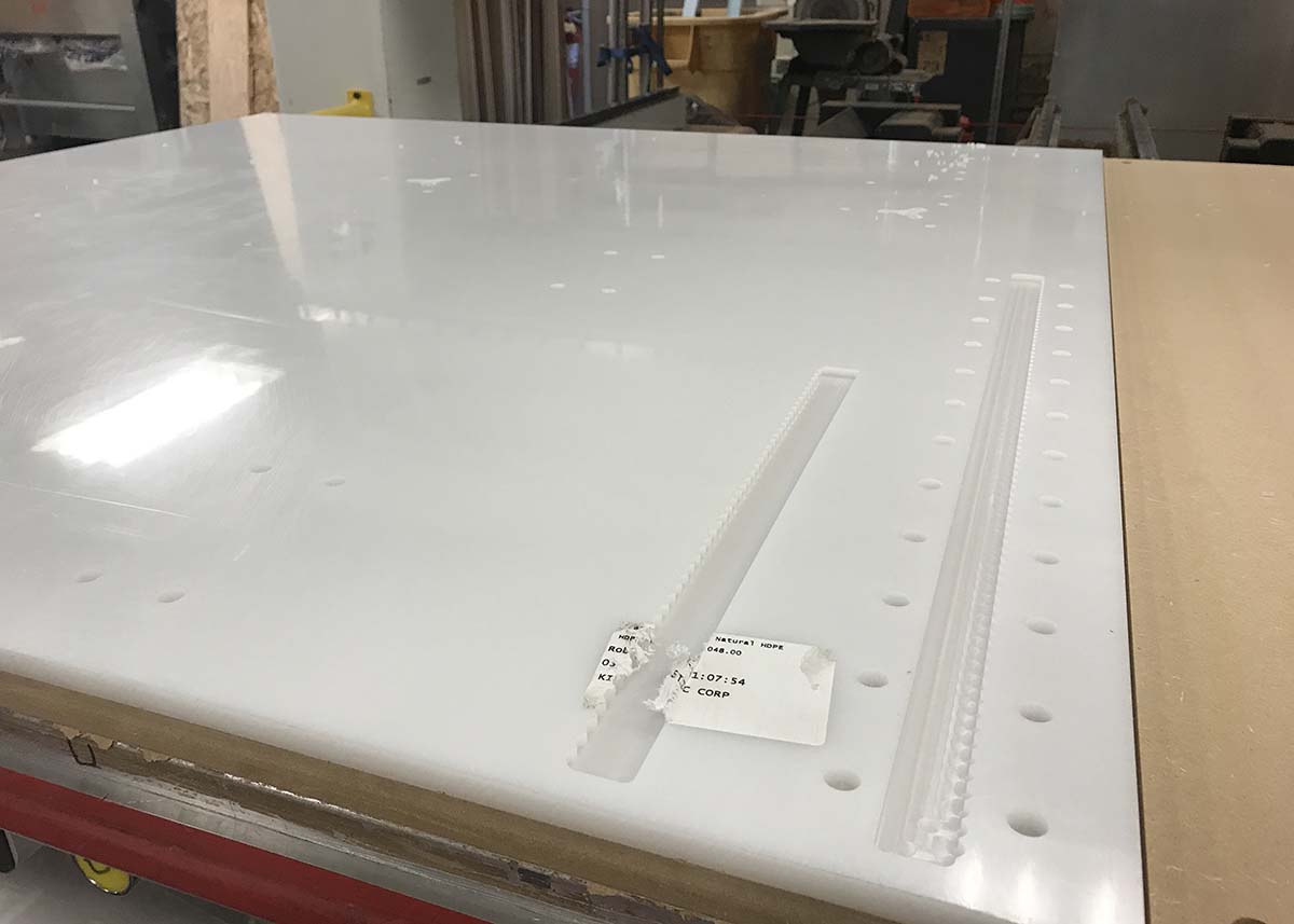
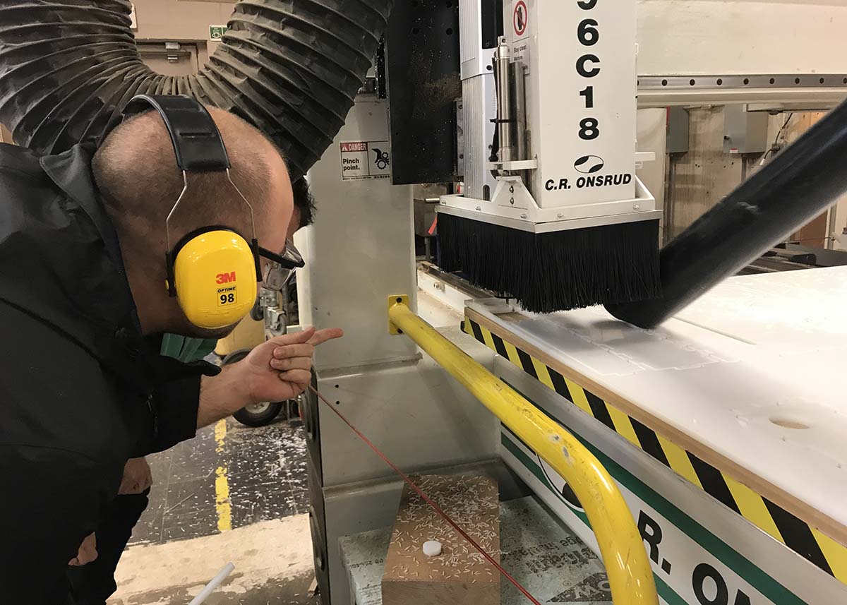
The final pass gave us several issues. First, the cut depth across the board was not even because of uplift at the corners of the material. Because of this, some of the pieces began to cut all the way through instead of having a thin layer of material to keep it in place. As a result, smaller parts because to move around and jam in the mill. Luckily, we did not have any significant damage to the parts but a handful were not cut properly.
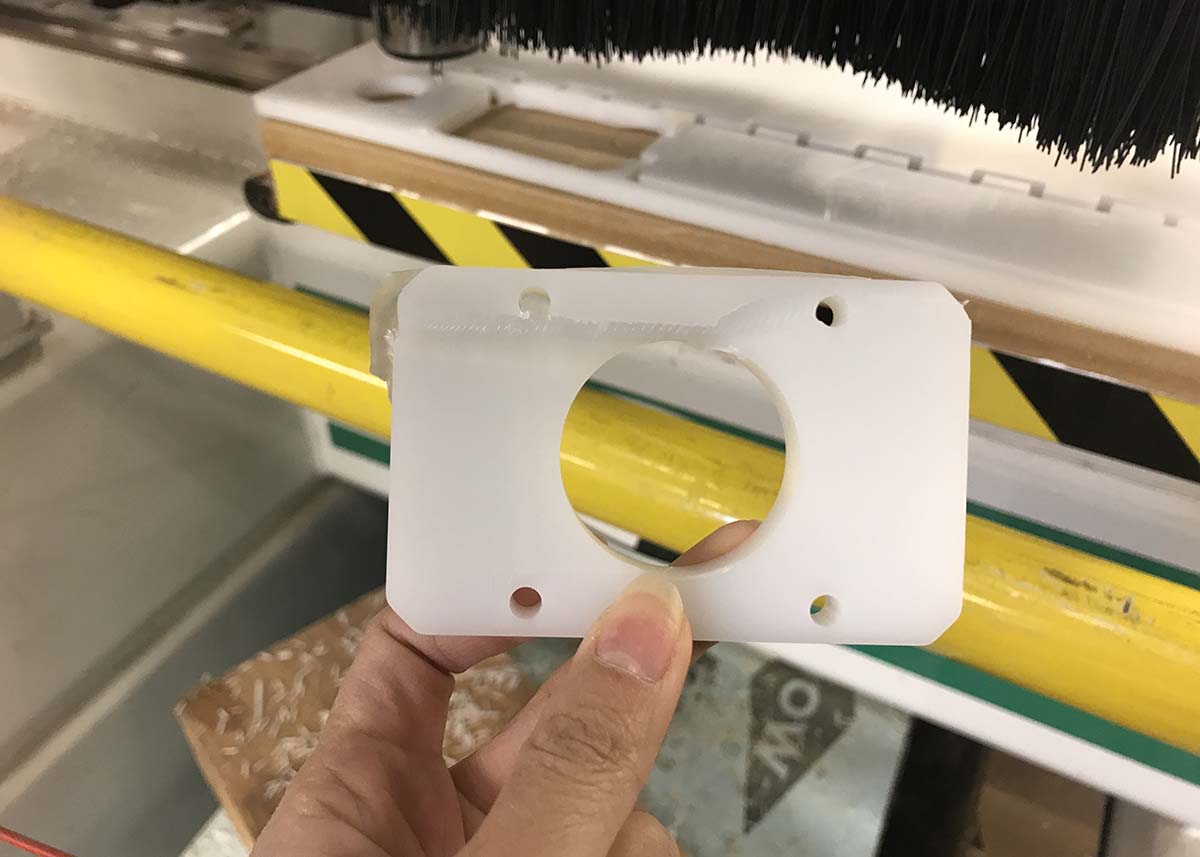
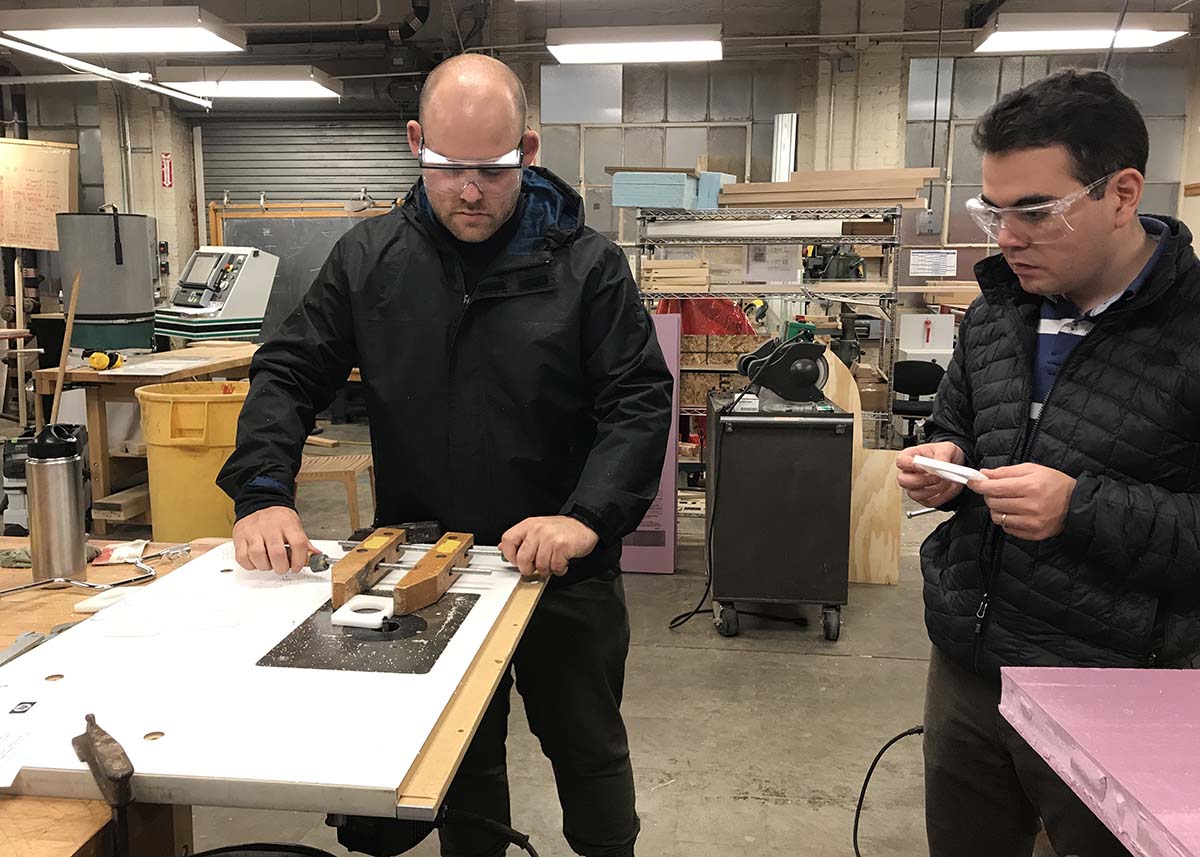
Because the pieces did not get a finish pass and several were not cut all of the way through, we used a router to clean up the edges on some of the parts. For the smaller pieces, we used a vice to grind down the edges and inner pockets.
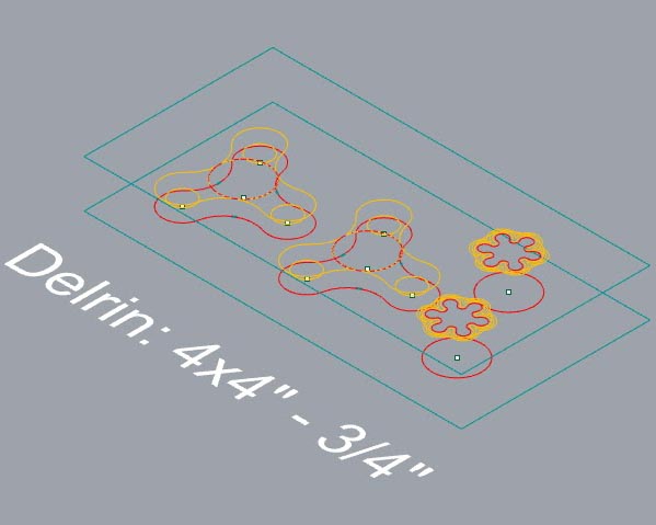
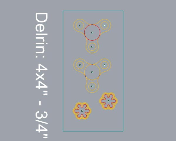
After that, we were done with the parts on the HDPE sheet and larger Delrin sheet. The next step, milling the smaller Delrin sheet, took quite a bit of time.
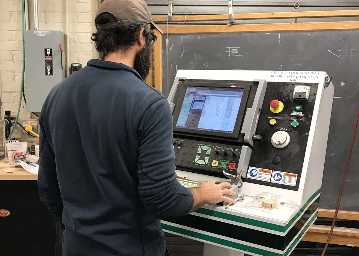
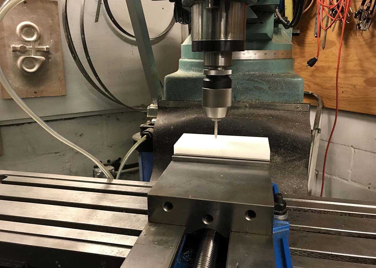
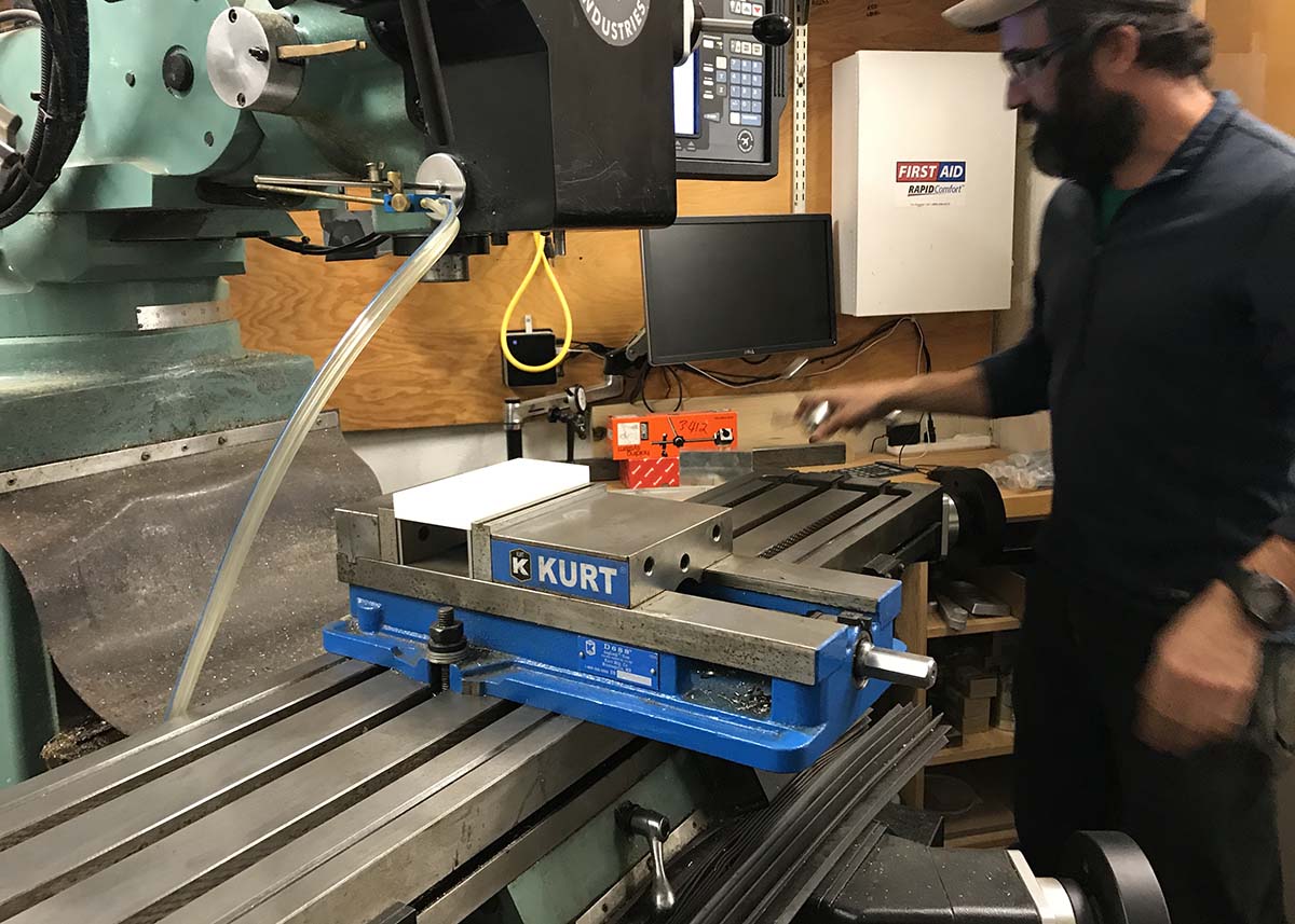
We milled the small delrin sheet on the ACME mill in N51. Because this required a small, 1/16" end mill, we were forced to run the job at 50% speed so as to not break the bit. This took over two hours to complete.

After that, our parts were finished! Or so we thought. We discovered several mistakes after handing over the parts to the assembly team. One, the pieces were not dogboned properly. The joints were copied from Jake's mill file and there was a false assumption that these connections would work once we milled. The tolerance was about 1/8th of a inch off and the assembly team was forced to manually correct the dogboned corners. Another mistake was with the parts attaching the motors to the body and axis. The pieces in Jake's file did not match the motors we were given and the assembly team recut those parts.
Other problems that we encounter were:
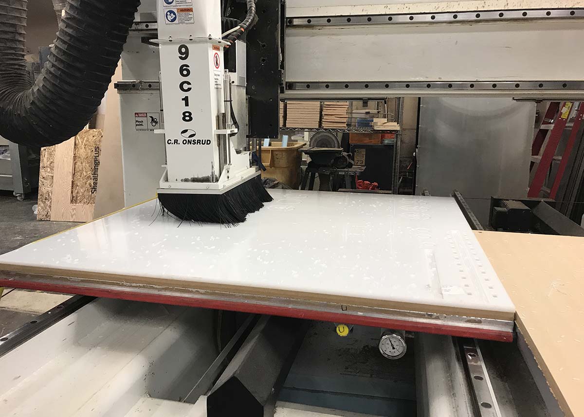
Pieces jumping out of place: For the first cuts, we program Mastercam so the machine will cut almost to the bottom leaving a thin layer of material that would keep the pieces together and in place. When the machine started to cut the final layer, some of the smaller pieces pop-up out of place and the machine cut some of them, which made them useless. Solution: Thankfully we had enough material to cut again those pieces, but for the second time we decided to leave the thin layer and cut it manually.
Pockets deep: To be sure that the deep of the pockets was the correct one, we decided to run first the pocket workflow. After that we measured the deep of the pockets, thankfully the cuts were correct and not further adjustments were needed. Dealignment of material in the cutting bed: While cutting one of the pieces the milling machine moved the material, this forced us to stop the process and align the material again. To do that from mastercam we selected two points or coordinates of some of the holes that had already being cutted. With that we manage to position the tool in this positions and align the material again. We also had to modify our process to only cut what was missing from our pieces and redo the pieces that the milling process damage.