Segments and Teams
End Effector
Computer Aided Design
Computer Controlled Machining
Assembly
Configuring the TinyG
UI - Chilipeppr
Power supplies
Putting it all together
Overview
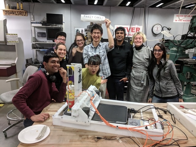
The CBA group is making a pancake printer! In order to do this, we've split into 3 sub teams, who will be dealing with different elements of the fabrication process.Makey Cakey Theme Song:
Idea
Our overall concept is an x-y axis 'plotter' that squeezes batter onto a hotplate. By timing the batter output, we can achieve a variation in colour, enough to produce a simple grayscale image. The form of the machine will be similar to Jake's machine, but will incorporate a 'squeezy-bottle' head and dispensing system to deposit the batter onto the hotplate. In order to ensure even cooking, we're using a hotplate we bought online, though an obvious improvement would be to integrate the hotplate into part of the electronics subsystem.Segments and Teams
mechanical team
Making and joining the physical parts that make up the machine- Yun
- Oscar
- Anna
- Safinah
- George
We started with breaking down the mechanical tasks in 2 parts, the physical structure of the machine, and the end effector.
Physical Machine Structure
We started with looking at Jake's grasshopper files, and modifying it for our pancake machine dimensions.
electronic team
Dealing with power management in the system...computer systems team
Dealing with writing an interface to the TinyG, and generating the pancake GCode from uploaded images.- Sean
- Emily
- Tomás
- Agnes
- Pinar
G Code
Key of GCodes, their meanings and guidelines is available here.CAD --> CNC Milling
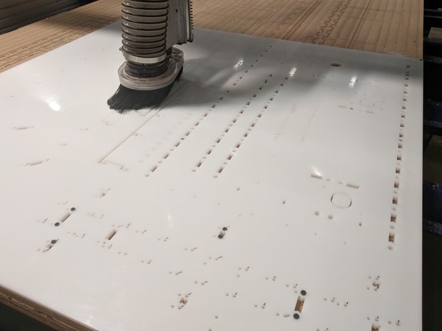
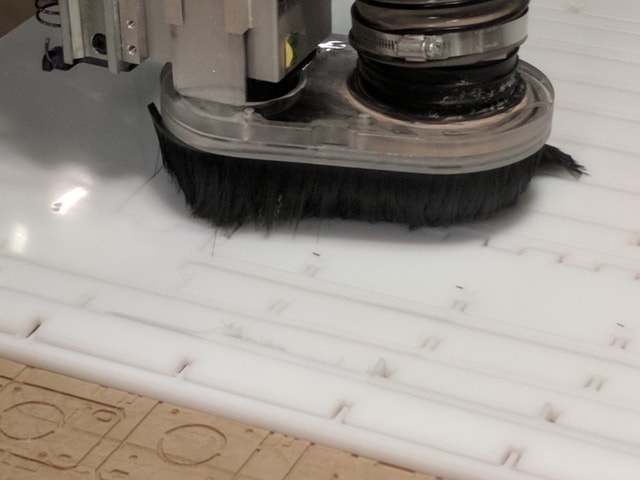
Preparing and then milling out the toolpath was far more exciting than we'd anticipated. First Oscar and George spent hours modifying Jake's machine to fit our griddle, and then unfolding it in Fusion to create the layout of parts for milling. Then they painstakingly created a bunch of CAM toolpaths, which involved clicking in the middle of hundreds of screw-holes on our model to ensure that the holes all got milled before the main pieces-- only to find that we could just use Jake's original toolpaths for the most complex framing pieces. We couldn't figure out how Jake made all the sketch-based toolpaths for the 45˚ angles, so it was an easy fix for Anna and Burhan to just copy-paste Oscar's modified parts into Jake's more complicated toolpaths.
There were nine different toolpaths to mill, involving three different endmills-- because Jake is a freaking genius who foresees everything and carefully optimized the whole milling process to mill the right things in the right order. Originally he even had four endmills, but realized that he didn't need to be quite so precise about optimizing the right tools for the right jobs.
Burhan, George, Anna, and Vik then had a series of
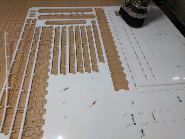

Anyway, the bulk of the milling was done-- all that remained was to mill out the pinions from the small piece of delrin. This was accomplished on Monday, and by Monday night the team had assembled the whole machine! There were, however, a few milling-related issues with the assembly since we forgot to put tabs on the skinny parts, and some of them shifted around and lost their precise dimensions. So the full assembly is a bit wobbly, but the pinion-and-rail system should still have its intended precision (since those parts were all screwed down).
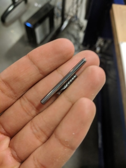
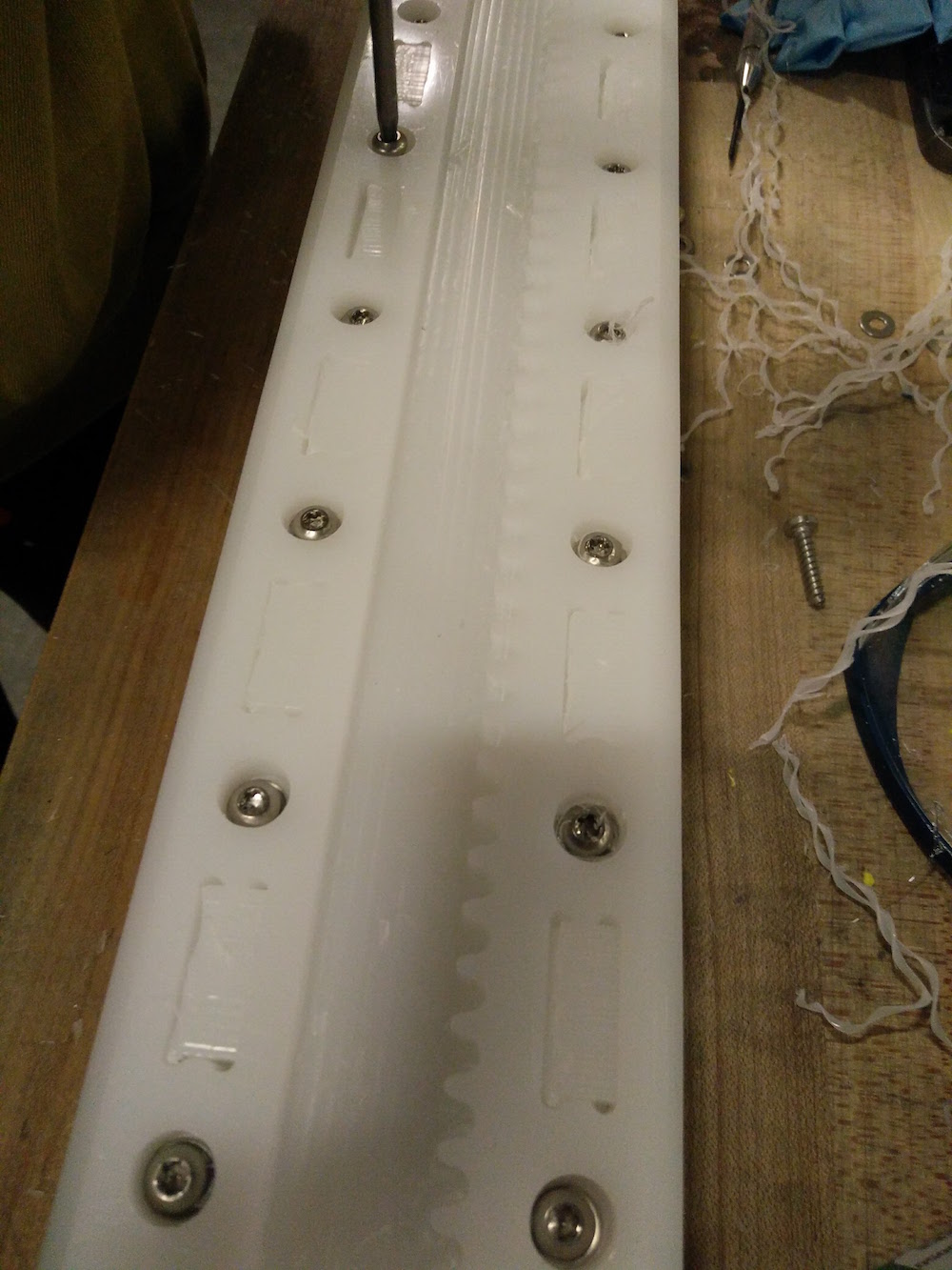
Delrin
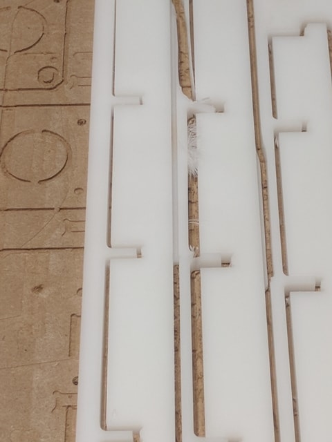
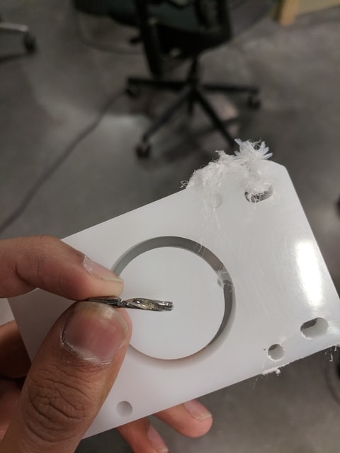
The Delrin rails were milled by Erin and Rui, who also encountered significant challenges. We thought milling the rails would be straightforward, but it wasn't. We created toolpaths from the files and export them as shopbot files so the computer could read the g-code files. Using the simulate function, We could see exactly how the tool would proceed in making the cuts.
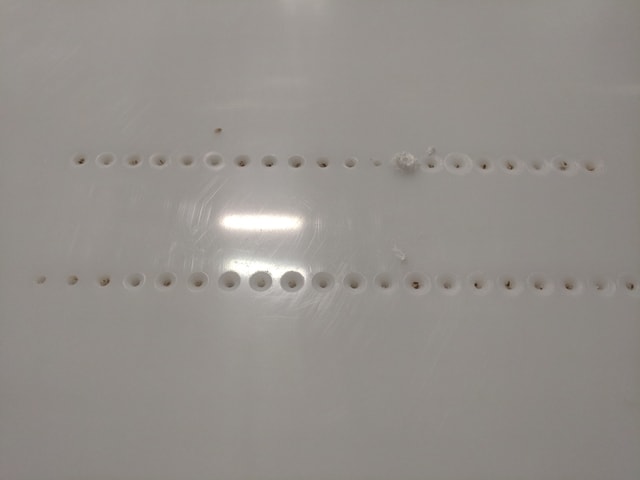
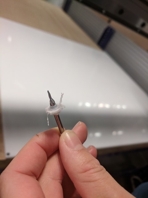
Each type of cut: boreholes, clear faces, contour and chamfer, required a different toolpath and in some cases, a different tool. Zeroing out the x, y and z and first cuts went well. Since we had only one 1/8th mill, due to earlier breakage while milling the HDPE parts on the large shopbot, we took turns, and when it came time to use the 1/8th mill several hours later, we made the mistake of re-zeroing the x and y axes without writing down their coordinates. We calculated the x/y location again, but when we made the chamfer cut, the location was not right and it damaged one of the rails. It took a long time to figure out what happened, but we finally did, with Jake Reads's help. Apparently, all we had to do was relocate the x/y axis on the Fusion file and re-export it as a shopbot file. This solved the problem and we were able to resume milling. We had to screw down the rails in order to do the contour cut. We had to use a small remaining corner of the delrin to place the remaining rail, and went through the whole process again. After the delrin rails were cut, we realized the sacrificial layer was not level, it was beginning to come apart in the middle, raising the surface slightly. This resulted in an incomplete cut which required post-processing in the form of deburring.
Assembly
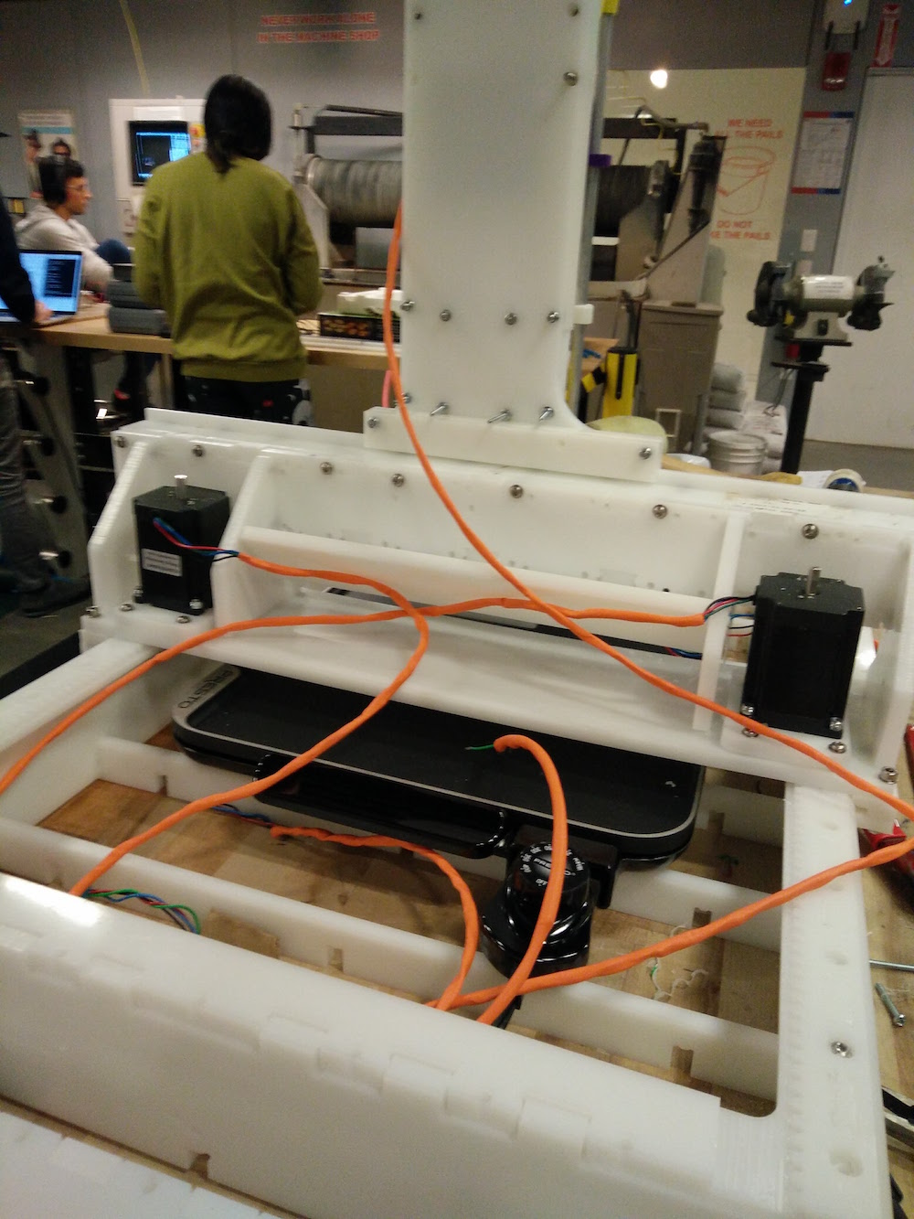
The assembly was done by Vik, Safinah, Oscar, Yun. We started with assembling the base the night of the milling. When we attached the walls to the base, it because wobbly. Next morning we decided to let go of the vertical beams as the base was pretty stable on just the walls and the horizontal short ribs. We then made the top two parts, one that holds the y-axis motor, and one that holds the end effector.
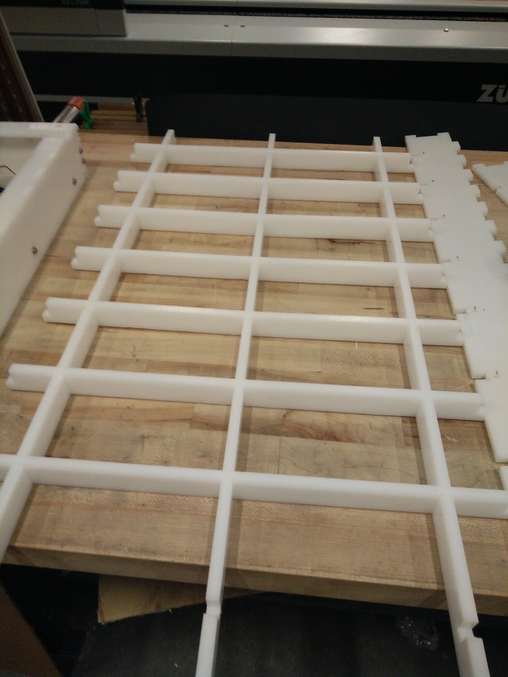
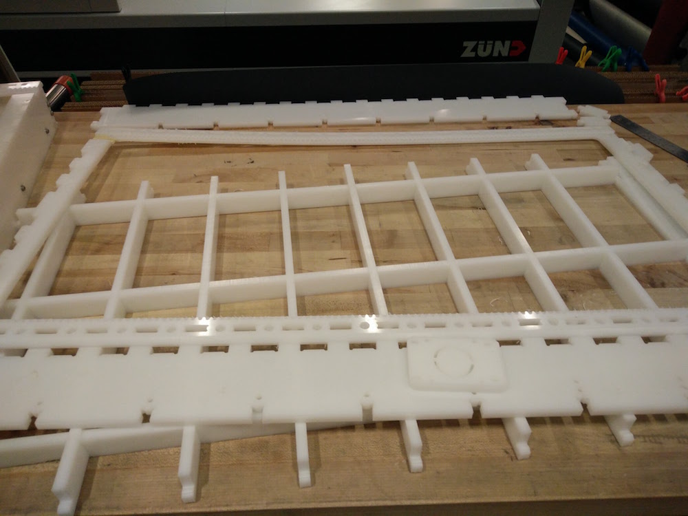
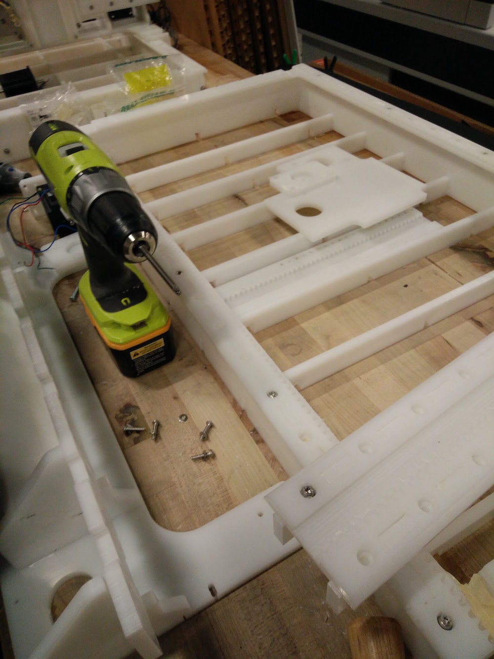
While inserting the y-axis part along with the end effector on top of the horizontal base, we realized that it was getting to heavy and bending the whole thing down towards the base - so we had to nail in the triangular parts to the vertical walls of the y-axis motor part. So as you can see we drilled in extra holes using a hand drill, and put in nails to hold the y-axis motor and end effector in place. We also realized that the pinion was not touching the teeth of the sliders, so we had to remove and move the motor slightly up by half an inch and drill new holes.


We then put together the end effector part. We needed some amount of removing and glue gunning or the corner yellow triangles since it was tough to hold them in place. Throyghout the body we did a lot of extra nailing to be able to hold the body parts together. We tested out all the 4 motors in the physical structure. The z-axis motor did not work. We tried to troubleshoot by relacing the y-axis with the z-axis extruder motor, and it worked. So, we realized that it only needed reconfiguring of that motor. After configuring it, all the axes worked and the machine was functional.
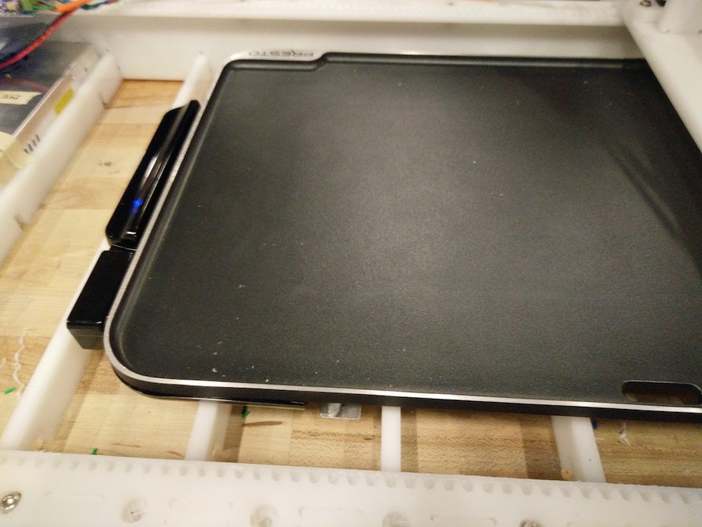
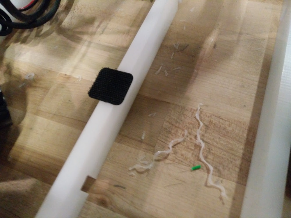
We then used velcrow to stick the griddle to the bade and hold it in place for the pancakes.
End Effector
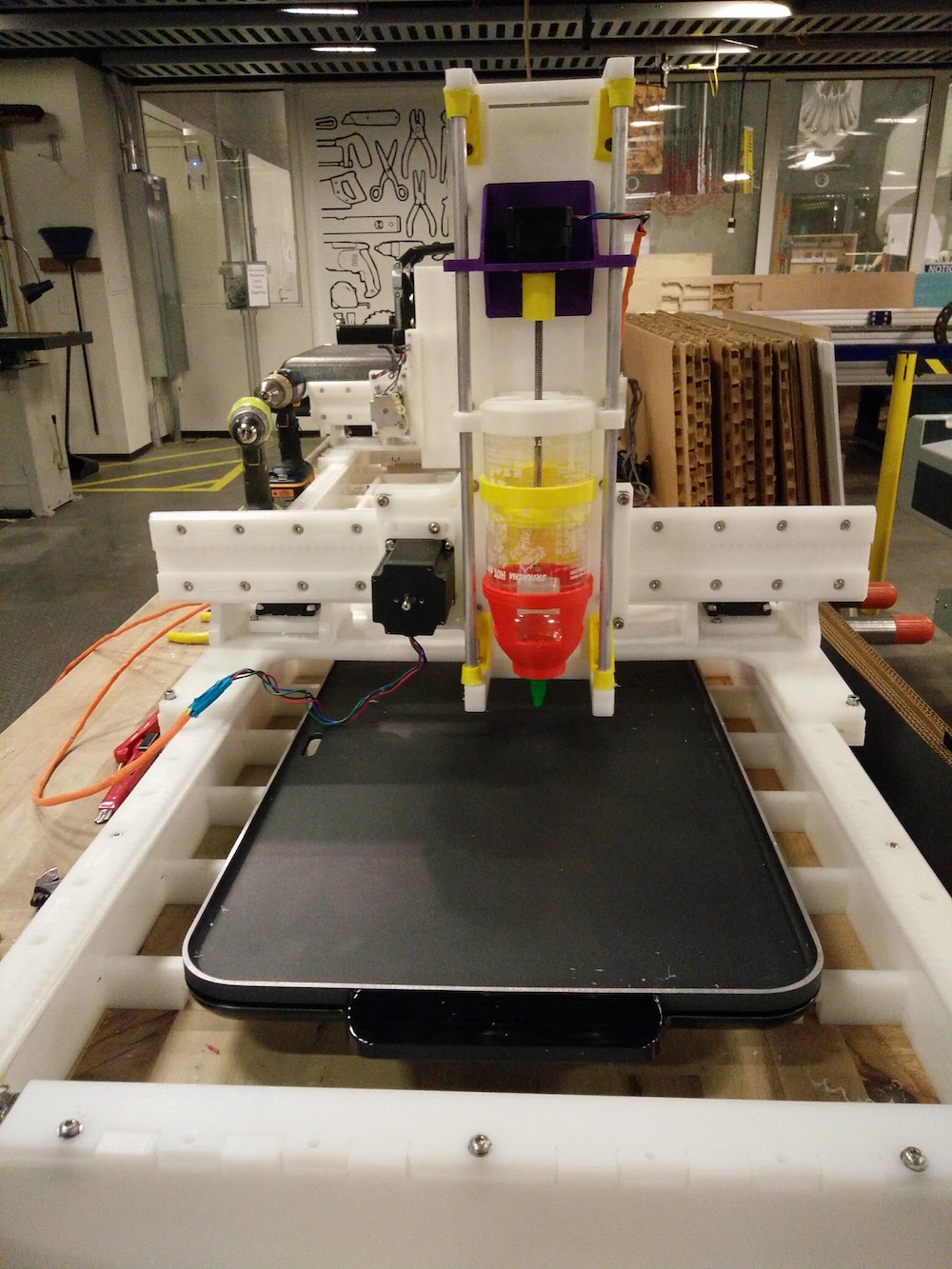
We looked at tube like structures that can be pressed / compressed to make an end effector to drop the pancake mix. We could either use a motor and a ring to press the tube, or we could use an air pump motor to compress the liquid and drive it out. We built both!
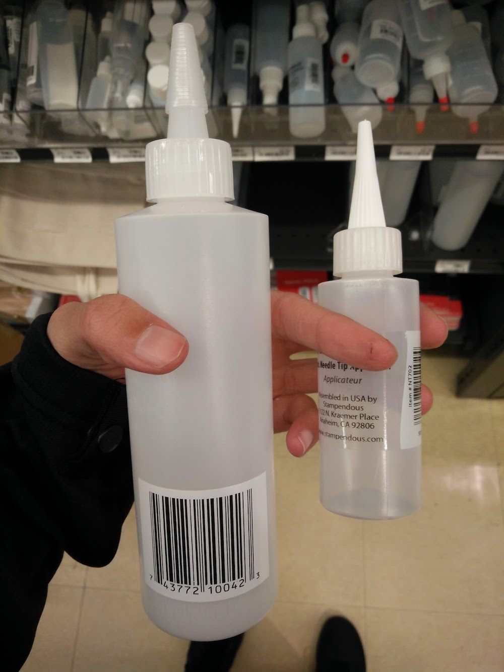


Safinah made a squeeze bottle with a servo that pushed a nail in ad out of the side.
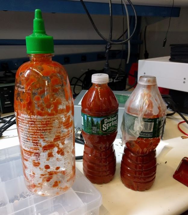
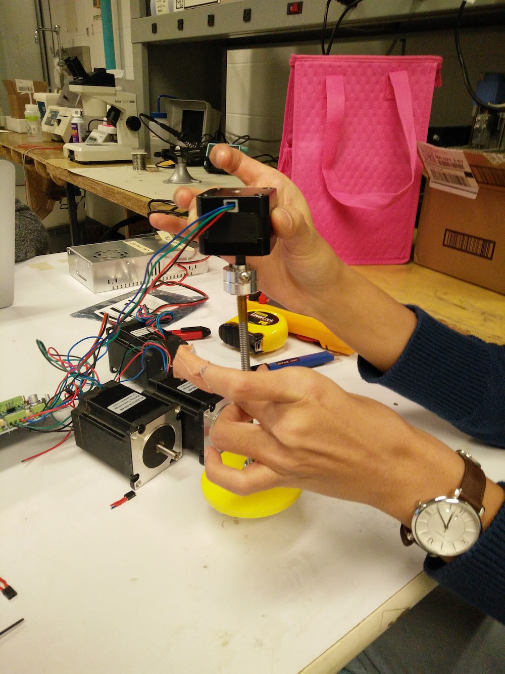
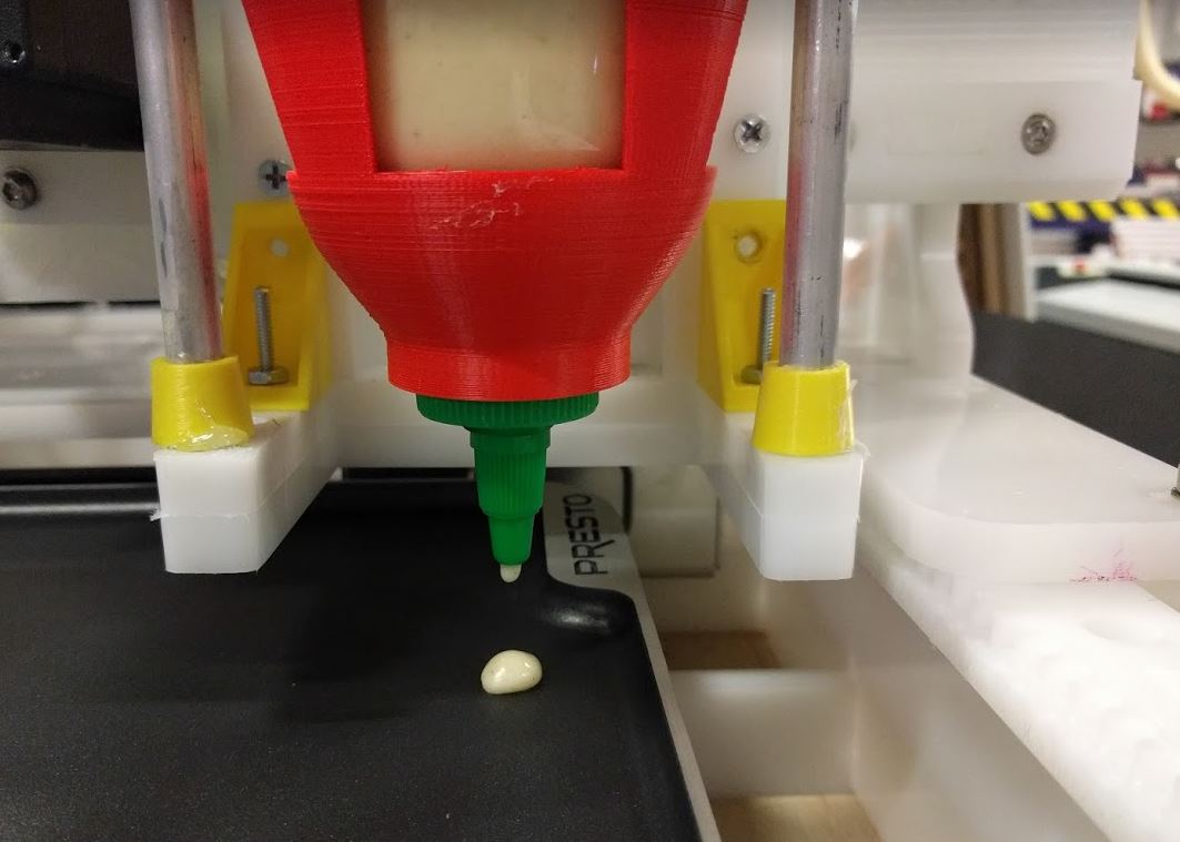
Yun used a air pump and a Sriracha bottle to build a pressure based system.
One of the issues raised was that, as the board only takes GCode, it's hard to integrate timing logic in the form of a chip. We needed a controllable motor to keep the end effector from leaking batter continuously. We discussed our two pump designs, and had to figure out how to run the motors of the end effector using our TinyG board... could we just use what the TinyG thinks of as the Z-axis to control the release of batter? This could use a stepper motor rather than a linear actuator, which would be much easier to program! Here’s an example MakerBot contraption that pushes a syringe up and down using just the basic Gcode. The difference is, these folks are moving their entire unit up to make the syringe go down-- but we will be only moving the piston low, and keeping our sirarcha bottle static.
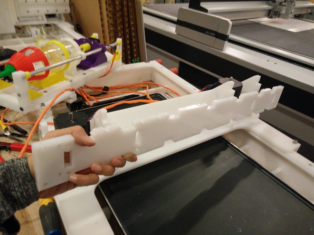
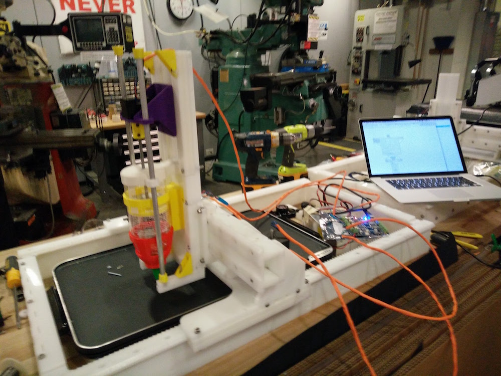
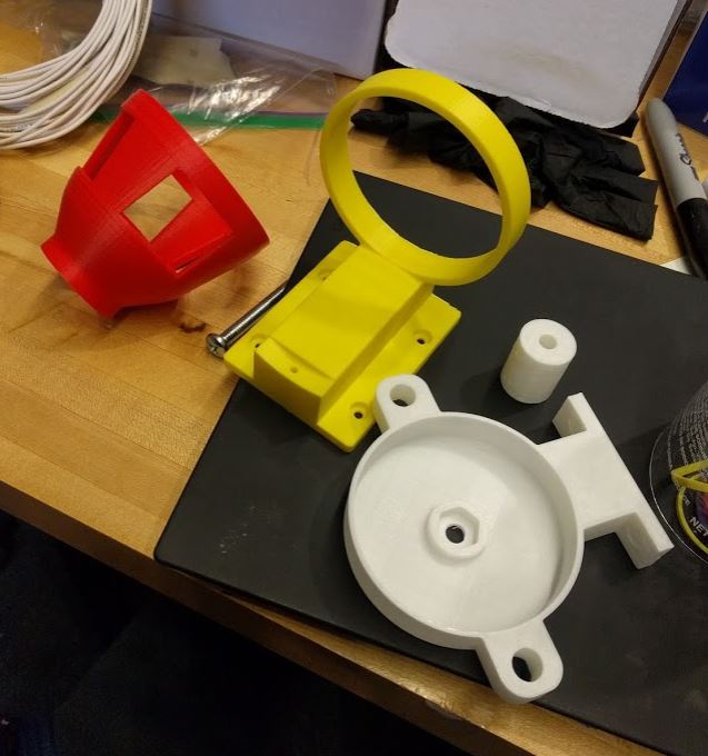
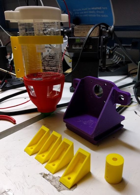
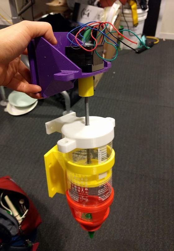
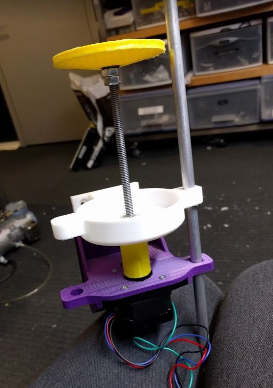
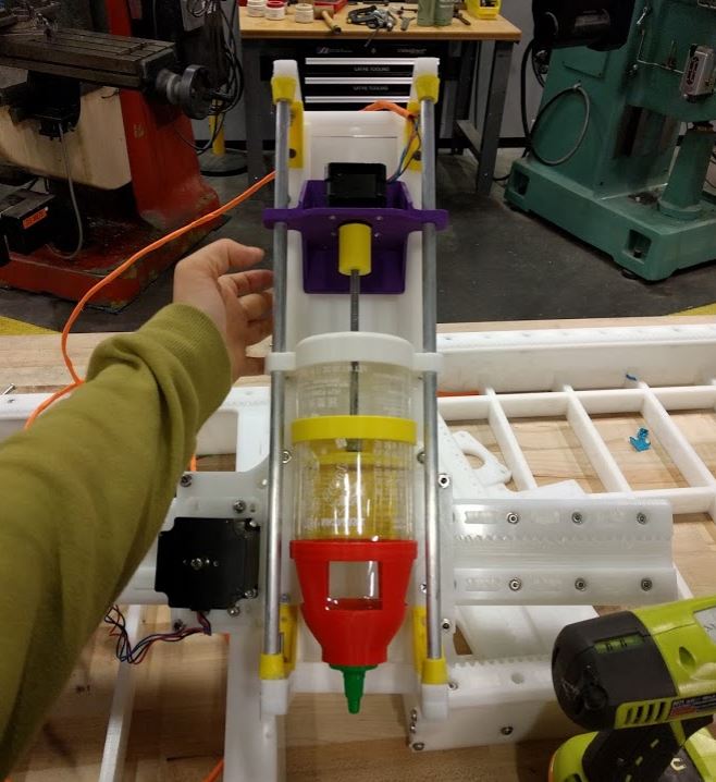
We decided to go with the sriracha bottle contraption, and Yun got started on modelling and 3D printing the bottle holders and Safinah made the motor mount structure for the motor rods to go through the T-nuts.

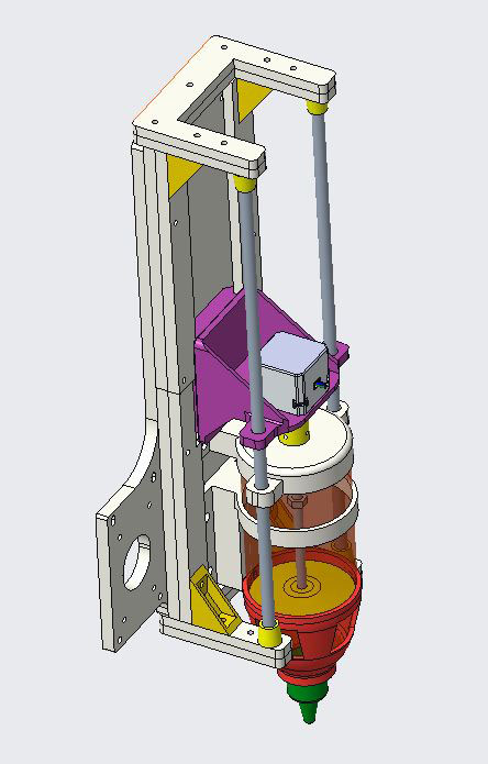
To support the z-axis motion of the stepper motor that change the height of the piston in the Sriracha bottle, Yun designed the rails that go through the motor mounts and the bottle holder.
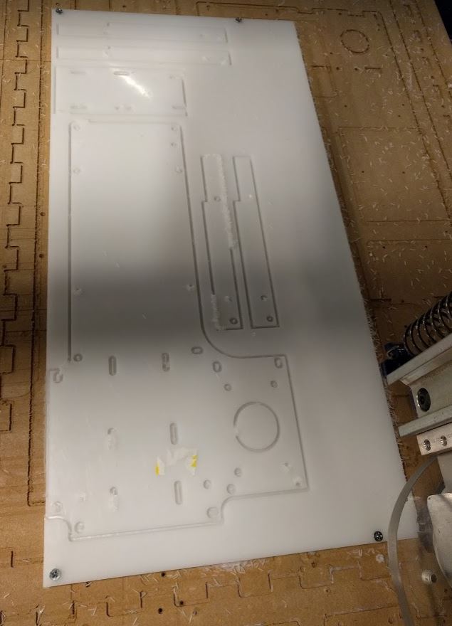
Also, to integrate this mechanism and structure, she modified the Jake's design of z-axis plate and CNC milled the HDPE sheet.

After all the assembly is done, the y-axis rail had to be assembled to the z-axis mount with the extruder since the extruder was too long to go through the workbed.
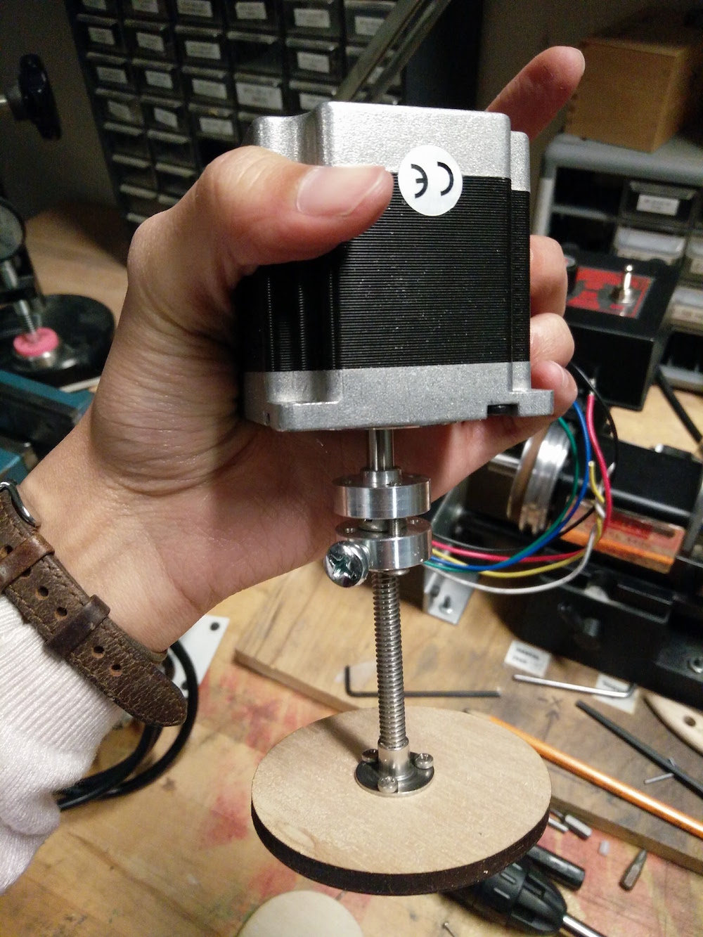
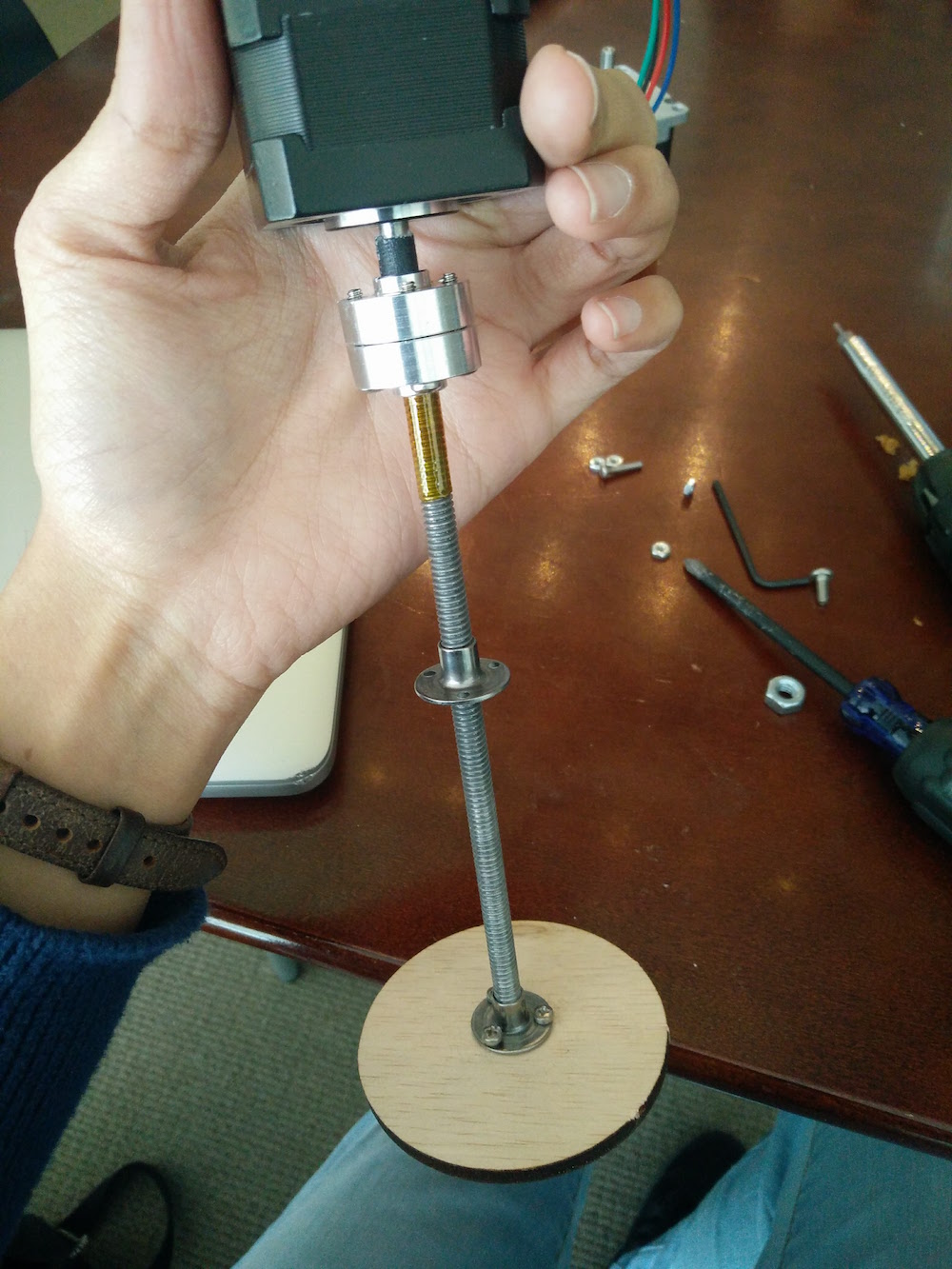
Z-axis test We used a 4/40-20 threaded rod to turn the stepper motor (the rotational motion) into a linear actuator (linear motion) and connected it to the motor shaft with 3D printed coupler. As the motor rotate one step (1.8 degree) the piston moves 0.70 mm.
Generating GCode from Images
We planned out the goals to getting the software writing out exciting pancake GCode. The goal was to generate several paths at different darkness values that the machine would then extrude in order from darkest (longest cooking time) to lightest. Two key problems that we faced were timing and rastering. Timing is important in getting a good distinction between colours. The basic flow went:- Input PNG
- Reflect image to make pancake right way up
- Transform image to greyscale
- Separate PNG into different layers
- Black (outermost) is vector
- Others are raster
- Convert PNGs into GCode
- Merge them together separated by dwells
- Concatenate with TinyG configuration
- Send via serial port
Reflecting
To reflect the image, we modified the web worker activity of an existing image mod to perform a pixelwise reflection. The mod loads the buffer values into an array, then reads them off again, reversing the direction and flipping the image in the x-axis.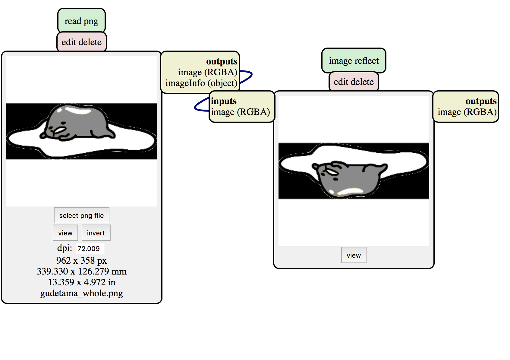
Greyscale
Greyscale mod to pre-process image to be thresholded.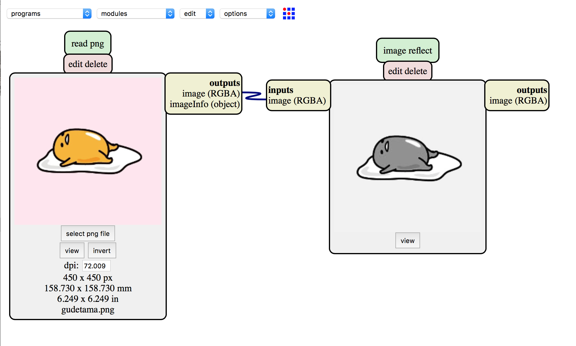
Thresholding
This step is key to achieving colour variation in the pancake. The darkest values need to be generated first, and the path encoded as a vector (a black outline), with successive shades (hopefully up to 3) separated and rastered, with pauses inbetween. In order to plot these paths, the image must first be thresholded, and separated into different layers, which form 'blocks' of GCode separated by pauses.
We were able to extend fab mods thresholding to threshold the image. We needed to edit the javascript to allow us to use a band-pass filter, rather than just low-pass, as the thresholding would have to select one greyscale level at a time. added 2 boxes -- input hp and input low pass. added to object called ctx, send to the web worker. web worker computes pixelwise. instead of doing just one comparison --
if i < hp and i > lp.
Gcode Concatenation
We started with a simple mod to concatenate gcode together (with a custom dwell time in between) as a way of combining the various toolpaths. This was a decent proof-of-concept but we ended up abandoning it later in favor of generating custom Gcode for the TinyG.Configuring the TinyG
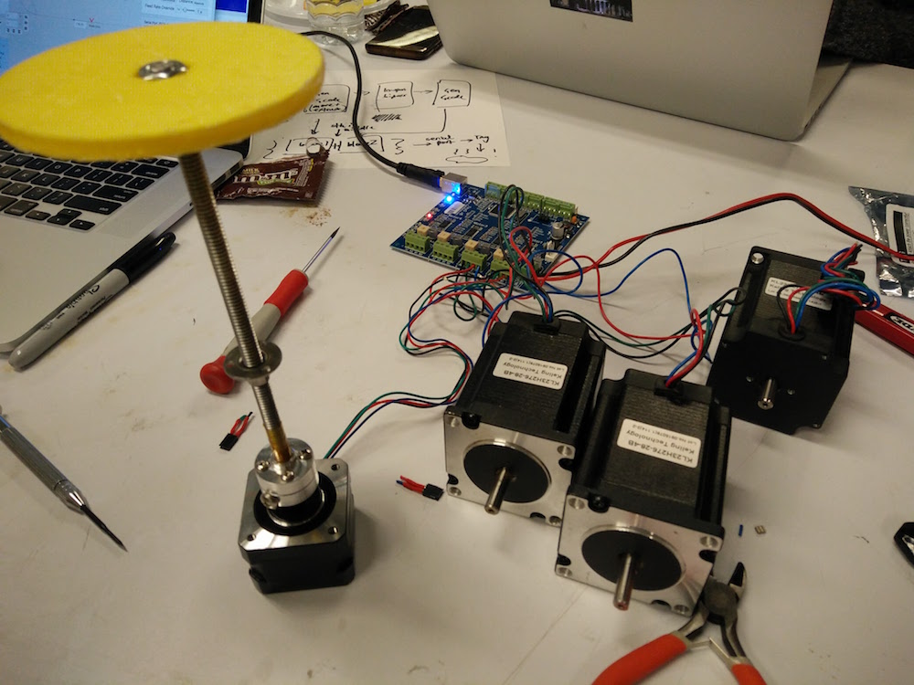
The tinyG board allows up to 4 motor groups to be defined and configured separately. We're using the firmware 0.97 version. The TinyG takes GCode one letter at a time through a serial port interface at 115,200 baud. To write a UI, can also use JSON. For the machine, we're using a set of 3 motors to drive the x-y motion (one on either side of the x-axis, to avoid the need for power transmission), and a 4th to drive the pancake-dispensing piston. The drive motors are the heavier NEMA23 models; for the batter dispensing, we've opted to use a lighter NEMA 17 so as not to stress the z-axis unnecessarily.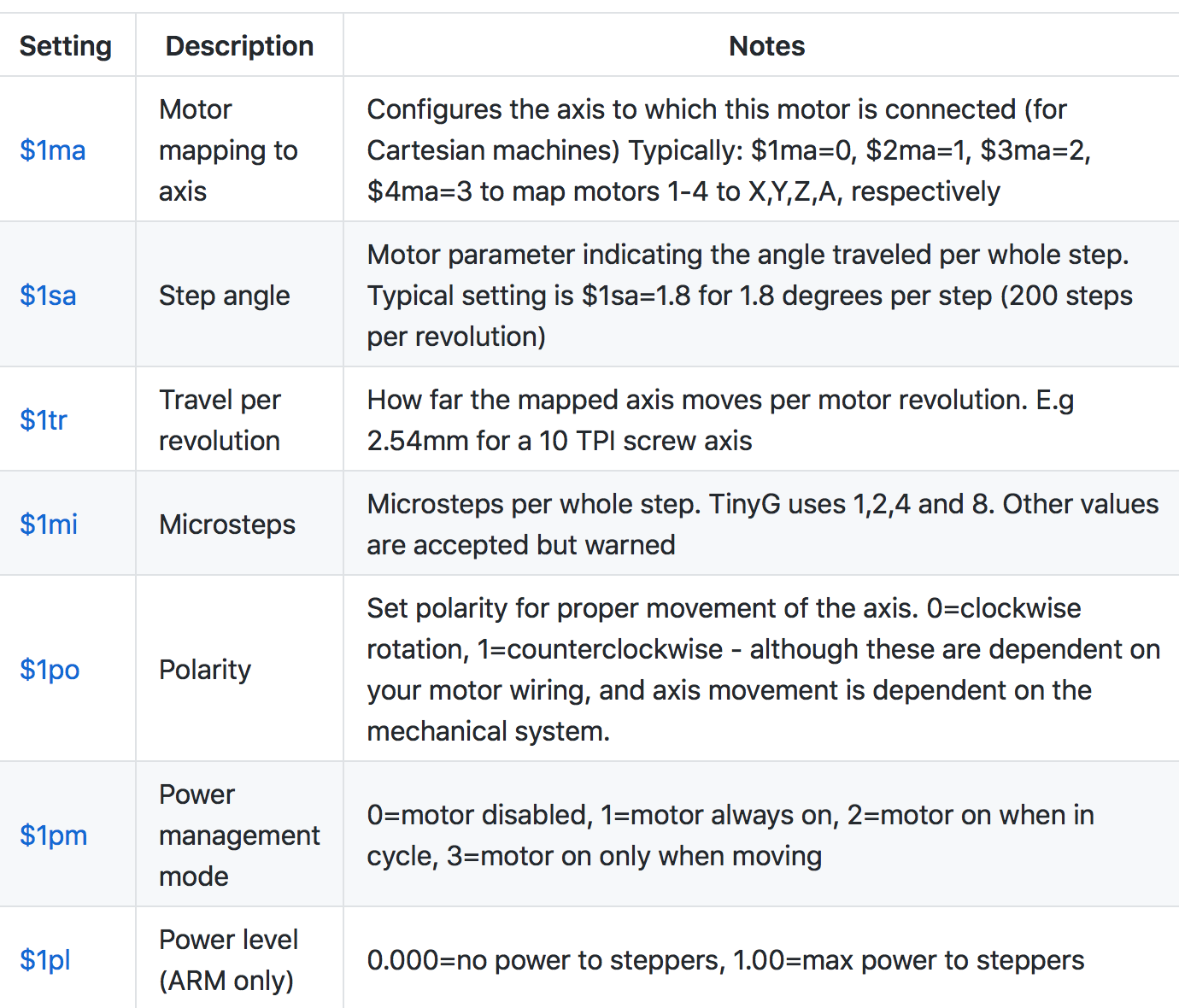
TinyG provide a detailed and very helpful configuration guide here, and a guide to JSON configuration (for custom UIs) here. Some values (like the step angle for the motor), are available from the data sheet. Others, like travel per revolution (the distance a mapped axis moved per revolution of the motor) depend on the mechanical configuration of the system. TPR is a motor property, rather than an axis property: one could theoretically have 2 different gearings of motor driving the same axis, giving a different 'travel per revolution' for each.
TinyG Mod
We ended up building out a custom TinyG mod that allowed us to jog around the machine, send commands to the TinyG, and receive (and parse) returned data. Along the way, we ended up added gcode generation into the TinyG mod to give us more control over how the different parts of the gcode were being generated.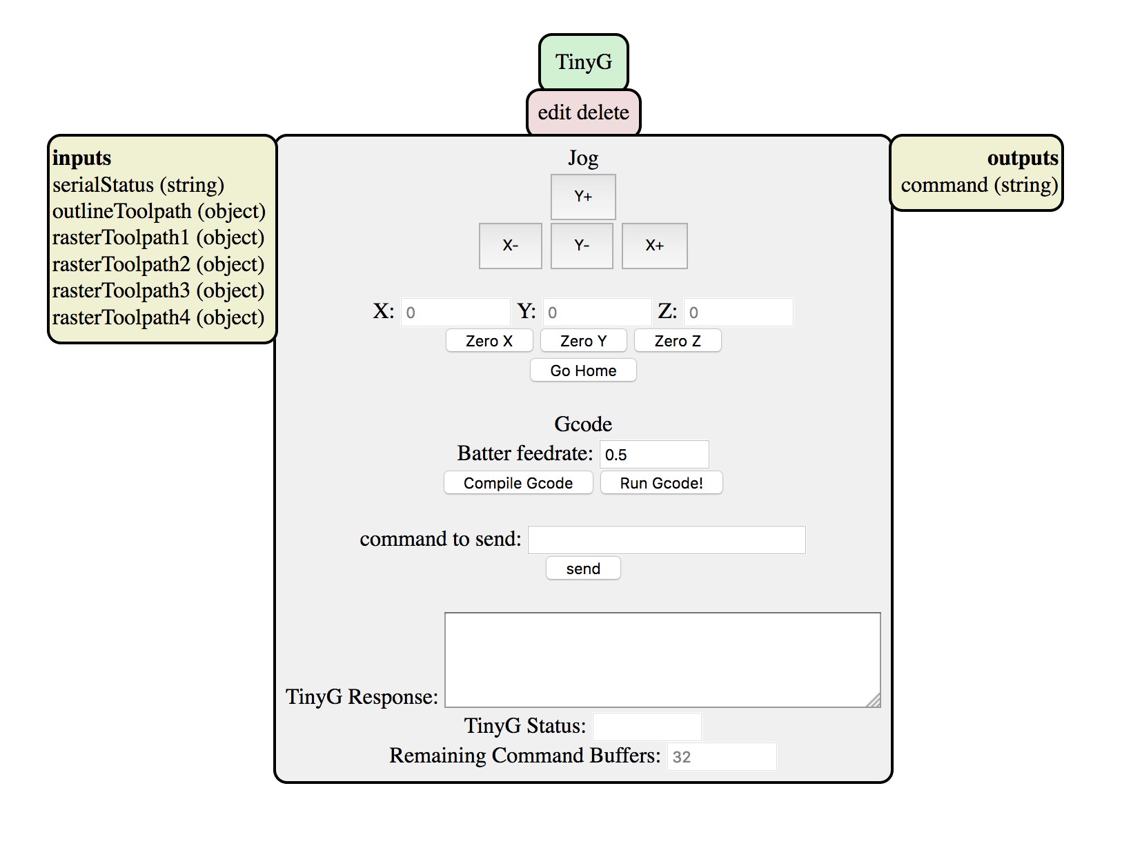
Mods Program
These mods allowed us to build out a complete mods-based UI for controlling the pancake machine. It was...big but worked!Pancake Batter
Erin made the pancake batter, in two batches of gluten and dairy-free. Using lessons from clay 3D printing extruders, she experimented with the consistency of the batter. The Siracha bottle nozzle created a constraint of a tiny hole for the batter to pass through on its way to the griddle, living little room for lumps. Using Bob's Redmill mix a thicker batch was mixed, and then a slightly thinner batch was run through a blender to eliminate clumps.
Power Supply
Motor controller needs to be powered at 25 volts
G-Code into machine
Problems with establishing co-ordinate system. First thought: using wrong GCode flavour. Next looked at the absolute commands, whichwiring
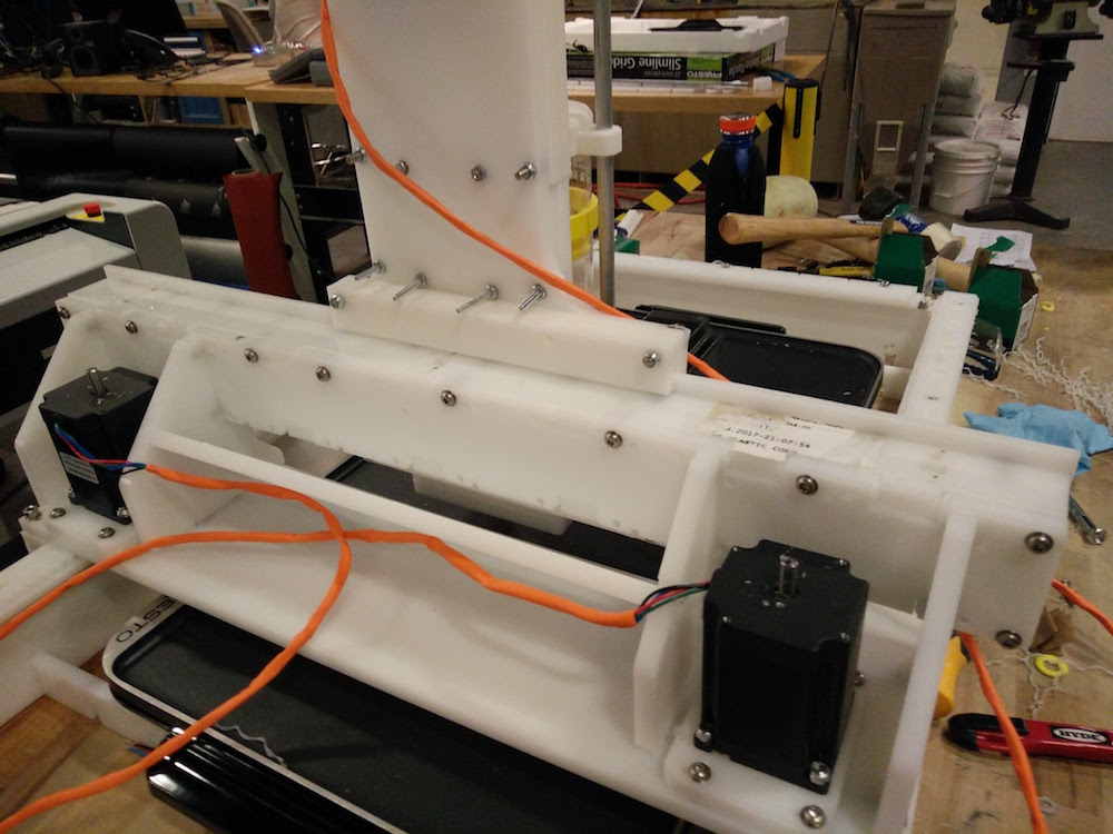
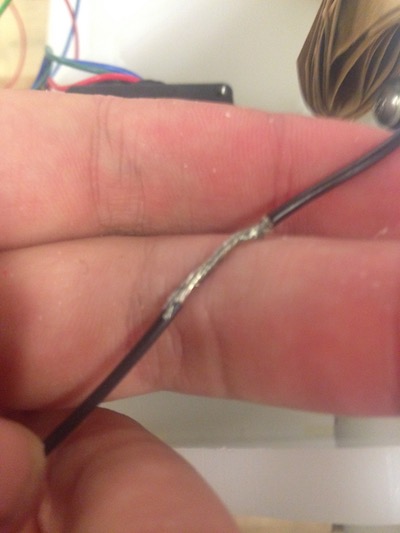
The motor controller needs to be powered at 25 volts, requiring a large power supply. The first thing we needed to do was to fit longer wires to plug the unit into the wall. The cables coming from the TinyG needed to be arranged so as not to get in the way of the machine, short on one another, or break. The first thing that was needed was to lengthen each of the motor wires (12 in total) to allow the axes to travel the full length of the bed unhindered.First, the wires (which needed to be multicore wires, ideally of the same gauge as the wires from the stepper motors) were stripped about a centimetre back. For each joining pair of wires, the multicore strands are frayed out slightly to allow them to be pushed together, and then twisted to hold them together with friction. A smear of solder is added to each join to ensure that the wires stay twisted together. After that, a heatshrink sleeve is pushed over each join (leaving a centimetre on either end to ensure wires don't short against one another), and the heatgun is used to seal the sleeve tight.
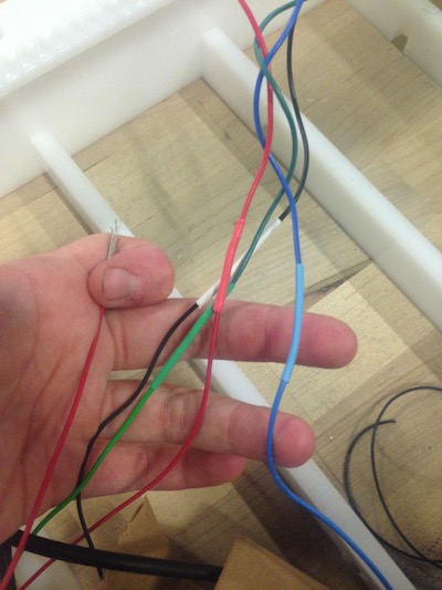
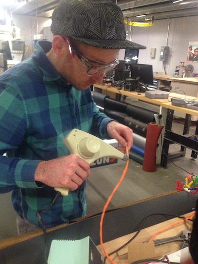
Initially, the wires were twisted together in groups of 4 for each motor -- then Vik found a roll of giant orange heatshrink upstairs, so we used that to clad each of the wiring groups. This made the machine a lot easier to deal with (both visually, and physically). Testing the termials of the TinyG (before we plugged everything in) -- we got worried about the fourth (smaller) NEMA 17 motor, as unlike the other motors it did not show a short circuit between the blue and red, and green and black wires respectively. (as it should)
It turned out that this was because of the finer gauge wiring (and possibly internal resistance): the resistance between these 'connected' pins was actually in the region of 30 Ohm: reasonable for the motor, but too high to be picked up by the multimeter as a connection.
integration
Everything works independently and the batter even pours smoothly, but the full integration of the machine and code hasn’t quite come together yet... it may be some sort of calibration issue. But Makey Cakey is almost there!