Project Planning
We met on Thursday to discuss our plan for this week. We voted on the following ideas: a 2D cake frosting printer, a pen plotter, a circuit testing multimeter probe, a pancake/salami delta picker, and a chocolate mill (with heat) or cutter (with a spindle). The delta picker won! Then we realized we could realize basically all of the other ideas with the delta picker with different end effectors.
We divided into five teams: design/CAD with Andrew, Niki, and Priya; arms/joints with Elysa, Kaspar, Natalie; end effector with Casey, Genshaft, and Xin; control logic/programming with Vibha, Ben, and Max; frame manufacturing with Robert, Nikita, and Eleanor.
Since our lab was closed all day Friday and Saturday, the earliest we could come in to work after designing was 1330 on Sunday, which is what we did. We got our start from Jake's design.
CAM Files
Parts of the rail/carriage:
- Part 1
- Part 2
- Part 3
- Part 8
- Parts 4 & 6
- Parts 5 & 7
- Parts 9 & 10
![[part1.PNG]](img/part1.PNG)
![[part2.PNG]](img/part2.PNG)
![[part3.PNG]](img/part3.PNG)
![[part8.PNG]](img/part8.PNG)
![[part46.PNG]](img/part46.PNG)
![[part57.PNG]](img/part57.PNG)
![[part910.PNG]](img/part910.PNG)
Early planning sketches:
![[image-5.jpg]](img/image-5.jpg)
![[various-initial-concepts.jpg]](img/various-initial-concepts.jpg)
Having settled with the Strategy of creating a machine that could move and “jog" from one position to another—to create a pattern using an end effector of some sort—we decided on the Concept of a "Delta Picker.” We came up with three different concept Designs including a pinion-pulley system, a double-jointed free-standing picker, and a linear rail guide system for moving arms independently to produce lateral motion. After assessing the feasibility (size, materials, complexity, etc.), physical first principles, risks, and countermeasures (as well as what can provide us with relatively enough creative license, without overt complexity), we ultimately decided upon the rail guide system, seen below.
![[image-6.jpg]](img/image-6.jpg)
This image above shows the very initial rough draft of our Delta Picker design concept. We settled on this chosen concept to provide us some freedom and creativity for our machine (since there are already many delta picker designs open-sourced) but to not over-complicate the system either. We were also looking for a stand-alone, portable system for convenience of build, setup, and presentation.
![[initial-sketch-system.jpg]](img/initial-sketch-system.jpg)
Here we have the initial sketch of the full system with the three upright linear rail guides, its braces, top and bottom plates, the carriage system with arm bearing positions marked and attachment positioning of the hinged arms for the end effector attachment at the base of the machine.
![[image-1.jpg]](img/image-1.jpg)
Here shows the sketch of our linearly actuated carriage system that includes attachments for the stepper motor, bearing blocks for the arms, and the base attachment for the end effector (sizing not to scale).
![[initial-end-effector-plate.jpg]](img/initial-end-effector-plate.jpg)
This image below shows the initial sizing of the end effector plate which we chose (due to bedside constraints and functional requirement of portability to be approximately a 4’’ x 4’’ planar size. We plan for this design to be replaced with the actual end effector design by that specific design team in our section. (However, in the end, a similar aspect ratio was indeed chosen for the final design.)
![[arm-sizing-frame.jpg]](img/arm-sizing-frame.jpg)
Using simple Pythagorean theorem and the rail lengths (based on sizing feasibility estimates) and end effector width decided previously, we can calculate the maximum arm length for moving an end effector of an approximate 4’’ x 4’’ planar size within the x-y plane of the machine workspace.
![[arm-sizing-arm.jpg]](img/arm-sizing-arm.jpg)
The sizing of the arms was dimensioned to accommodate for the rail sizing/length for vertical distance required for the carriage to move, and the reasonable workspace we wanted for the machine as a whole.
Actually the arm lengths specify the MAXIMUM length of the arms for our initial design, and could work with a shorter arm, (though the end effector would be then elevated higher than the bottom of the machine).
![[image-2.jpg]](img/image-2.jpg)
This image shows the top down view of the spacing of the rails with respect to each other in the x-y plane. These spacing measurements were calculated based on the sizing of the end effector plate and the lengths of the arms required to move the end effector along the planar workspace (via the linear actuation of the arms along their vertical rails).
![[top-bottom-frame-plate-sizing.jpg]](img/top-bottom-frame-plate-sizing.jpg)
This image shows the dimensions for the top and base plate of the machine that takes into account the sizing and relative positioning of the upright linear rack-and-pinion guide rails.
![[stepper-carriage-attachment.jpg]](img/stepper-carriage-attachment.jpg)
This image shows a sketched layout for the rail, carriage, and attachments for the stepper motor and arm (per rail). The dimensions were determined based on the given dimensions of the stepper motors that we are to be using for the design. (Even though in the picture, I mention a square aspect ratio, in the end, it turned out to actually have rectangular dimensioning).
![[image-4.jpg]](img/image-4.jpg)
Here we have the dimensions for our initial design of the carriage system that would be attached to the geared rack and pinion system. The dimensions were sized to provide enough room and support for the stepper motor and its attachment plates, in addition to accommodate for the appropriate sizing of the guide rail. The aspect ratio for all the parts was determined from the St. Venant Principle and the Golden Rectangle ratio of 1:1.6 that helps us to dimension properly to maintain structural rigidity, minimize vibrations during motion, and optimize the stress distributions to minimize strain on the system.
Progress
The design team worked hard to finish drafts of the machine by Saturday for review. The final drafts were ready by 0430 Sunday morning. We met up on Sunday to get started. The goal is to finish tonight! We will have to see. We started by looking over the design files and talking with our design team to get a feel for what needed to be done and how to proceed. We also spoke with Jake and Gavin about getting started and materials. Eventually we split up into our functional groups: arms, design, manufacture, and coding.
Design
The design needed some updates to make it viable and machineable. In the flattening process we also realized that there was no design plan for connecting the base to the side supports or small tabs for the arm to the motor shaft. We had to add those to the design after several hours of flattening. We also learned that the base had to form an equilateral triangle instead of a generic triangle which changed our arm length design (and actually made it a good thing that we hadn't added connections for the side supports yet). Another thing we needed to add were holes for support screws to use instead of tabs during machining.
Manufacturing
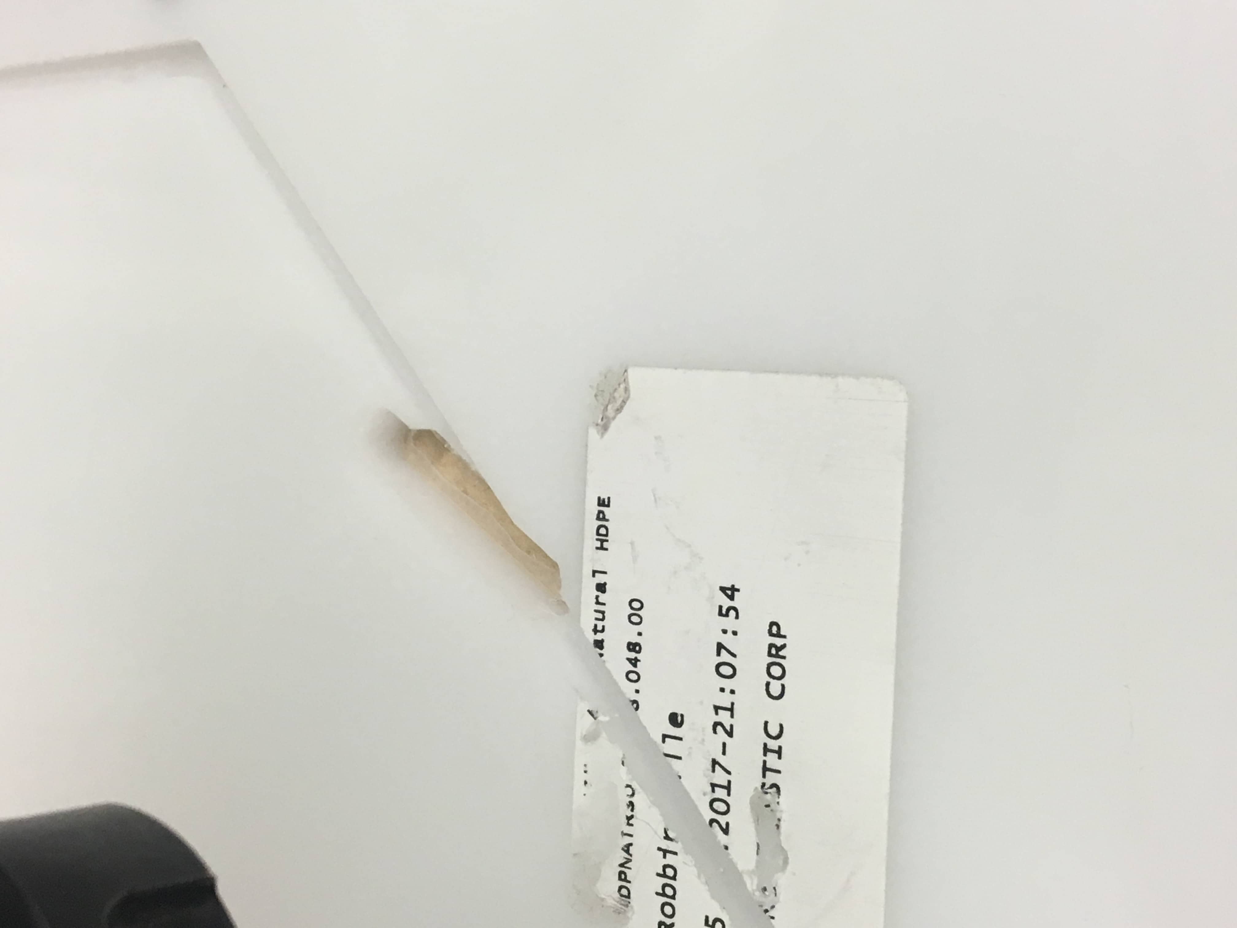
As we were struggling through the redesigning process we decided to start trying to manufacture the pieces we knew were good with the Shark in the EECS lab. This was supposed to be parts 1, 5, and 7 in our design. Part 1 requires the thicker 3/4" Delrin. Parts 5 and 7 are in the thinner 3/8" Delrin.
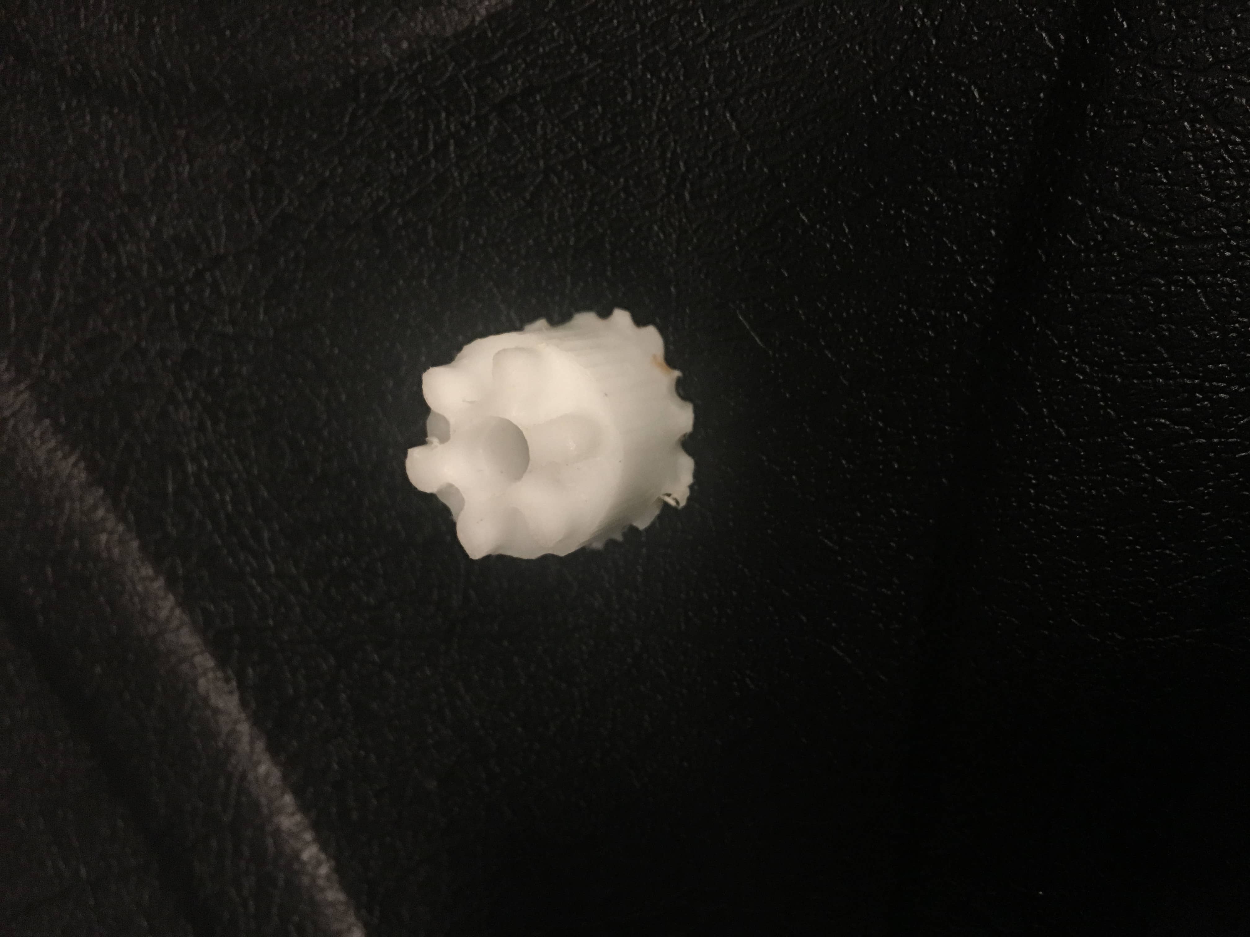
We first started by trying to mill the pinions on the Shark machine. We drilled the block to the bed. We did the rough cut with a 1/8 bit and the finishing cut with a 1/16 bit. The heat deformed the thin wall holding the teeth together and the edges of the teeth themselves. The piece is below and it came out much rougher than when we re-did it later on the Shop Bot. The cuts didn't reach the very bottom of our board - this kept happening in our cuts, even though we set the cut depth to larger than the material thickness. To get the piece out, I had to drill holes around it and then punch it out using a piece of metal and a mallet. That is why the edges around it are unfinished. We considered cutting on the Roland, but decided not to because we didn't think tape would be enough to hold the block down.
Gavin helped us work through setting up toolpaths so we could do it ourselves.
![[toolpaths_ce.jpg]](img/toolpaths_ce.jpg)
![[IMG_8532.jpg]](img/IMG_8532.jpg)
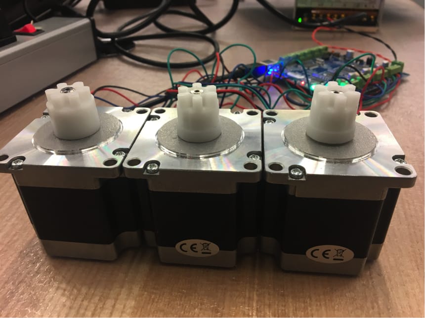
On Monday, we remilled the pinions on the Shop Bot in the architecture shop. To make the tool paths, we got a 2D image of the top profile of the pinion part through Rhino. Then we generated different tool paths for the teeth, the outline, and the outline with the notches (but I don't think the notches add to the functionality so they could be left out). We initially added roughing (with the 1/8 bit) and finishing (with the 1/16 bit) for all of these, but when we milled it, we decided the roughing paths were enough and only ran the finishing for the teeth.
We made some silly mistakes that we realized when we got over to the machine and they wasted time. Luckily we had Robert over in the EDS lab on the (only) computer with V-Carve fixing the files, while we continuously air cut in the architecture lab and relayed the issues to him. One mistake we made was that we zeroed the piece and the bottom of the material. This meant that when we zeroed the z at the top of the material, it cut the air above it and ended right on top. We also had the axis of the bed (x and y) rotated the wrong way. Both of these features are set in Edit > Job Set Up and can be changed easily. Another issue we had was we exported as .crv files when we needed .sbp files.
We didn't mill the outline all the way to the bottom because we were limited by the length of the 1/16 bit. The length from the bottom of the toolholder to the end of the bit was shorter than the total height of the object (and we intended to mill the bottom of the object). For this reason, we didn't mill all the way to the bottom and you can see a ridge towards the bottom of the piece. I think we could've done it with the 1/8 but decided we didn't need to.
There was another weird occurence where the teeth of the first pinion turned out fine, but on the next two, even though we ran the same toolpaths, left pockets of uncut material between the teeth. I would think this would happen if we didn't do the roughing path or if we did it with the smaller bit by accident, but we re-did the path with the right bit and it didn't fix it. We just picked off the pieces and used a filer to smooth it off.
During the milling, the driver position got messed up after we had milled everything and only had the outline left. The x-zero was completely off even though we hit the blue reset button and got rid of the warning. We were extremely demoralized by this, especially since it was 1:30am and we had been really exctied to do the final cut. However, we did not give up! To re-zero the machine, we found the first hole milled on the board and found its corresponding line in the G-Code. Then, we inserted the bit in upside down and carefully repositioned it so that it fit into the hole. To do this we used the "fixed" setting on the positioning system. Then, we set the x and y to the numbers in the G-Code. This method wouldn't be 100% accurate because the G-Code moved the bit in a small circle within the hole but it got very close, within a hundredth of an inch. (Plus, we re-cut the parts later anyway because a chamfer didn't happen during the milling).
When we came in to the lab on Tuesday morning we looked over the pieces that had been printed the previous night and there are a few issues with the current rails that make them unusable at this stage.
Issues:
- Missing a chamfer on one edge of part 3 (only one edge was chamfered)
- Chamfer that was made isn't very smooth
- The grooves are not machined cleanly and cannot support a pinion (part 3)
- The pinions (part 1) do not have holes all the way through them
- All right angles are curved from machining and will not "press-fit" as expected (multiple parts)
- Part 8 is missing holes for parts 9 and 10 to fit
- Missing parts 2, 4-7
![[IMG_8537.jpg]](img/IMG_8537.jpg)
![[IMG_8540.jpg]](img/IMG_8540.jpg)
![[IMG_8538.jpg]](img/IMG_8538.jpg)
On the plus side:
- The rails fit snugly into the wooden base pieces
What needs to be done:
- Clear rails of machine scum
- Smooth chamfer(s) on part 3
- Cut missing parts
- Cut chamfers into rails
- Drill through pinions
- File right angles for press fit
- Drill holes for parts 9 and 10 in part 8
During assembly our manufacturing team learned that when alignment is critical, a machine cut hole for screws is likely preferred to hand drilled holes by nonexperts. We had several issues in aligning parts 4, 5, 6 and 7.
Since the first milling led to pretty bad rails and extra pieces that needed lots of post-processing. Kaspar received the nickname of sandmaster from his hand and foot-based techniques of sanding.
![[kaspar_cleaning.jpg]](img/kaspar_cleaning.jpg)
![[kaspar_sanding.jpg]](img/kaspar_sanding.jpg)
Several holes had to be drilled afterwards. Further drilling was needed with tapping and screwing to assemble the whole system.
![[kaspar_drilling.jpg]](img/kaspar_drilling.jpg)
![[kaspar_drilling2.jpg]](img/kaspar_drilling2.jpg)
![[kaspar_drilling3.jpg]](img/kaspar_drilling3.jpg)
![[kaspar_lines.jpg]](img/kaspar_lines.jpg)
![[kaspar_lines2.jpg]](img/kaspar_lines2.jpg)
The arms team created the logo and extra base + top pieces (and some extra laser-cut pieces instead of the flat pieces that would have been cut in HDPE because of time issues).
![[kaspar_components.jpg]](img/kaspar_components.jpg)
Coding
This Sunday (11/12) the software team is moving along nicely and is within striking range of a finished product. Testing and tuning is of course contingent on having an assembled machine: in particular tuning stepper motor currents and speeds can only be meaningfully done under final assembled load.
- Max worked mainly on the subtask of pulling out paths from SVG files and converting them into lists of world-space points. He's made excellent progress so far and I expect to see his work in mainline branch very soon.
- Vibha has been working on the subtask of writing the coordinate transform. This is in progress and currently has some code in mainline, but is waiting on final measurement of physical parameters and better understanding of a couple of algorithm parameters.
- Ben worked mainly on the conversion of world-space toolpath points to gcode, as well as the main user interface flow and the communication framework between our software and the TinyG. This works beautifully with a test toolpath and is present in mainline, mostly waiting on remaining tasks before integration.
Tasks we still need to do as of Sunday night:
- Configuration of the TinyG for final axis geometry. (How far does each axis travel per stepper revolution? Final axis lengths?)
- Tuning TinyG motion parameters for final assembled load.
- Start-to-finish testing of our proposed CAM workflow.
- Any additional code required by the end effector team.
![[tinyg_alive.jpg]](img/tinyg_alive.jpg)
![[software_running.jpg]](img/software_running.jpg)
Here's a picture of what real coding looks like:
![[IMG_8534.jpg]](img/IMG_8534.jpg)
Arms
First, we looked at the general rail and end effector plate setup and confirmed that we needed effectively 6 arms as three pairs of axes, one pair for each delta axis.
![[joints_ideas.jpg]](img/joints_ideas.jpg)
Furthermore, simple joints would not be sufficient because of the required 3 axes of freedom of the plate and its interaction with the vertical rails. We initially considered variations of universal joints and ball joints. We 3d printed the following joints:
![[joint_ball_socket.jpg]](img/joint_ball_socket.jpg)
![[joint_universal.jpg]](img/joint_universal.jpg)
![[joint_modular.jpg]](img/joint_modular.jpg)
The results were quite imperfect. Only the modular joint was able to rotate, but it was highly uneven. Using a same material for similar parts leads to bad friction, and here we had also poor resolution leading to bad joints. However these are good attempts and we could consider the modular joint as a solution. Another option Jake mentioned was to use a metallic ball which would attach to arms using magnets.
![[joint_3dprint.jpg]](img/joint_3dprint.jpg)
At this point, while waiting for the 3d prints (and then waiting for the support to be dissolved), we decided to explore a simpler idea for the arms. The simpler approach was to use strings, which we would make rigid (for enabling 2d motions within a given Z plane) by using some tubing. Although we could buy tubes or find some rigid tubes in stores, we decided to use what was available in the shop. For the strings, Gavin found us fishing wires as well as some simple fine strings which we could use. For the rigid part, we thought of using laser cutting and potentially have rotated flexures but ended up testing a much simpler alternative consisting of a basic box.
The first attempt was made using acrylic (cardboard would be too flexible). Alex desperately tried to match a good kerf (seemingly larger than with our original cardboard experiments). This was harder than expected because of the very small diameter of our expected tubes (material was 1/8 inch, full outer diameter was three times that). Interestingly, the acrylic sheets would bend up (probably because of the flames from the laser cutting the paper coating), which would be very inconvenient if we had tried to cut several pieces. In fact, one piece didn't get cut correctly because of that bending effect.
![[arm-acrylic.jpg]](img/arm-acrylic.jpg)
![[acrylic_attempts.jpg]](img/acrylic_attempts.jpg)
![[acrylic_bending.jpg]](img/acrylic_bending.jpg)
These attempts were not satisfactory for two reasons: (1) finding a good kerf ending up in tight joints was harder than expected, and (2) the flexibility of the thin acrylic sides would make for a quite elastic tubing.
We ended up using plywood that Elysa brought with her which would provide much nicer friction and for which no complex kerf computation was needed. It had to be cut and after trying with big scissors, Natalie gave up and got trained to use the band saw instead (which went smoothly). It did not bend during cutting, possibly also because we used much larger slots sizes. Locking the pieces together required some tenacity and we got help from others after we all had had dinner for some laugh and to quickly compose our 6+1 tubes made of out a total of 28 slotted plywood rectangles. Interestingly, the pieces twisted after during assembly and ended up having each end rotated by 45 degrees relatively to the other (it may be a bug, or maybe a feature).
![[arm-plywood.jpg]](img/arm-plywood.jpg)
![[bandsaw.jpg]](img/bandsaw.jpg)
![[plywood_help1.jpg]](img/plywood_help1.jpg)
![[plywood_twisting.jpg]](img/plywood_twisting.jpg)
![[plywood_help2.jpg]](img/plywood_help2.jpg)
Finally, we tested putting strings along the tubes. The finer strings were easily pushed through using a heavy needle whereas the fishing one took longer given that pushing would easily have the wire stuck between slots.
![[plywood_strings.jpg]](img/plywood_strings.jpg)
The arms team also created the logo and extra base + top pieces (and some extra laser-cut pieces instead of the flat pieces that would have been cut in HDPE because of time issues).
Sawing the arms in half once we attached the rails to the top and bottom and realized a good size for the arms.
![[img_3511.jpg]](img/img_3511.jpg)
End Effector
Since the end effector can be modular, we will start designing for a pen plotter and move on to more complicated designs (like a claw perhaps) if and when we get a working design. With the end effector we ended up realizing that it was also designed for a right triangle instead of an equilateral triangle.
We don't seem to be getting a working design so pen it is!
Lessons Learned
This is an ambitious project for a week's project. Especially with limited lab hours (EDS technically closes at 2030 though we got them to keep it open late on multiple occasions). We had people working in the lab during all of its open hours from Thursday evening all the way to class time. So we can't really fault ourselves on time management. The problem is instead an excess of ambition, perhaps. And underestimating the time factor of problems in manufacture.
Final Product
Large crowd assembling the pieces together.
![[kaspar_crowd.jpg]](img/kaspar_crowd.jpg)
![[kaspar_crowd2.jpg]](img/kaspar_crowd2.jpg)
Glueing the arm connectors to their holes in the HDPE. Glueing also the arm's endpoints with washers to create smooth endings avoiding the string to be stuck in the plywood components.
![[kaspar_glue.jpg]](img/kaspar_glue.jpg)
![[kaspar_glue2.jpg]](img/kaspar_glue2.jpg)
![[kaspar_glue3.jpg]](img/kaspar_glue3.jpg)
Testing the rails with the board.
![[kaspar_testing.jpg]](img/kaspar_testing.jpg)
Assembly prep. Trying to keep spirits high.
![[20137.jpg]](img/20137.jpg)
Starting out.
![[20619.jpg]](img/20619.jpg)
But the lights kept going out in the lab.
![[20842.jpg]](img/20842.jpg)
We made do and got all of our rails onto the machine.
![[20941.jpg]](img/20941.jpg)
Soldering and heat shrinking to extend the wires coming out of the three mounted motors.
![[img_3514.jpg]](img/img_3514.jpg)
Finally transporting the end machine to be stored somewhere top secret (well, programmed by the late programmers in fact).
![[kaspar_transportation.jpg]](img/kaspar_transportation.jpg)
There is a thing that works.
Go team!
![[img_3517.jpg]](img/img_3517.jpg)
Of course there are improvements that can be made. But we did make a machine that does a thing when you tell it to using a computer.
THE END (for now)