week 12: networking & communications
This week's assignment was to design and build a wired and/or wireless network connecting at least two processors. This was my most successful electronics week so far. Electronics have been a struggle for me this semester. I've been unable to program the vast majority of boards that I create, even after lots of attempts to debug the hardware, and the rc=-1 error is quite discouraging. But this week, I made three boards in one day and all of them worked! Of course, this was preceded by a failed board, but still, I was excited.
I wanted to create a serial bus system of boards, because wired communication between the computer and a few boards will be sufficient for my final project. For my final project, I want a computer application to send signals that turn on and off LED lights embedded in piano keys. So this week I wanted a node board to control LEDs. I designed a board with six charlieplexed LEDs controlled by three pins on an ATTiny44. Eventually, I want to control twelve LEDs and they will be external rather than surface mount LEDs on the PCB, but I figured this was a good starting point. I also created a bridge board in Eagle modeled after Neil's.
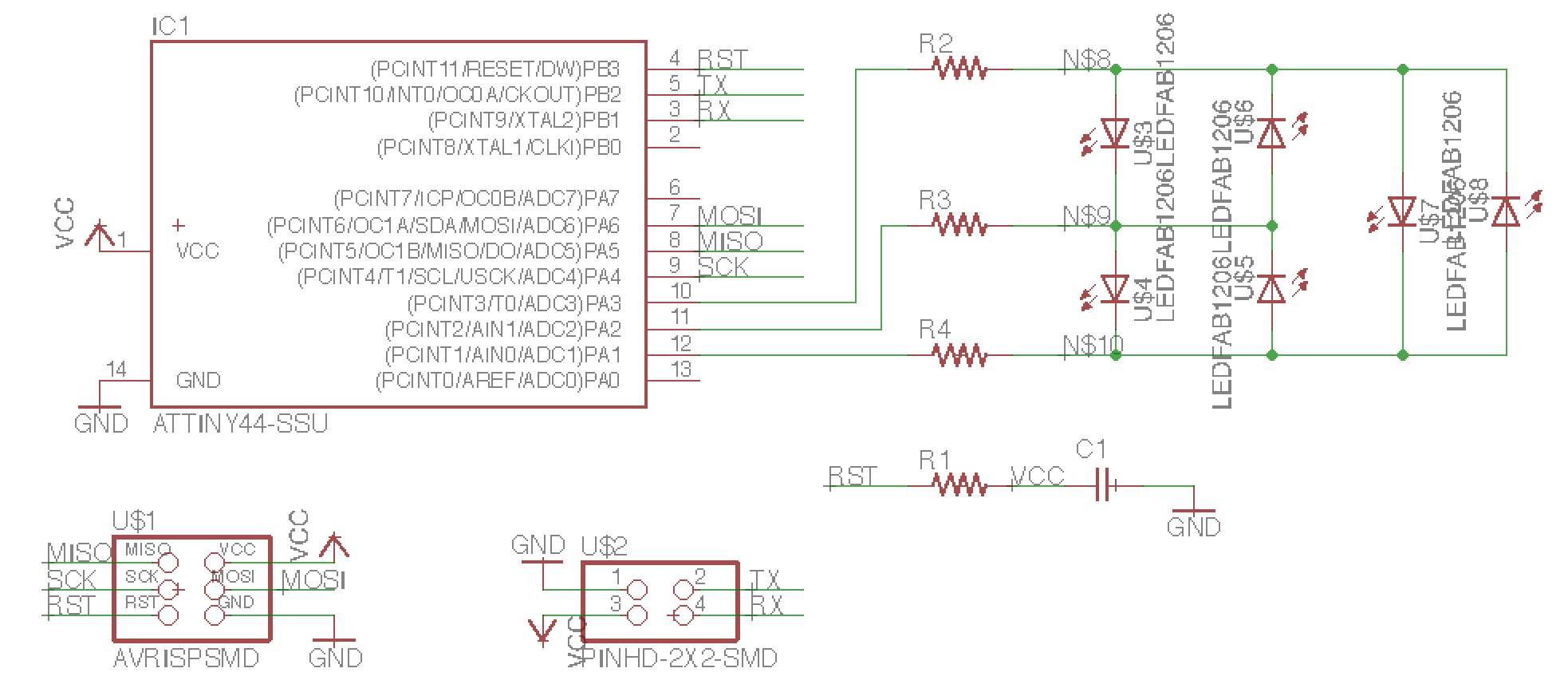
The schematic and layout of my LED charlieplexing node board.
First, I milled the bridge board on the Roland and soldered the parts. The milling didn't come out very clean, and I'm not sure why. When I first connected it to my computer, I got warnings that the device was using too much power and had been disabled. I probed it with a multimeter and noticed that on one edge of the board, Gnd and Vcc traces were completely connected, even though my design had them separated. I took an X-acto and eventually got them separated. This fixed the device using too much power problem. When I tried to program it, I got my favorite rc=-1 error. I probed with the multimeter more and thought one of the ISP header pins might not have been connected. I resoldered that connection, but when I tried to program again I got the same error.
The bridge board after I used an X-acto to fix the short between Gnd and Vcc.
The next day, I decided to remake my bridge board. But instead of milling it on the Roland, I used the Othermill. I'm such a fan of it now. I had used it once a couple weeks ago with Ben's help, but had forgotten the exact steps so I looked at the instructions Ben sent out a while ago which were really helpful. I milled the bridge board and it came out really cleanly and also milled Neil's sample node board.
Milling with the Othermill.
After soldering both boards, I tried to program the bridge to be board 0 and...it worked! It was amazing. Then I tried to program Neil's basic node board to be board 1 and it also worked. I attached two headers to a rainbow cable and connected the two boards together. Then I started screen, and the boards responded to 0's and 1's as expected.
The bridge and basic node responding to their id's.
In the middle of milling, stuffing, and programming my boards, I attempted to help Casey with debugging her interface & application week stuff. The baudrate appeared to be off, so she went to an oscilloscope to try to figure out what was going on and showed me an oscilloscope which was neat. Little did I know I would have to use one later that evening to try to debug my own board.
Learning what an oscilloscope is.
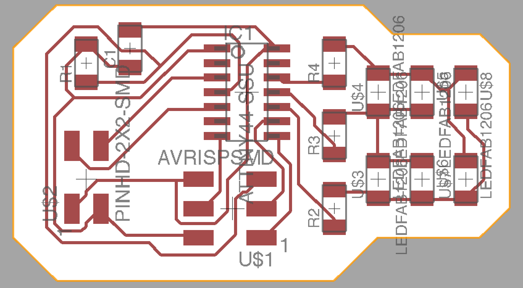
I was feeling a bit more confident having just been able to program two boards, so now I wanted to try my charlieplexing LED node board. I milled it on the Othermill and stuffed it. I referred to a combination of Neil's charlieplexing code and the node code to create a file for this node. I was assigning it id 2 and trying to make a sequence of LEDs light up when the character 2 is received by the board. I connected it through my bridge board, but when I tried to program it I got the dreaded rc=-1 error. A couple weeks ago, I had a problem with one of the programmers not working. So I tried swapping out the programmer for the other one that lives in EDS, and it worked! The three boards I made on the Othermill all came out really cleanly and were able to be programmed, so I think I'm going to stick to the Othermill from now on when I have the choice between it and the Roland.
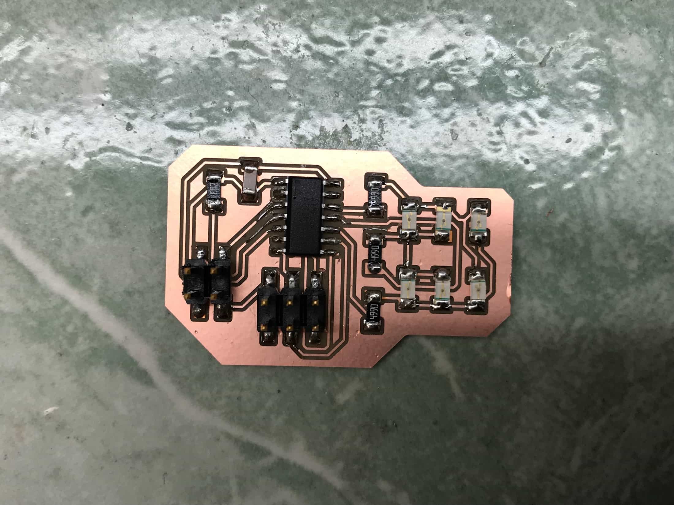
My charlieplexing node board.
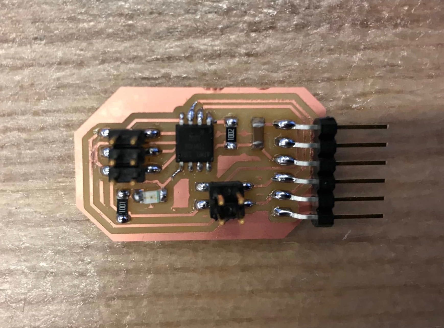
I may have been able to program my charlieplexing node, but it wasn't behaving as I expected. Its LEDs were supposed to flash in sequence when the character 2 was typed, but it was only responding to the character 0. And instead of all six LEDs working, only two ever turned on. The second issue was fairly straightforward to figure out and resolve. The ATTiny pin that was supposed to connect to the bottom resistor wasn't actually connected. Once I resoldered that one joint all six LEDs flashed in sequence like they were supposed to.
I fixed this problem of not all the LEDs working by resoldering one joint.
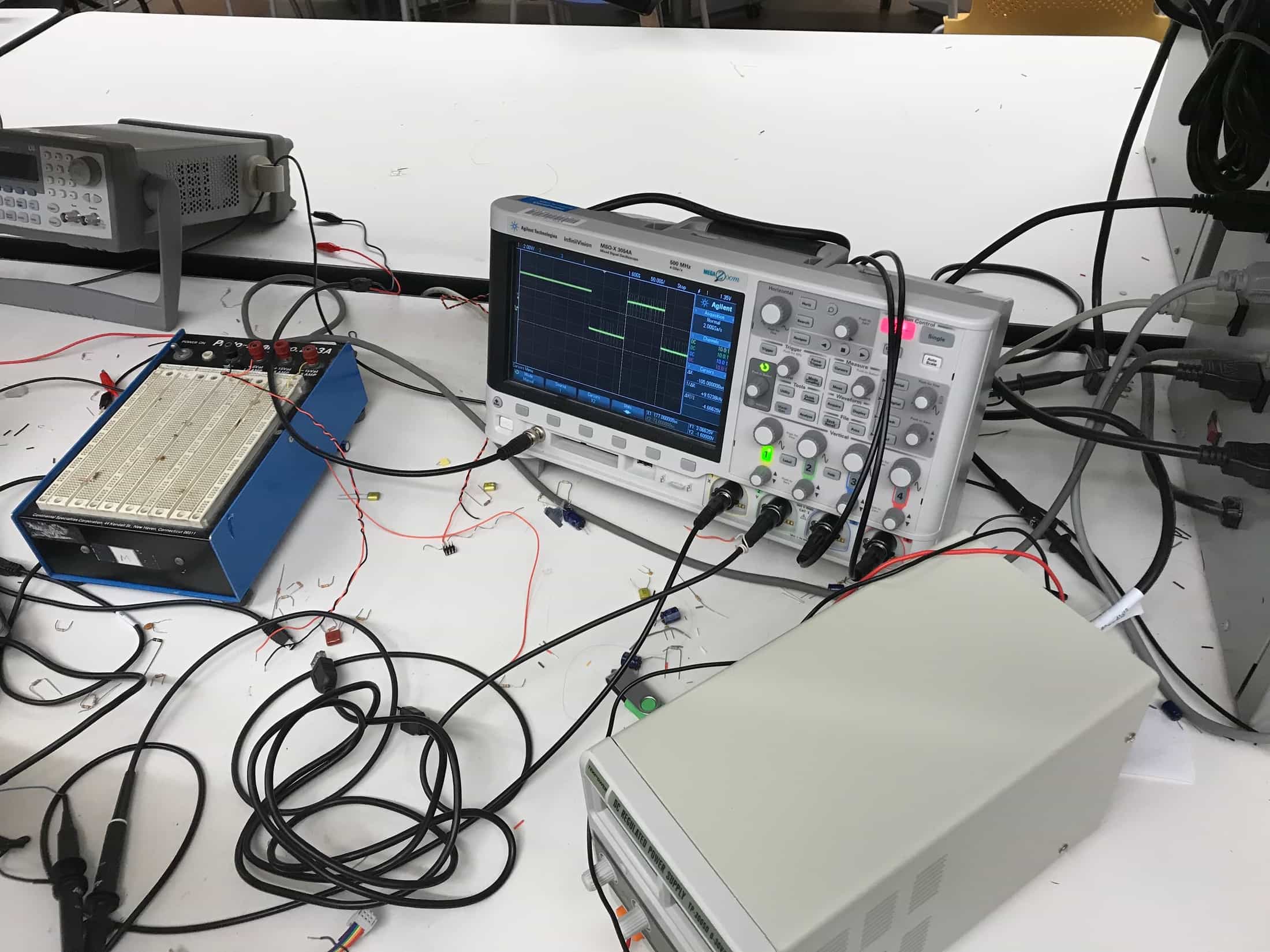
I wasn't sure what was causing the other problem. One LED should have flashed in response to any character input, and the sequence of six LEDs should have happened in response specifically to the character 2. Instead, the flashing sequence was happening only for character 0, and no LED was flashing in response to any character other than a 0. I asked the TA Will for help during his office hours. He wasn't sure what would explain that behavior, and suggested I try testing with an oscilloscope. Casey had showed me an oscilloscope a few hours earlier, but I wasn't very sure how to use it so Will helped me set it up and figure out what to test.
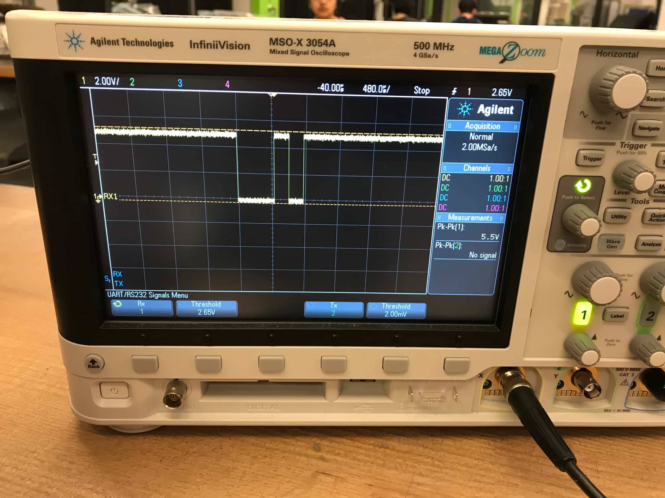
Will helped me use the oscilloscope for testing.
We was that the Tx line on my bridge board would see stuff when any character was pressed, but that wasn't the case for the Tx line on my charlieplexing node board. He thought maybe I had mixed up the orientation of how I connected the bridge to the node, but I checked my Eagle designs and confirmed that that wasn't the problem. It turned out that the problem was that in my code for the charlieplexing node board, I had switched serial_pin_in and serial_pin_out. So my node was receiving from the Rx line. This completely explained the behavior because when the bridge receives a 0 on the Tx line, it echoes back a response on the Rx line. My node was interpreting this response on the Rx line as a transmission from the computer, so one LED flashed when I typed 0. But for any other character, the bridge doesn't echo anything back, so my node never responded to any other character. When I swapped the declarations in my C file and reprogrammed my board, the node responded as it should have. I connected the bridge, the basic node, and my charlieplexed node, and was really excited that everything worked.
Things actually work!
Here is my C file for the charlieplexing node: