Inspiration
I've taken a lot of time lapses during my time. But all of them could be much cooler. After seeing a panoramic time lapse video, I've always wanted a panormic time lapse mount and this was the time to do it.
Paning heads are commercially avaliable in the photo world. One of the top panning heads is noted for being super compact. But unfortunately it doesn't have the speed to do regular panoramics, it's speed made for time lapses. Additionally the head connects directly to the camera to control the shutter of the camera. While I don't think this is possible for the scope of this project, it is something to incorporate in the future.
Overall the goals of this final project was straightforward. Make a panoramic time lapse mount. This should be able to mount to any tripod and be formed to allow any camera to mount to it. The mount needs to rotate a camera, with varying times of rotation that can be dictated by some sort of input.
Electronics
Luckily I did most of the electronic work during the electronic weeks. Follow along to see how I develop the distance/sonar device, the servo output device and networked them together through a serial bus. At the end of networking week, I was able to make a bus connected distance input board and servo output board that once a button is hit on the servo output board, the distance read in will dictate the time it takes for a servo to rotate.
The main change I had to make to the networking code was how the servo rotates. The networking week was designed so the servo rotation time was changed by changing how long the pause between movements was. This created a very jerky video. Instead, I changed the programming so the servo changes every 100ms, but the distance it moves changes based on the distance read in. After reading in the distance, the number of rotations required is calculated. The distance for each servo move is calculated from this number. A for loop moves the dictated number of moves for the calculated amount of distance.
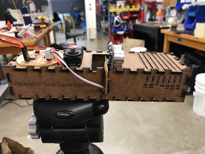
Another change made to the code, is having default settings based on the distance reads. Instead of having the time scale slide to an infinite amount, I used a switch statement to connect certain short distances to 10 seconds, 30 seconds, 1 minute, 5 minutes, 10 minutes, 30 minutes and 60 minute intervals, with 10 seconds being the over default of the device. This allows better planning of how to use the device. This was tuned with the physical housing that was developed later to make sure the slots created in the housing cordinate with the designated times.
Machining
The pieces needed for this final project was a general housing to hold all the boards and provide the distance scale. The second piece needed connects the servo to a mount for cameras. When machining the pieces for the mount, I wanted it to be compact as possible. Unfortunately because input was read in by distance, a decent amount of space was needed create slots for the designated distances. The servo, and thus the camera, was required to be over the head of the tripod for the most possible stability. Having the distance sensor and designated space hanging off the end would make the mount unbalanced. Because of this I decided to place the servo board and distance board and designated space on opposite sides with the servo and camera mount in the middle.
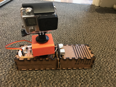
I created the mount between servo and camera by 3D printing it. I made a divit that perfectly fit the servo mount. A 1/4 screw is customary for all camera mounts. While I tried to create my own screw through molding and casting, it broke after I dropped the screw. So I took a 1/4 screw and cut off the head to the appropriate length. Afterwards the servo mount and screw were glued into the 3D printed mount to provide one piece. I had to print two different mounts, since the first one I printed did not have enough stability and was starting to crack. While I know I could have milled this mount, I had already 3D printed the mount and thought it was cool too have 3D printing as part of the project. I created this mount before completing the electronics to test the pieces together. Here is a video of the mount connected to my phone with the legacy rotation code which stops different amounts of time between postitions, creating an unsmooth turn, at three different speeds.
The housing for the boards and servo was more difficult to build. First I constructed a box out of cardboard. This box was to test all the measurements and make sure the device works. This allowed me to designate set distances that correlate to different length time lapses as mentioned above in the electronics section.
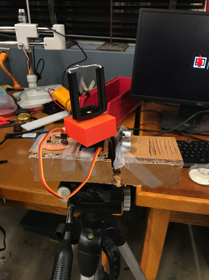
After confirming that the cardboard box works, I designed a press fit box with the correct dimesions. Following Daniel's suggestions I used MakerCase to help me make my press fit box. I used scrap wood from the shop to cut my box out of and the raster setting on the laser cutter to cut some snazzy words. I had copied the distance slots that correspond to rotation time that I calculated on the cardboard box. I glued the pieces together to make the final box. I used the vinyl cutter to cut time indications for each slot for the different distance/time settings of the panoramic time lapse mount. I designed the cut on InDesign so it would perfectly match up with the slots. It took me several tries to properly weed the vinyl and transfer it onto the box. I hot glued a 1/4 nut to the bottom to connect the mount to any possible camera tripod. Additionally I glued both boards and servo in place within the box. The mount between servo and camera was still removeable, to allow better and easier connection to cameras.
Testing
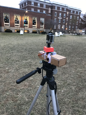
I tested the panoramic time lapse throughout creating the device. For the huge test, I took a time lapse during the sun rise at the Harvard Quad. This was an hour timelapse during golden hour. The shaking is due to a dog running to the tripod. While the sunrise was cloudy and didn't give the huge effect of the sun coming out, the rolling clouds does provide a nice image.
Additionally I tested both phone and GoPro mounts on the device. Below is an iPhone timelapse video taken in the lab.
Unfortuantely I was too afraid to test the mount with my DSLR camera. Since I shoot on a full frame camera, my DSLR weighs over 10 pounds with the lens. While I know the servo has good torque, didn't seem strong enough for my very heavy camera.
Future Steps
There are many steps to improve my project. Making it more compact is a big goal, but would probably need to develop some other type of input device that is not distance. Adding linear movement as well as rotational movement would be really cool. This could build off the concepts we learned during machining week. Additionally, making the mount more stable and powerful to handle full frame DSLR cameras would be very cool.
Bill of Materials
Electronics
- 2 Single Sided Circuit Boards - $2.80
- 1 ATtiny 44 Microcontroller - $1.18
- 1 ATtiny 45 Microcontroller - $1.23
- 1 Resonator 10MHZ - $.43
- 1 FTDI Header - $.1
- 1 5V Regulator - $.34
- 3 6 Pin Headers - $1.80
- 1 4 Pin Headers - $.66
- 1 Button Switch - $.74
- 2 1 OHM Resistor - $.02
- 2 10 OHM Resistor - $.02
- 1 1 uF Capacitor - $.12
- 1 22 uF Capacitor - $.04
- 1 HC-SR04 - $8.99
- 1 HC-SR04 - $8.99
- 1 HKSCM9-5 Servo - 2.99
Machining
- 3D Printed Camera Mount - $4
- Wood Mount - $2.00