IPA, but not India Pale Ale
I've never heard isopropyl alcohol referred to in this way, but I guess there's a reason why I don't drink either type of IPA.

The goal this week was to 3D print something that otherwise could not be made subtractively. I stuggled for a whie trying to figure out what could not be made subtractively. Neil mentioned something you couldn't make on a milling machines or a ball and socket joint as an example. At first I tried designing things with an overhang, but it seemed that you could make those things if you just flipped the piece over on the milling machine and milled again. After experimenting in OnShape for the greater part of Friday, I finally came up with the somewhat simplistic design of the interlocking rings. I know it's still possible to make such model through subtractive methods, but it would be much more complicated. I exported the design as a STL file and saved it onto a USB drive.
I went to the shop, and thankfully both Rob and Lily were there. They explained to me how to use the software that came with Sindoh to size and generate supports for my object. It was very intuitive and easy to use. I ended up scaling my design in half and only using the supports that were directly touching the platform. I saved the g-code, which slices the mesh and translates it into path information for the nozzle and went to the machine. The interface on the machine was really easy to use; just insert the USB, select which object to print, and press play to start. I also appreciated that the machine gave an estimate for how long the print would take (in this case ~40 mins).


While the part was printing, Lily and I attempted to scan our faces with the Sense scanner. For our first attempt, Lily sat on a swivel chair in front of the Sense scanner and spun around slowly. The result was pretty incomplete, so we tried a manually scanning. This worked a bit better, but still had trouble scanning under the jaw and on top of the head. It would pretty consistently lose tracking if we went too quickly. I also tried scanning a smooth rubber duck, but the reflections on the surface seemed to confuse the scanner. As a result I got a really weird bumpy surface.


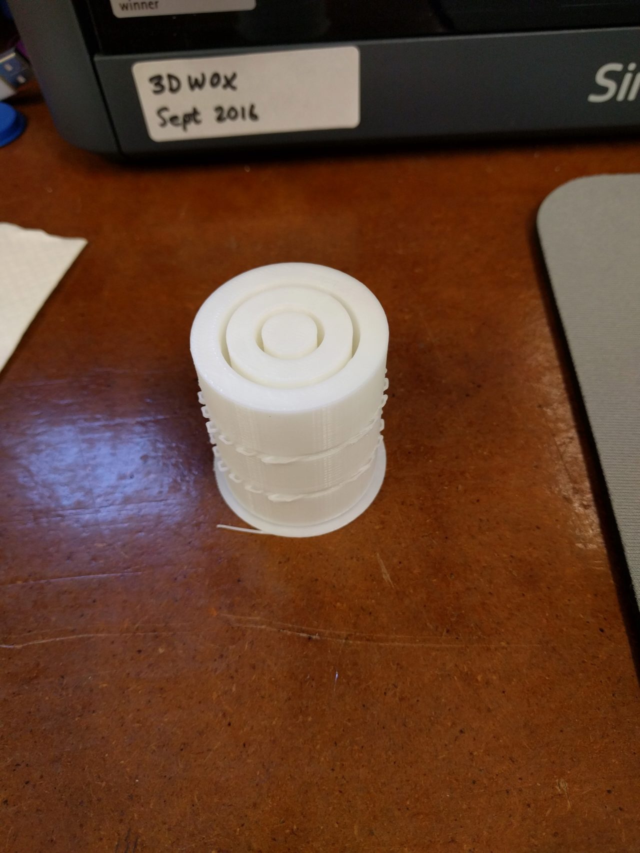
At this point, my 3D print of the interlocking rings had finished. Once the bed had lowered, I pulled the print off of the bed, which was pretty painless because of the painter's tape on the surface of the bed. I later found out how important this was because I had a much harder time trying to remove another print from just the bare surface of the machine bed (a paint scraper was necessary in this case). The supports were actually quite easy to remove, but they did leave a rough surface. Dixon suggested that I apply some lower grit sand paper to the surface which removed most of the sharp edges, but did leave a dusty residue.


I was actually quite impressed with the resolution of the rings from the print. There were a couple of imperfections, primarily close to the top of the rings where the nozzle had to bridge both sides of the rings and where the supports attached. The sanding did a good job of smoothing the ridges and blending them together. Overall, I was quite pleased with the result.


I decided to give scanning another try, this time with an object that had a non-reflective surface. In particular, I chose a small piece of wood from a spare parts bin. I set it up on top of a spinning roller-skate wheel and put down the mat that Rob had suggested. The mat was supposed to help the scanner orient the direction that the object was in. I scanned the piece of wood, and got much better results. I converted the scan to an STL file and scaled it down to 0.5 times the actual size. I printed it on the Sindoh and got pretty good results. The 3D printed part smoothed over some of the edges, but was fairly faithful to the general shape and proportion of the object.


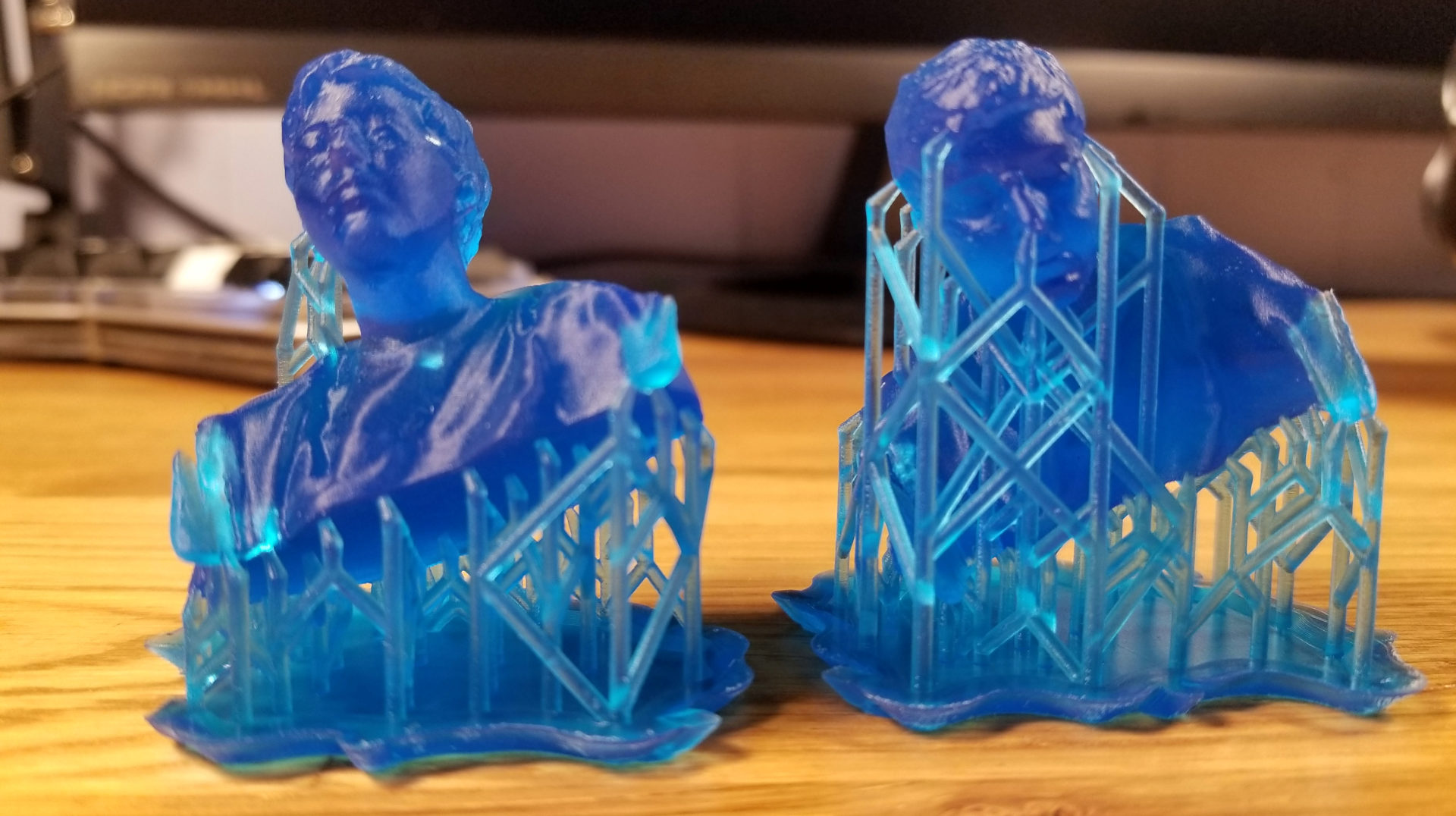
A few days later, Julia said she was interested in the printing something on the resin printer, so we decided to scan her head to see the difference in resolution of the resin printer. We scanned her with the Sense scanner using a combination of the stationary sensor with rotating chair and manually moving the scanner around to catch areas that the first pass had missed. The resulting scan was pretty good! It even managed to catch parts of her glasses. We solidified the scan and used the Preform software to orient the scan in two ways. The automatic orientation put the supports on her face, so we decided to also try manually orienting such that the angle was roughly the same, but that the supports touched the back of the head. From earlier training, we knew that this would take roughly the same amount of time since this is actually stereolithography with the laser hardening thin layers of resin. We were curious whether or not our manual orientation would make it fail. Luckily, it didn't! Dixon helped clean up the uncured resin with isopropyl alcohol before curing it under the UV light. The following is one of Julia's pictures of the final result. Her site has much more detail and cooler pictures of the final result!
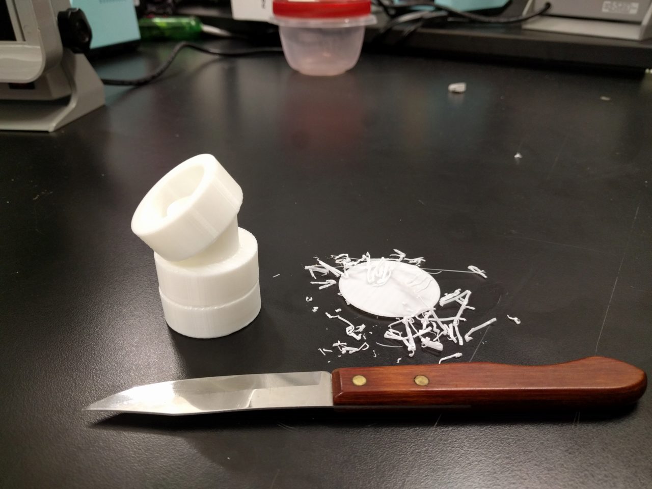
Lastly, I also wanted to try prototyping the spinning mechanism for my maze final project. I used OnShape to create a CAD model for nested axles. I was pretty conservative with how much space to leave in between the axles, in case I needed to add ball bearings later. Using the model, I was able to print the axle as one piece with supports between the layers.

Using a pocket knife, I tried to pry the pieces from the supports. Although it was quite easy to remove the part from the supports beneath it, it was way more difficult to remove the supports from above the part. The surface finish was therefore quite different depending on which side the support was attached on. I'm not exactly sure why the asymmetry exists, but in the future, I will try to design parts that only require supports attached to the baseplate. For this particular design, it probably would have been better if I had just printed the individual parts separately. As an exercise or a proof of concept, I am glad I was able to print this part as one piece.


In the prints that I've made this week, I have seen the limitations of the 3D printer. It seems that the 3D printer is probably best for prototyping, but not for detailed work. The Form2 gave a signifcantly better finish, but took much longer to print. I will keep these considerations in mind as I determine how best to use the 3D printer in the future.
Special thanks to Lily, Julia, Dixon and Rob for their help and insight!