Assignment: Model a possible final project
Idea
For my final project, I am interested in building robots (hopefully more than one) capable of aggregate locomotion. This is based on the locomotion of sawfly larvae (genus Perreyia). I first saw this behavior in a video from Smarter Every Day on YouTube:
The larvae are moving on top of each other, using the layers below them like the moving walkway at an airport to speed up how fast they are moving. Counterintuitively, this leads to the group as a whole moving much faster than any individual could move on its own. In principle, if there are \( n \) layers each with the same number of larvae and each larva is moving with velocity \(v\), the velocity of the group as a whole is . With 3 layers, that 1.5 times as fast as they could move on their own!
This has some really cool implications for collective swarm robotics: it would allow a group of small, slow robots to move much more quickly between locations. For example, if (in some future world) you have a group of robots collectively constructing a skyscraper, they could move between sites on the tower a lot faster and get a lot more work done.
However, it looks like very little research has been done on this approach to aggregate locomotion, both in biological systems and in robotics. I want to build a simple robot that will be capable of this type of movement in two dimensions, including using detected forces between the individuals to stop and start the group’s movement.
Modeling
This week’s assignment is to model our possible final project using a variety of tools. I started with a sketch and worked my way up to a simple CAD model of my robot.
Initial Sketch
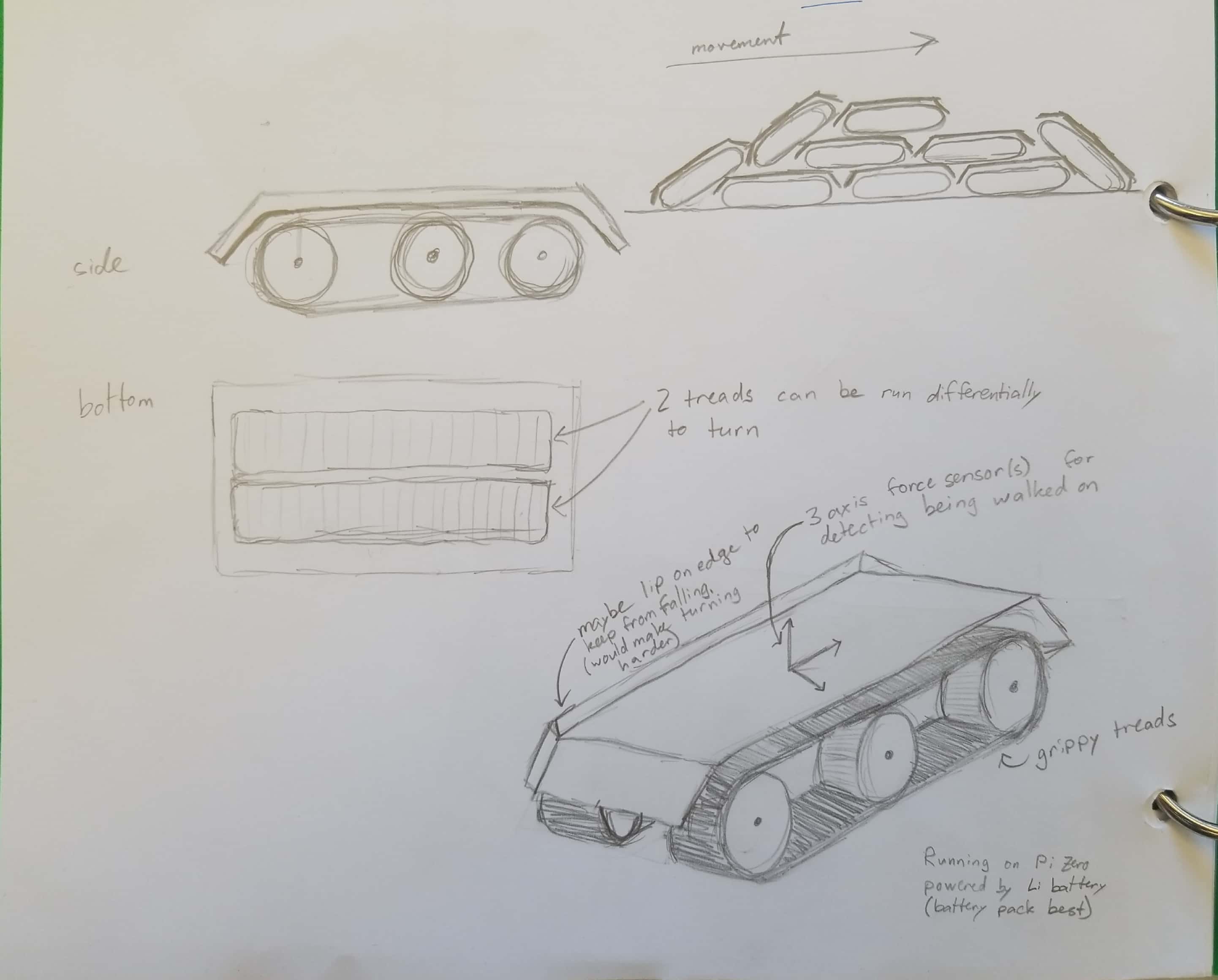
First, I did a quick hand-drawn sketch of the robot. The basic structure is a robot with two sets of grippy tracks for movement, seen most clearly on the bottom right. Having two independently controlled tracks also allows for future changes in control, such as differential drive of the tracks to allow turning of the collective. Over the top of the robot is a smooth (likely plastic) cover with angled or rounded ends that will allow the robots to climb on top of each other like the fly larvae. This top cover will also likely have a lip on the sides to keep the robot from falling off the side of each other. The robot will also incorporate a three-axis force sensor into its cover to detect whether there are robots on top of it (downward force) and whether to robots on top of it are moving (backwards force). The third axis could be used in the future to detect turning. In the top right of this sketch is a side view of what the collective behavior might look like.
2D Render (Inkscape)
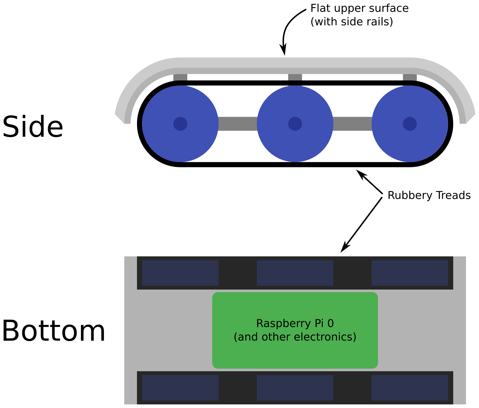
Next, I translated my sketches into a simple Inkscape drawing. Here, it becomes clear that I have incredibly little knowledge of mechanics; I have no idea how the tracks will connected to the upper cover, where the motors will be placed, or how they’ll be coupled to the tracks. But I did leave space in between the tracks for a Raspberry Pi Zero or other electronics to control the robot!
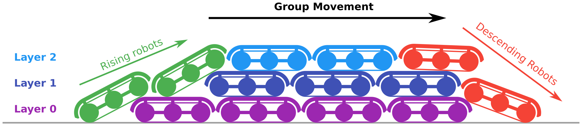
I also made a better diagram of what the collective behavior entails (below). Robots on the bottom/lower layers will be slower (purple robots) and end of becoming “uncovered” at the back of the group, at which point they are unburdened by the robots on top of them and are able to start climbing of the back of the group (green robots). The robots on the top (light blue) use those below them as a moving walkway to reach the front and start descending (red). As they descend, they move slower and are eventually pulled under to the bottom layer.
I have used Inkscape before for more artistic things, but this exposes some of the really big limitations of using it for CAD-type work. It’s not parameterized, so a small change can mean a lot of work. Boolean operations lose the original shape, so you have to undo or start over if you want to make a change.
CAD Model
Next I decided to make a (simple, again) CAD model of the robot. Because I don’t know anything about the gears, motors, or electronics, at this point it is just a 3D version of the simple representation in my sketches. I had never used any 3D modeling software before, so this was a completely new experience to me. I opted to start with OnShape because it’s free for students, works on my choice of computer (Linux desktops and a Chromebook), and is developed enough to have good forums and tutorial videos for a CAD beginner. I was intimidated by CAD software before without having ever tried it, but it’s not as bad to get started as I expected.
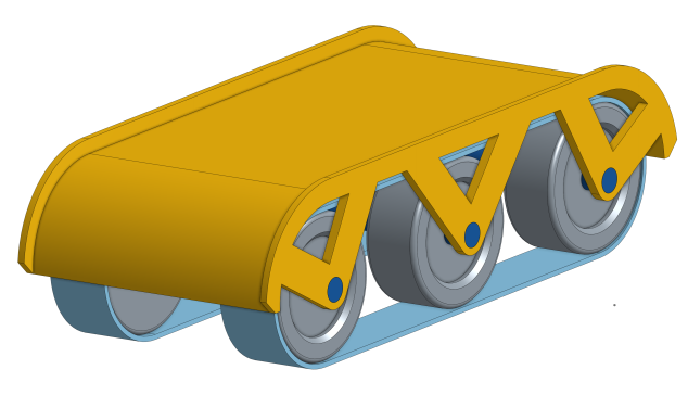
My assembly contains three main parts: a cover with struts to connect to the axles, guides for the track, and the track itself. In reality, the track would be circular and be stretched around the track guides, but I’m not sure if/how that’s possible in CAD software. There are other obvious serious issues with this: the track guides have no connection to the tracks, the tracks have no tread, there’s nothing to hold the axels in place, and there’s no way for any motors/electronics to be connected.
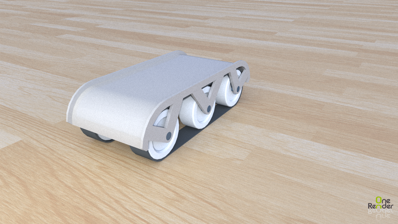
I also played around with a couple ways to output the model. I tested out OneRender, one of the online cloud rendering apps connected to OnShape. I was a somewhat disappointed with the results - the final image is grainy and low resolution, and its attempt at materials isn’t great. In the future, I’ll try exporting to Blender and using its materials and rendering system on my own computer.
OnShape also has the ability to create drawings of parts and assemblies, so I made a drawing of my assembly. It looks a heck of a lot better than my initial sketch on paper.
Future Modeling
To test the principle of whether or not this treadmill robot locomotion will actually work, I would like to simulate the behavior with simple physics. However, I’m not sure yet what would be the best software tool for this. With lots of contact points, I’m concerned that rigid body simulators/game engines might have trouble.