Assignment: Design and print an object that could not be made subtractively. 3D scan an object (and optionally print it).
3D Printing: Extrusion
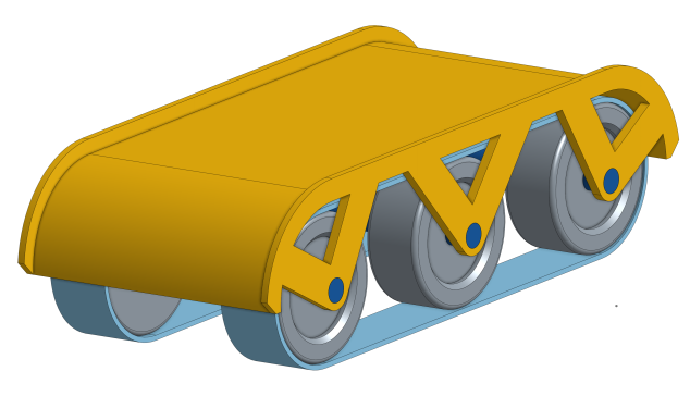
For my first foray into 3D printing, I decided to finally make some progress on my project. I started with the initial design I made for my robot’s cover (see more in Week 1). I used the Sindoh 3Dwox printer for this part. It’s an early prototype that doesn’t have fine features, so this extrusion approach seemed plenty precise enough.
The setup process for printing was incredibly simple. I exported an STL file from my OnShape parts studio and imported it into the printer’s software on the lab computer. I rotated the part upside down to reduce the amount of support material required, selected “supports everywhere” in the settings, and let the software generate the gcode file for the printer. Because the extrusion can support some overhang (45º or steeper, from my observations), it was interesting to see how it only needed supports for the lowest part of the circular curves on the ends. I left the rest of the settings at their default for my first go.
I made this full size to get a sense of how big my robot will end up being (about 13 cm long). However, that did mean the piece took 4:41 minutes to print. (Though I do really appreciate that it gives you a time estimate from the start.) Once I started it, I realized that 17% of printing time was printing a large “raft” underneath of the entire piece, which was probably unnecessary, taking a lot of time and material. In the future, I’ll try changing that setting. Given how long it took, I left it and came back after I was finished. In the meantime, though, Dixon thought the part looked cool when it was finished and took off all the support material when it was finished to check it out. So I didn’t get a chance to see what it looked like at that stage or find out how easy it was to remove the support from the large flat part.
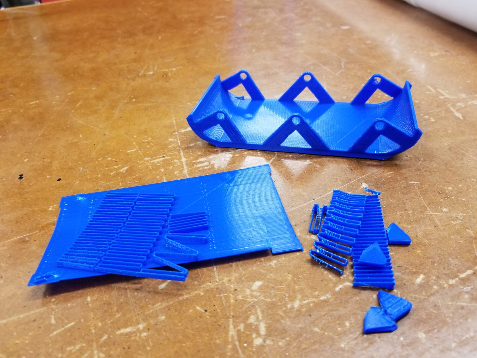
There was quite a bit of support material, but it was mostly the raft for the base, plus for the space between the top surface and the lip of the cover. It also required supports for the struts on the ends but not the middle; the angles for the middle supports were exactly 45º. For the next round, I can change the angle of those outside supports to also be 45º and avoid the need for supports in that space.
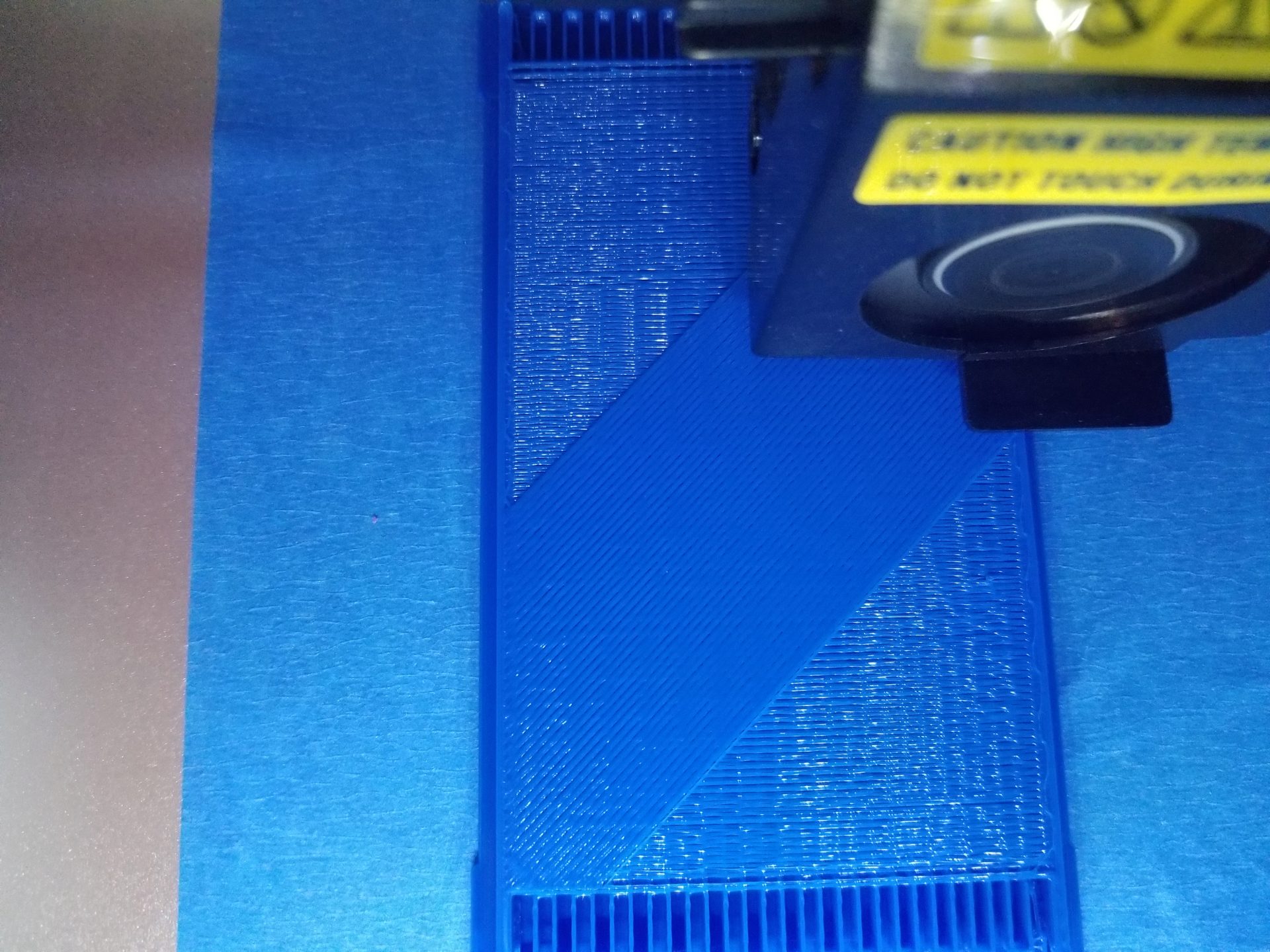
The limited resolution of the extruded PLA is also pretty visible on it. I probably couldn’t have made features any finer than I did with this printer.
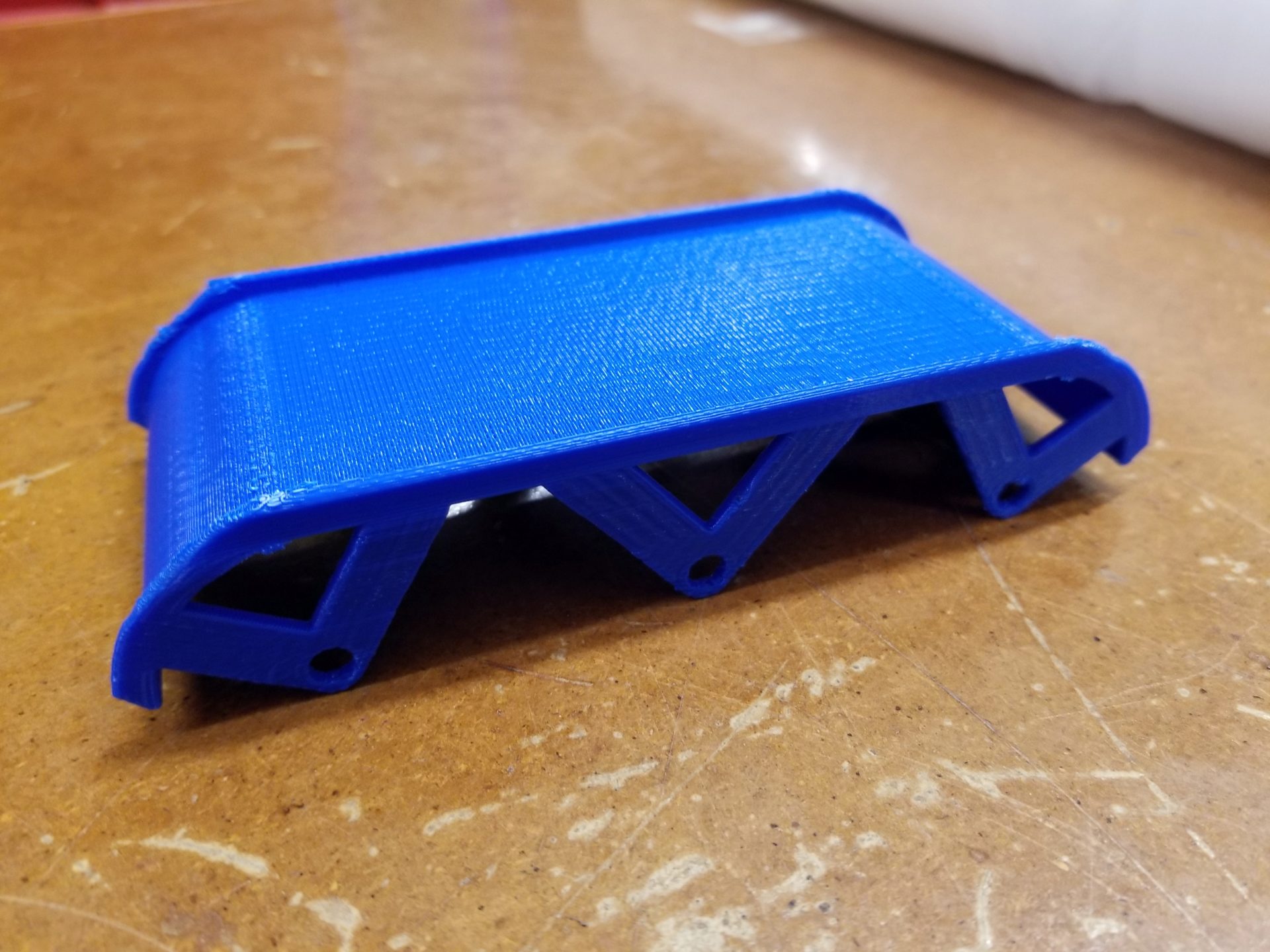
Overall, though, the part turned out really well: no wierd collapses due to lack of support, no major distortion, no places that broke through. It’s pretty cool to actually see the part I designed on a computer screen as a physical object. And there are some things about it you can’t really get a sense of from the screen. For example, it’s narrower than I expected from the screen, I’m guessing from perspective distortion. I’ll probably have to make the whole thing bigger (at least wider) to fit everything I’ll need between the treads on the bottom - motors and electronics.
I’m guessing that I’ll have to do more prototypes of this part as well to figure out what shape to make the ends. At this point, I’m guessing that the quarter circle may be too steep for the robots to climb up. I may end up making the robot asymmetric, with a gentler slope on the back to make them easier to climb, but a steeper slope in the front to help robots get pulled under the bottom layer in the front.
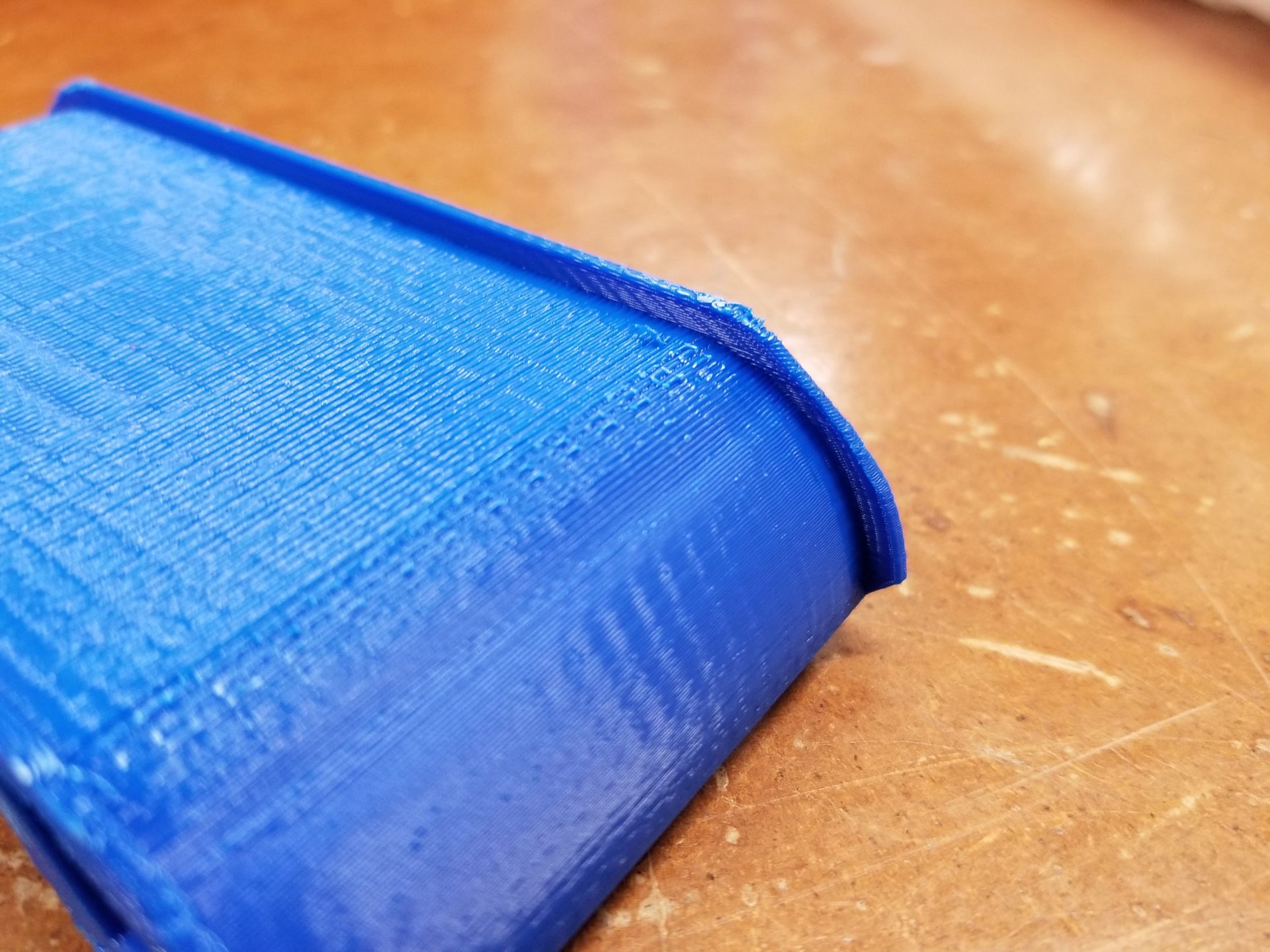
Because I printed it upside down, I ended up with a nice smooth surface on the bottom of my part instead of the top. I think this is because there’s a little bit of sagging and stretching on the first layer that goes down over the support material. In my case, however, this might not be a bad thing: I want the top surface to be as grippy as possible for the robots to be able to climb on top of each other.
The lip on the sides is also smaller than I expected and likely wouldn’t do much to stop the robots from driving off the side of each other. On my next prototype, I’ll make the lip & strut thicker and also make the lip taller.
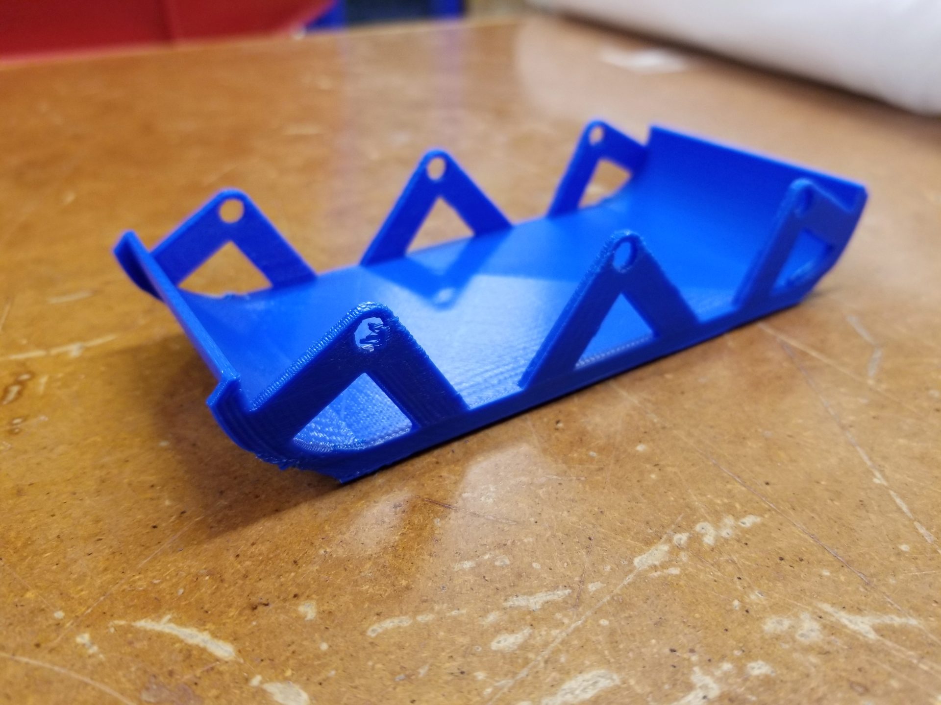
The other interesting part was the holes for the axles. First, they ended up with some support material stuck in them. Not really sure how to get around that, but maybe having the part thicker will help. Second, the distance between the hole and the edge of the strut is really thin. Next time I think I’ll make the struts wider and maybe move the hole a little higher within the strut.
3D Scanning
For the 3D scanning, I got help from Chastity Li to scan my head. We used the hand-held Intel RealSense 3D scanner in the lab and its built-in software, so we didn’t have to do any post-processing of the scan ourselves. It did turn out to be tricky to get a scan of all of me, particularly the top of my head. On our first go, I accidentally held my hands up before the scan was finished and ended up looking like a terrifying creature with my hands fused to my face.
Here’s what ended up working best. I sat in a spinning chair centered in front of the camera mounted on a tripod and slowly spun myself around, trying to move my head and upper body as little as possible. After one spin around, Chastity held the camera higher and angled it down at my head while I spun around again.
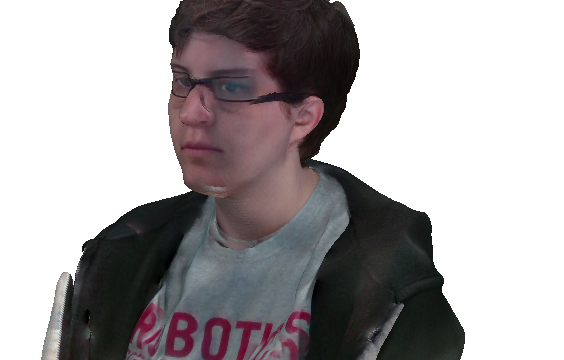
This final image on left looks a little creepy with the texture attempting to overlay, but it actually turned out really well. There were no “holes” and it even got the texture of my hair. This seems to work better with short hair than long hair, which moves more and doesn’t seem to always scan as solid. Interestingly, it also seems that my glasses were too thin do be picked up by the scanner, and the IR went right through the lenses, so my glasses barely show up at all on the scan. You can make out a little bit of a ridge on my temples and the bridge of my nose, but that’s about it.
The other spot it looks a bit funny is the zippered edge of my sweatshirt. I’m guessing that the fabric moved around as I was spinning and created some uncertainty in the model, so in the final object it looks like my sweatshirt really sticks out.
3D Printing: Resin-based
I also wanted to try out the resin-based printer this week to learn as many tools as possible. Also, why would I not want a tiny high-resolution plastic version of myself to put on my desk? We have a Formlabs Form 2 printer in the lab, which uses stereolithography to print parts out or resin. This printer was a little more intimidating, with the prospect of changing resin tanks and post-processing the part. So I stuck with the resin that was already in the printer, which was the translucent blue “tough” resin.
When I imported my head into the Formlabs software, I scaled it way down to about 4 cm wide. When I selected the auto-orientation of the part, it rotated it and added supports right on the front of my face – not ideal. I decided to see how much of an effect the orientation had on the final product, so I ended up putting two parts into the print. In addition to the auto-oriented head, I oriented one myself and the opposite angle so the supports were less visibly located on the back of the head.
Chastity had heard tell that it’s possible to print to the Formlabs printer with a USB drive, but we couldn’t figure that out. It also turns out that the Formlabs software only runs on Windows and Mac, so Chastity helpfully supplied her computer to send my part to the printer. Once the object was configured, all I had to do was hit “print” within the program and confirm on the printer touchscreen.
The startup for the printer was rather slow, heating up the resin to 30ºC. After that, each of the 506 layers of my print was also rather slow. From the side, I could see the light moving around within the resin, but then there was an extended period of waiting, fully lifting the part out of the resin, then putting it back down and waiting for the resin to self-level. I’m not entirely certain what all the steps are for. I went with the fastest setting for the print with layers 100 microns thick, but the print still took 4:40. I stuck around for the early part of the printing, but it didn’t look like much; I left before I could see my part emerging from the goo.
I ran this print in parallel with my other one, so I came back when they were both finished. In the meantime, Dixon had also kindly taken my part out and cleaned the platform. When I arrived, my part was bathing in isopropyl alcohol to dissolve away any uncured resin. I don’t know how long it spent in the alcohol bath, but I stuck it under the UV light for a few minutes to help it finish curing. I probably should have let it stay longer, but at that point I was getting hungry for dinner and took it home with me to show my roommates. Rob said that natural UV light would help cure any remaining stickiness, so this wasn’t too big of a deal. By the next morning, they seemed completely fine.
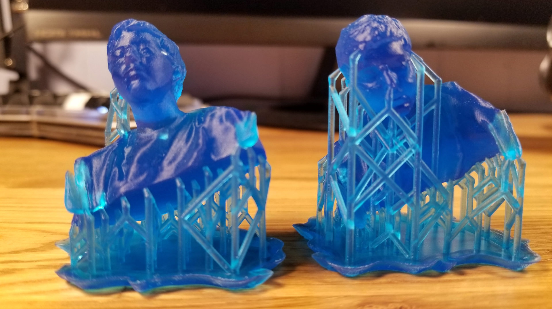
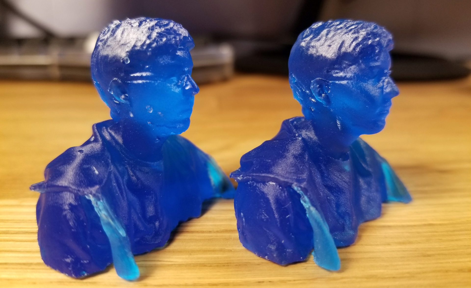
Both orientations of the head came out really well. Here they are still attached to their supports. It looks a little like the Matrix or a cyborg, particularly with that support into my right nostril. I ended up removing the supports with gentle force by hand instead of an exacto knife because I was afraid of accidentally stabbing my model self in the head.
It’s hard to photograph the features of a translucent model, but in real life it looks really good. There’s texture to the hair and the draping fabric of the hood in the back looks really cool. You can also make out the faint impression of my glasses on the side of the head. Those extended flapping jacket zippers I mentioned in the scanning section definitely stand out, but it’s not too visible. Besides, people are going to be mostly looking at my face anyway, right?
This picture shows the difference between the two orientations of the print. The support attachments on the left are rather visible, making it look like I have pretty bad acne. In this default orientation, the face looks a little glossier; these layers were on the top of the print as it was pulled out of the resin. You’d only be able to tell by having them side by side, though; the difference is minimal and neither looks distorted.
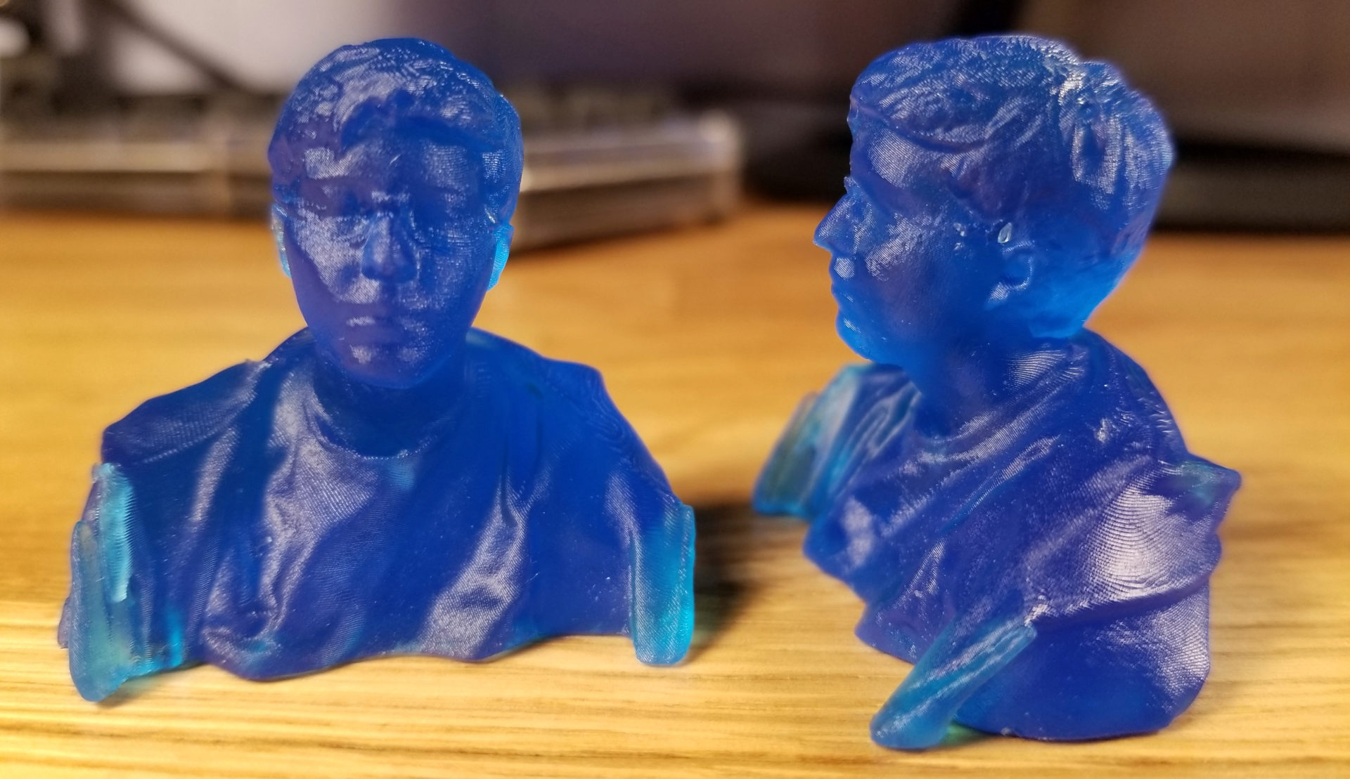
You can see the layers if you’re close, but they’re not so large that it makes the features get lost. Especially on a larger part, this would be fine. If I wanted to get really fine details, I could go with a slower, more precise setting. I did 100 micron layers, but it can go down to 25 microns if you really need precision. My head isn’t that special, though, and it would have taken way longer.
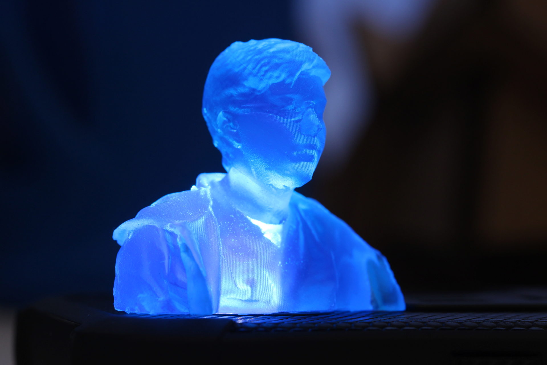
Bonus pic: If I put an LED under the head, it looks like a hologram from Star Wars.
My labmates were really excited by my head print, and one of them immediately suggested that we make a lab Mount Rushmore with all of our faces. We have Agisoft in the lab, as well as multiple RGB-D cameras, so that will likely be a fun side project at some point in the future to learn how to manipulate and combine object models.