Assignment: Add an output device to a microcontroller board you’ve designed and program it to do something.
Design
I’m building a robot, so I really need to make that robot move. That means this week I’m going to make a board to control some regular old DC motors. If all goes as planned, I hope to make a board that will control two motors, like I plan to have on my robot. This week I’d also like to try making a 1.5-sided PCB – in other words, using the other side of my PCB as a ground plane. I need to figure out how to do that in Eagle, then learn how to connect the vias when I build the board.
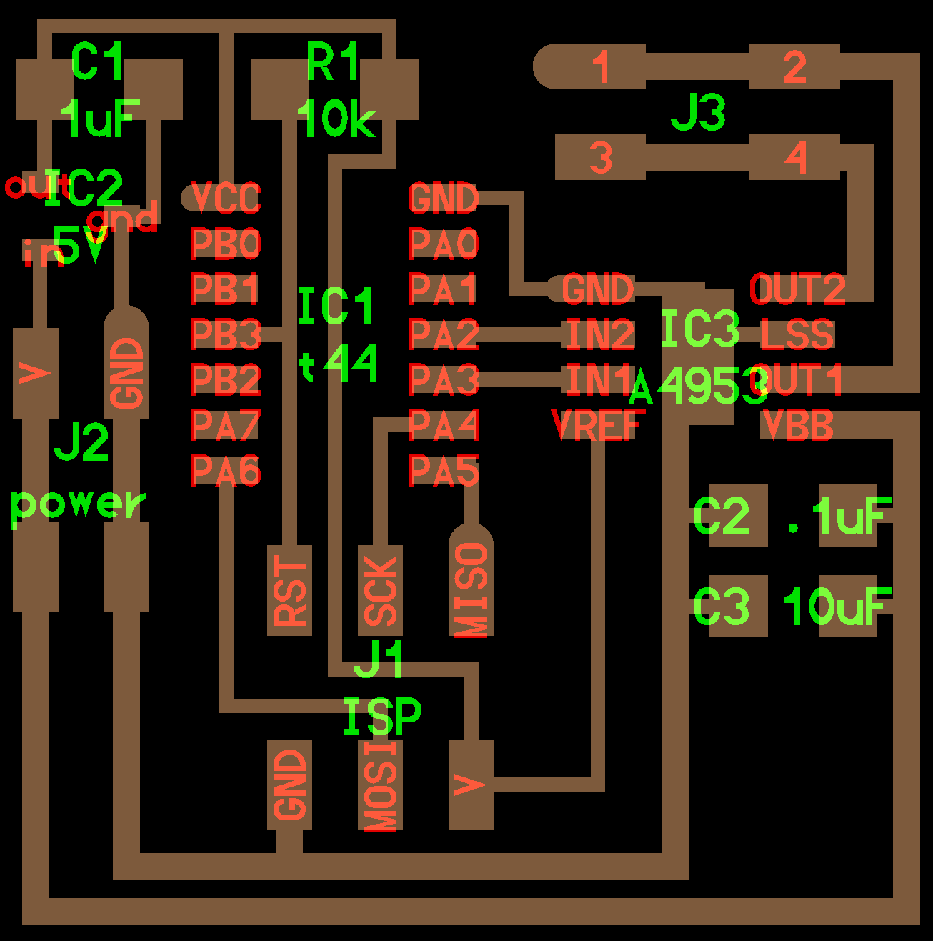
I’m starting with the motor hello world board from the class website. I’ll re-build it in Eagle, add outputs for a second motor, and maybe buttons to control the motor. (This time maybe I’ll even hardware debounce them and save myself a struggle in code.)
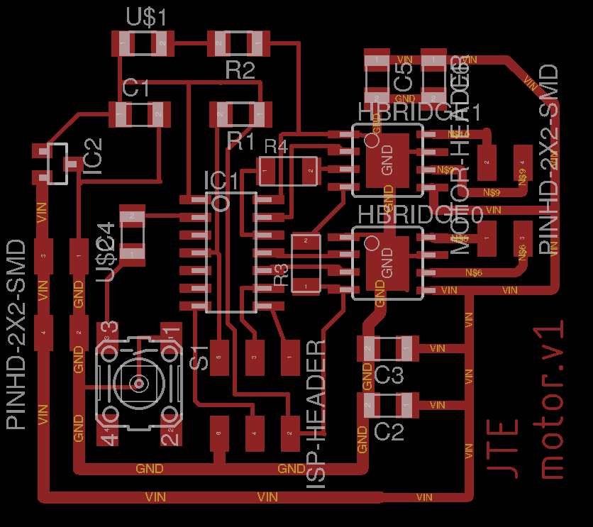
Once I started designing in Eagle, it turns out that adding a second h-bridge makes the layout and routing a lot trickier. I ended up using two 0 Ohm resistors to jump some other traces to get the reference voltage to my second h-bridge. Yuval pointed out something useful to me, though, that let me avoid the 1.5-sided approach. The design in Neil’s routes the power and ground generally in a ring around the outside, and then components inside can draw from that. That turned out to be useful in laying out my board. Also useful: this time I did my schematic by labeling nets instead of drawing a million lines. This turned out to be crazy helpful, because then when I started a trace on the board, Eagle highlighted all the possible pads and traces for it to properly connect to. It also meant it was a lot easier to keep track of my pins on the 6-pin header and the ATtiny.

Milling & Stuffing
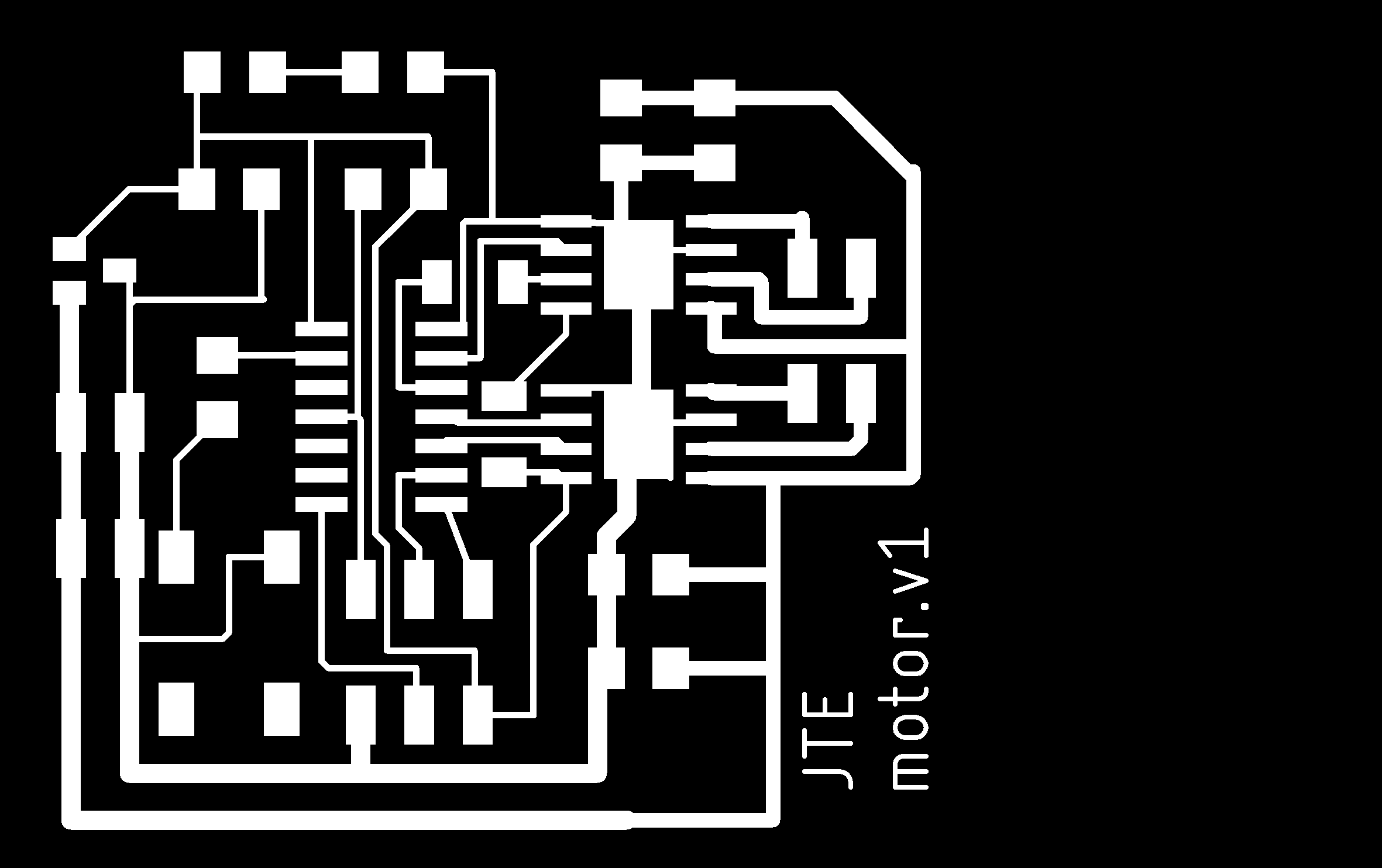
This week I had my first experience with not leaving enough space between my traces. (I should really figure out how to set up design rules in Eagle.) I realized this when I checked the preview in Mods, but it looked like only one or two tight spots, so I decided to go ahead and mill it anyway, then cut those with an exacto knife afterwards.
When it came time to mill the outline, I discovered that the Mods preview didn’t show cutting the bottom edge of the board. It turns out this was because I drew the dimensions of my board in Eagle too close to the workspace boundary. I’d already milled the traces at this point, so I didn’t really want to go back to redo things in Eagle. With a PNG at 1000 pixels per inch and an endmill diameter of 0.03125” (1/32”), I guessed I needed at least 32 black pixels at the bottom of my image for Mods to mill the bottom edge. So I just pulled up Gimp and added an extra 20 pixels to the bottom of my image. I figured I had enough leeway on the bottom to not cause any problems, and I was right.
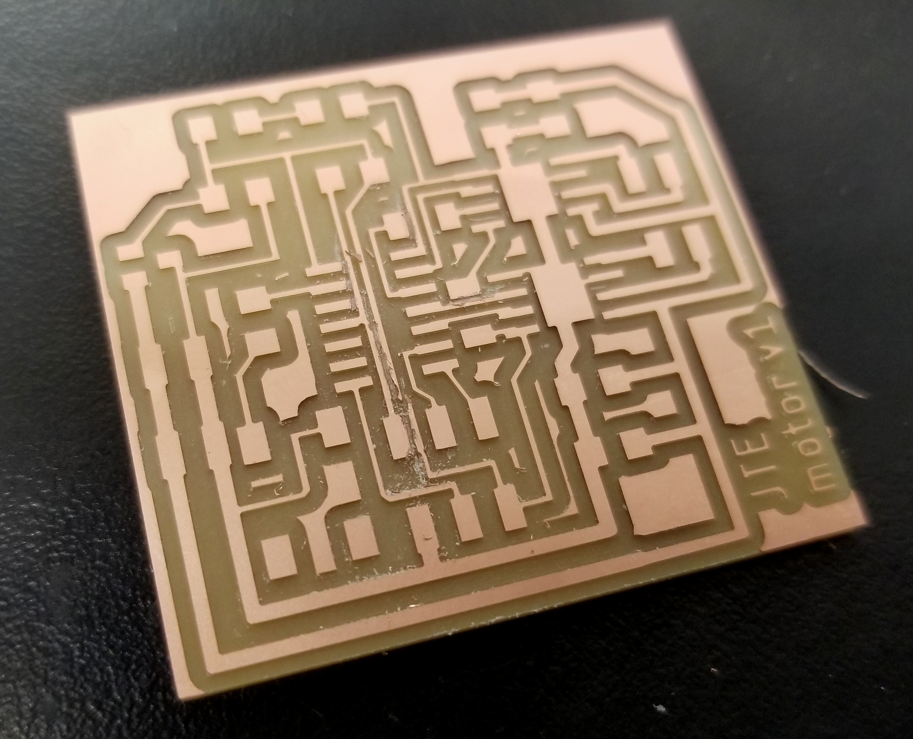
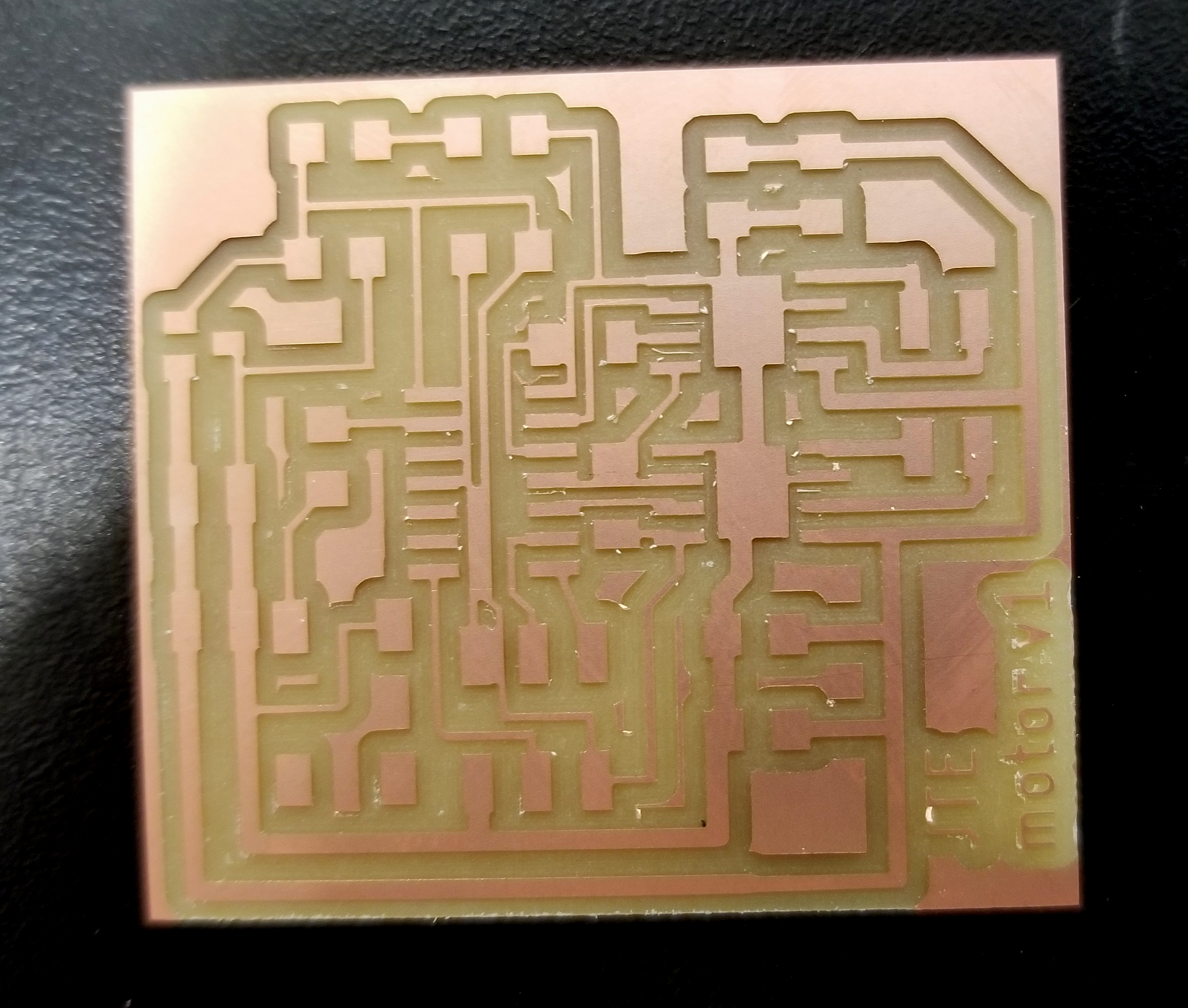
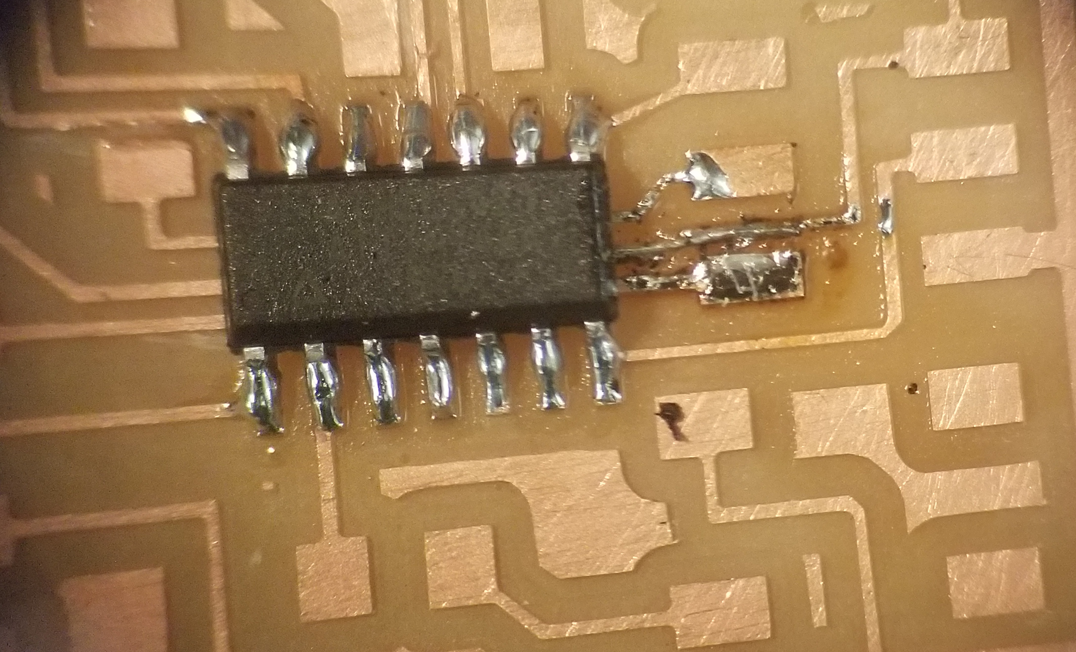
But it turned out I actually had seven shorts that I needed to cut with an exacto knife. In the process of fixing my board, I also accidentally cut through one of my other traces. Crap. Solder had too much surface tension to just create a jumper with that. I tried soldering a small wire, but that was too big, especially in these tight quarters. I ended up pulling a single thin copper wire out of a wire, and trying a dozen times under a microscope before finally getting it to attach on both ends and not accidentally connect to the neighboring trace. It was a huge time sink, but eventually it worked, and I verified with a multimeter that it only connected where was supposed to.
Adding the rest of my parts, I discovered that I’d used the wrong piece for a power jack. But 1 2x2 jumper fit on that spot, so I just used that instead. Besides those delays, stuffing the board went pretty quickly; I’m getting faster at this.
Debugging
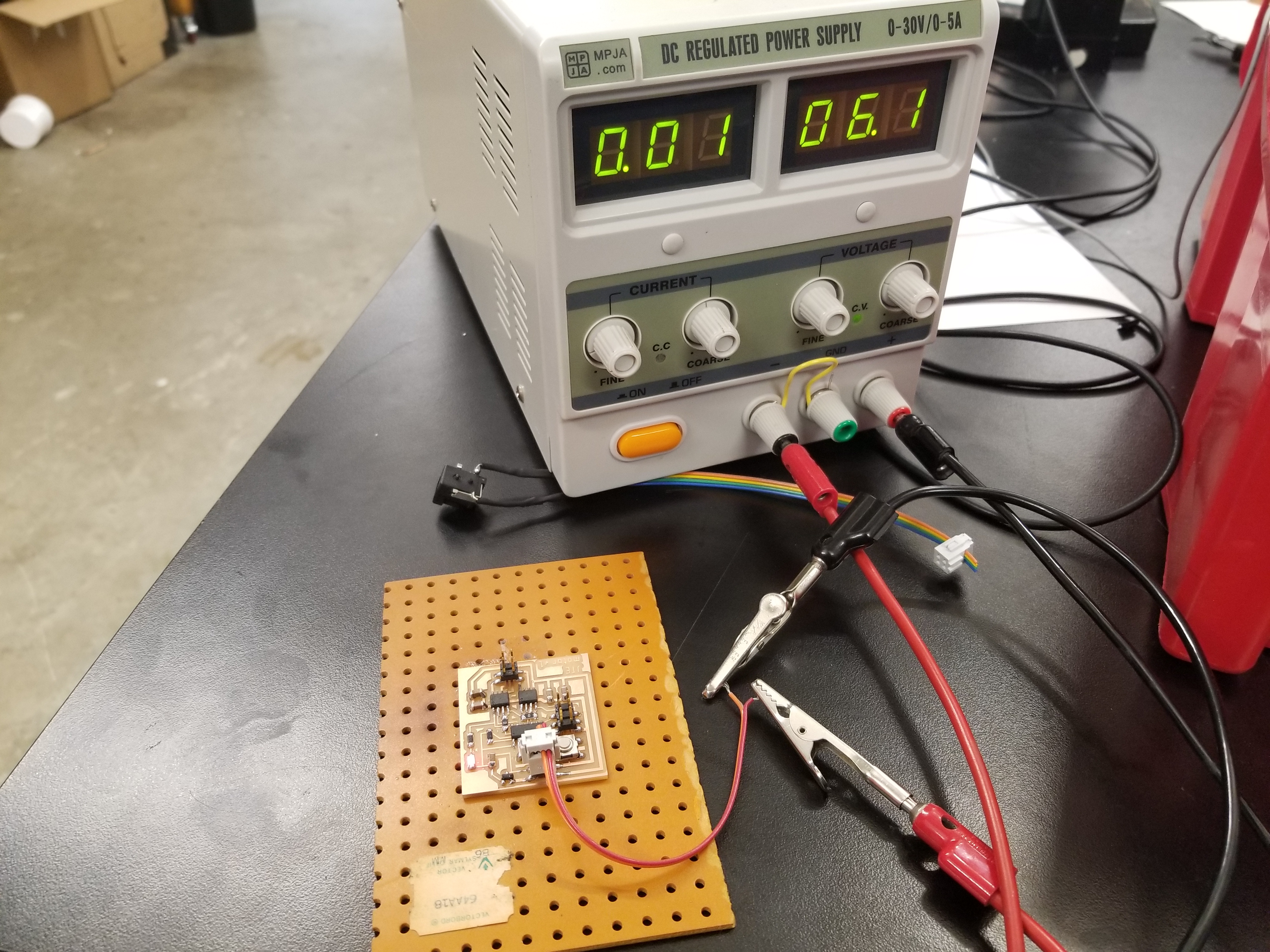
First step: powering the board. I’m glad I added that power LED, since with the 4-pin header for power it’s easy to attach it the wrong way (which, despite my best efforts, I did on many occasions. It doesn’t seem to have killed my board yet.) I started by connecting it to a lab power supply, and it worked, drawing 0.01 A with no motors connected.
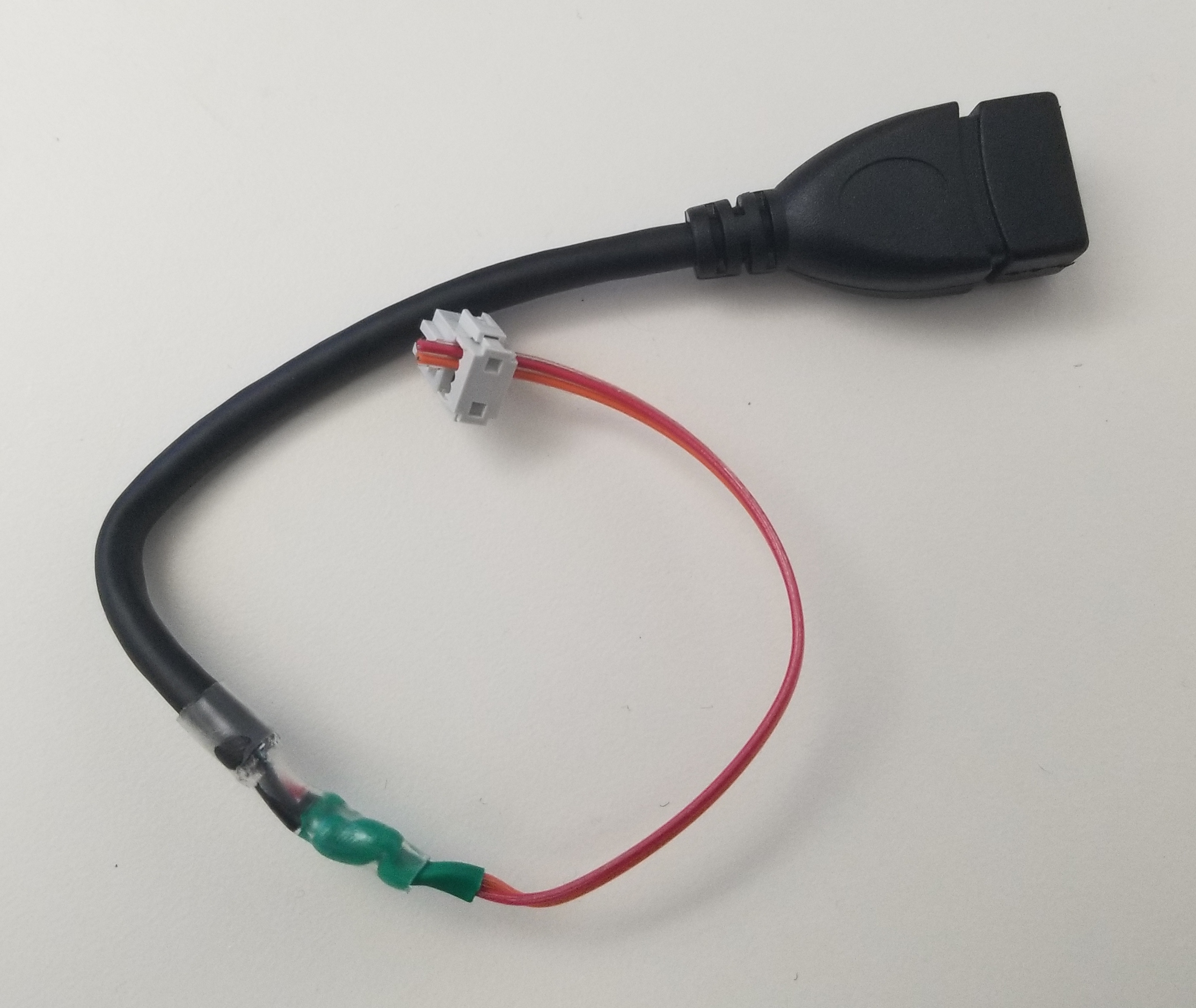
I was on a roll with this whole power thing, so I took the remains of a cannibalized USB power cord from my lab and connected it to a header cable to power my board.
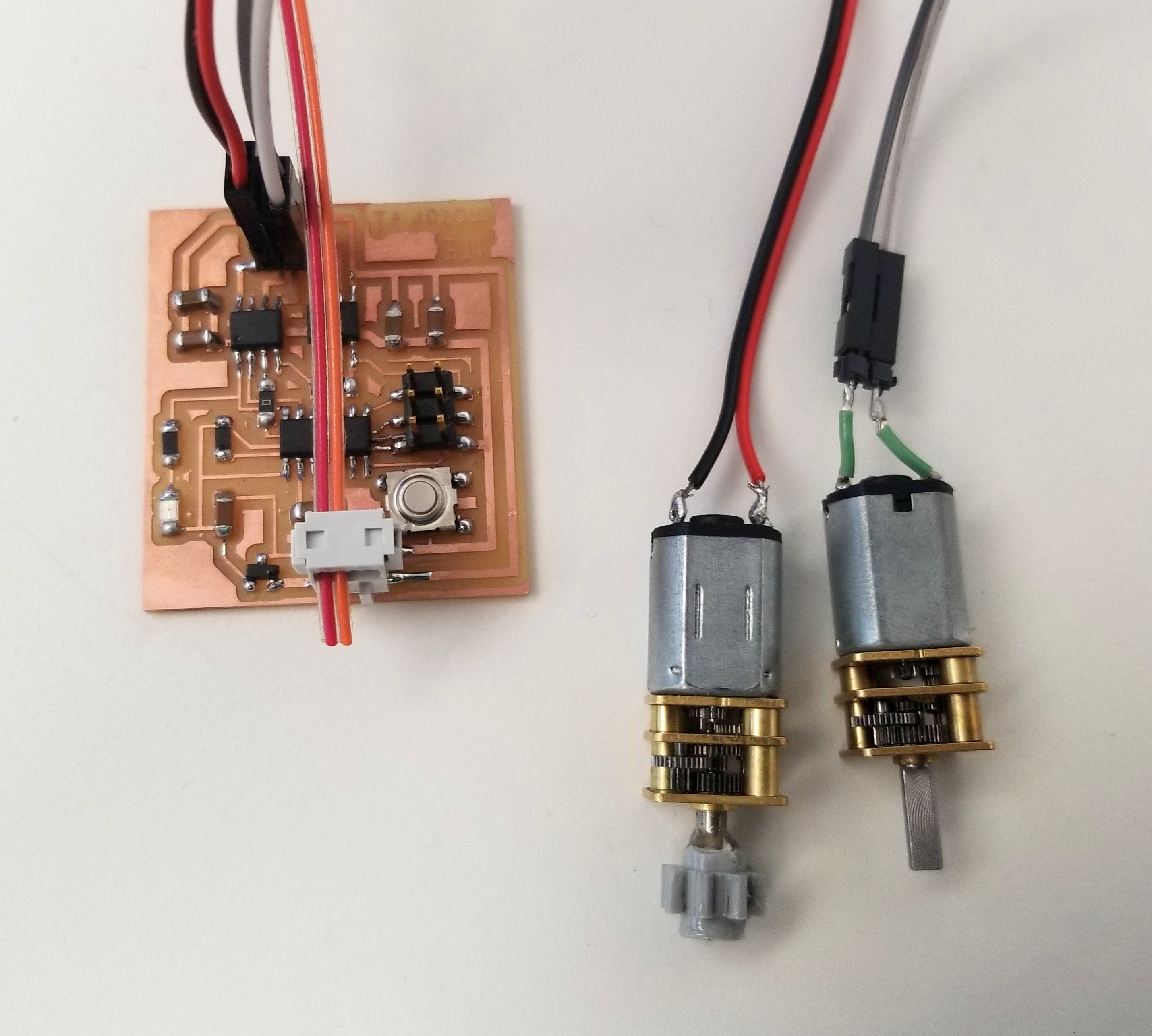
I found some spare Pololu motors in a drawer full of screws my lab, so I’m going to use those this week. I soldered on some wire and tested them both with a power supply . They are 6 V motors, and draw 60 or 100 mA. (They’re apparently slightly different motors.)
For programming, I started out with Neil’s hello world program for DC motors (C code, Makefile). Since I didn’t change the board much, all I had to do was double check that my output pins to the H-bridge were correct, then compile, and load. That all went flawlessly.
Then I actually connected the motor.
Nothing happened.
I rechecked my connections with a multimeter, and Rob helped me use the oscilloscope to check that the PWM signal from my board into the H-bridge was working as expected. But there was no power to my motor out of the H-bridge. I tried changing the program to use the pins for the other H-bridge. No dice.
Rob said that the H-bridges are sensitive, and I may have burnt mine out when I plugged in the power backwards. So I desoldered and replaced one of my H-bridges. Still no dice.
Then Rob realized the real problem: these H-bridges require the input voltage for the battery to be ~3 V higher than the reference voltage; both of mine were 5 V. So much for using my cool USB power cord, since USB supplies 5 V. I switched back to the power supply and was able to get the motors to run! I was a little worried about the motors, which seem to run at 6 V. (I tried turning up the voltage, but the motors got pretty hot, which seemed like a good sign that they are not intended to run at 12 V.) I was able to get it working once I got the input power up to ~7.4 V, but not much below that. For now, then, I’m chained to the power supply, but it does mean that I should be able to get this to run on a 7.4 V battery for my project.