Assignment: Design and build a wired and/or wireless network connecting at least two processors.
The final project deadline is coming up really fast, which means I want to aim this week’s assignment at helping my final project for time management. I’d really like to learn to use the NRF52 at some point, because the potential for low cost, real-time communication between devices (or in my case, robots) seems like it has some really cool potential. But since it appears to have something of a learning curve, is a completely different MCU than I’ve been using, and doesn’t have nice “Hello World” examples like the alternatives, I think I’ll leave that for the post-course future.
For project relevance this week, I’m planning to use optical communication, because that’s the only communication my project robots will have between each other. Specifically, they’ll use infrared light. The Kilobots also communicate using infrared bounced off of a surface, and they’re even programmed by infrared. So I’ve used optical communication before, but I have no idea what the robots are actually doing under the hood.
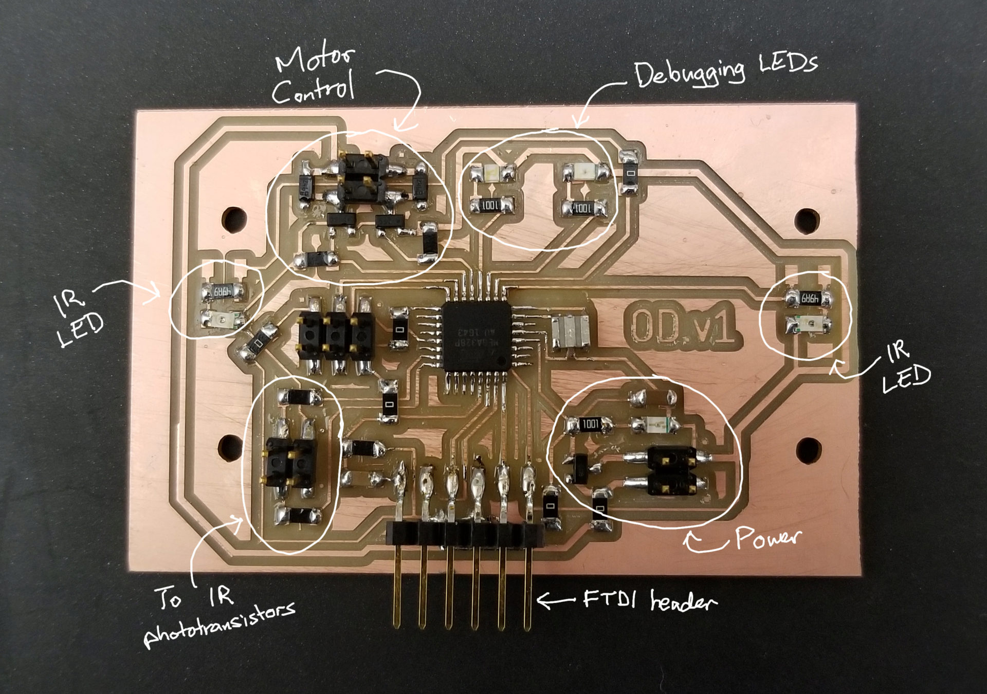
For board design, I’ll be using two separate boards this week. To send messages, I’ll use my input device board from two weeks ago (with an infrared LED and phototransistor). Messages will be received by the first version of my final project board. This board has two LEDs and 2 phototransistors, and is controlled by an ATMEGA328p (the first time I’m branching out from the ATTiny MCUs). It also has components for powering and controlling 2 motors (using MOSFETs) and 2 LEDs (green and blue) for debugging. My goal is to have the LEDs turned on and off by the messages from the other controller. (If I get the motor control up and running, I can also have the motors controlled by the incoming messages.)
For the communication design, I’m planning on using serial-type messages that will directly encode a few bytes of data in the light flashing, sent as fixed-sized “packets.” For now, I’m just having unidirectional communication between two boards, so I don’t need to worry about message conflicts. (Using more boards in the future, a CSMA/CD protocol could be used to avoid message conflicts.) It would also be good to have some sort of checksum byte for the receiver to verify the contents of the message. However, I’m not sure I’ll have time to get that working this week (with a different class having a looming project deadline next week).
Hardware
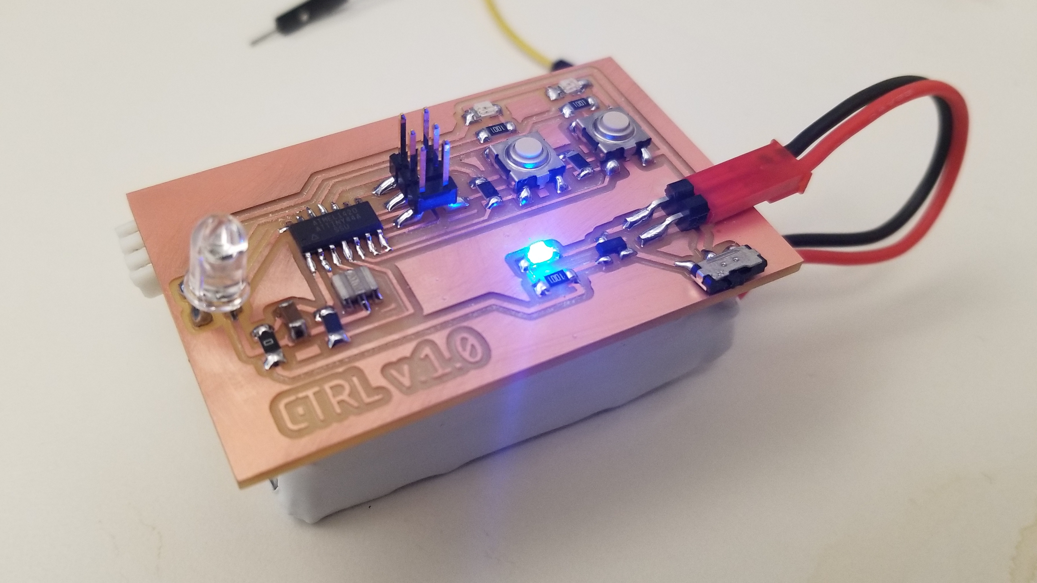
The new board I made for this week was aimed primarily at my final project, so I have information about its design on this week’s section of my project page. Here’s what the multi-functional board looked like after many failed attempts at soldering on those incredibly tiny pins on the ATmega328P:
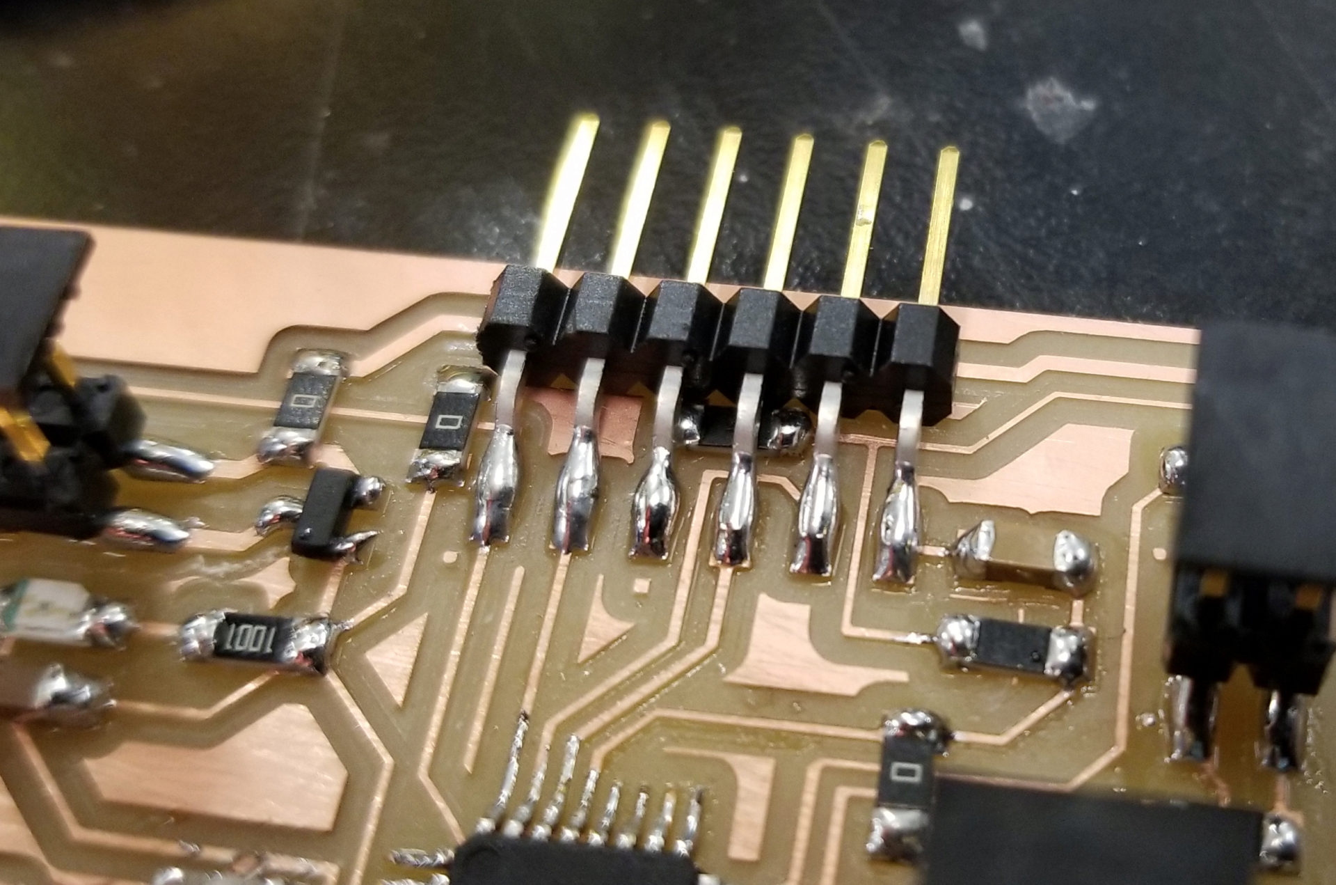
I also did a stupid thing with a resistor. After milling my board, I realized that I’d placed a resistor under the FTDI header. Luckily (since the PCB took 30 minutes to mill and I didn’t want to redo it), the resistor fit in the space between the pins and the plastic support, so I soldered it on and happily went about stuffing the rest of my board. And then I plugged in my board. That power LED looked way too dim. I went back to check my board design and realized my stupid mistake: I’d misread the the Hello World board design and put a 10k resistor in series with the VCC from the FTDI header. And it was the resistor located under the FTDI header. Crap. With solder wick, extra rosin, a solder vacuum, and a heat gun, I managed to angle the FTDI header pins up enough to desolder the resistor and solder in a tiny wire in its place. (I wasn’t in the Science Center at this point, otherwise a 0 Ohm resistor would have been a better choice.) I nearly pulled the traces off the board that connected the FTDI header, but luckily when I ran a beep test with the multi-meter after my “repair,” everything was still properly connected.
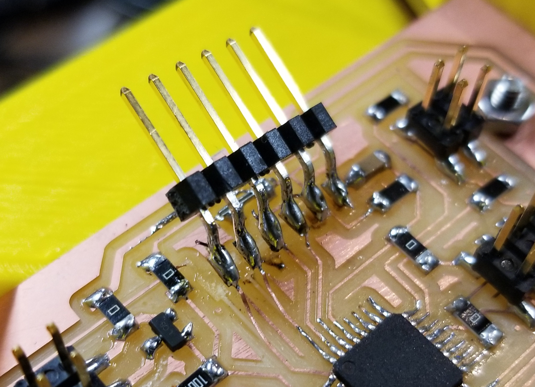
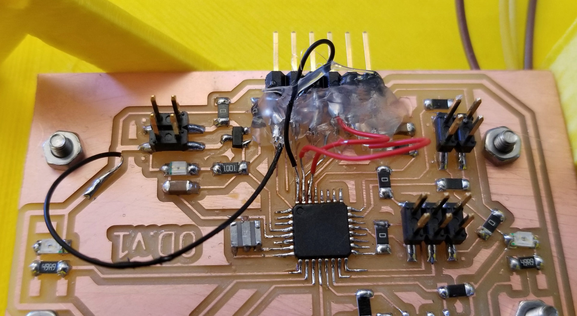
Then I did another stupid thing. While trying to multitask and program my board at a curling tournament, I accidentally yanked on the FTDI header and ripped it up. I tore up all but the far left (RTS) trace. Whoops. When I got back, this meant a lot of soldering tiny wires on to reconnect the components. I decided to leave the VCC header disconnected, since I’m not powering my board through FTDI. Unfortunately, I had traces to other things running through the FTDI header, so I did have to rewire the other things.
There were a few other issues with this board, but they didn’t affect this week’s stuff, so I’ll talk about that on my project page.
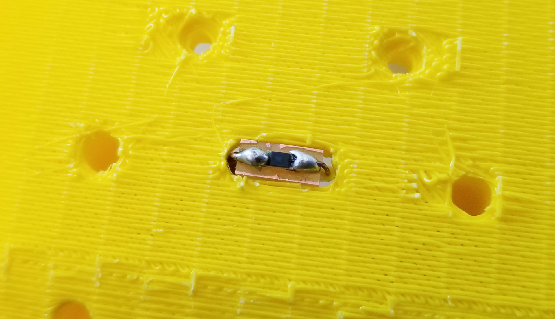
I also made a new version of my phototransistor board that is easier to fit and attach to my robot chassis.
Software
To make sure I could program the 328p board at all, I started by compiling and uploading the 328p blink code from the embedded programming week (C code, Makefile). I changed the LED pin to one of my debug LEDs, compiled, and programmed with my ISP header. It worked!
… with one issue. I tried to use program-usbtiny-fuses before programming and got this message:
avrdude: safemode: efuse changed! Was 7, and is now ff
Would you like this fuse to be changed back? [y/n]
If I say “no,” it fails. If I say “yes,” it hangs and does nothing. Google and the datasheet have failed me trying to figure out the problem here, but somehow the board still works. My guess is that this means it’s running on the internal clock instead of using the resonator. But I really don’t understand the fuses here.
I turned to the section issues on Gitlab and Richard Liu provided an alternative (and took the time to explain how he got it from Engbedded fuse calculator):
program-usbtiny-fuses: $(PROJECT).hex
    avrdude -p atmega328p -P usb -c usbtiny -U lfuse:w:0xd6:m
Next up, I have to figure out how to send messages with light. I’ll start with some combination of the code for sending serial messages over FTDI (to understanding encoding and decoding messages) and the synchronous light detection code (for turning the light on and off at the right rate, as well as detecting those on/off states). I’m essentially trying to do “serial over infrared,” which makes encoding and decoding messages straightforward.
I made some progress on the code for this before I was once again struck down by the chronic cough and mystery illness that’s been plaguing me all semester. Since this comes into play for my final project, I’ll get back to this over the next couple weeks.
Getting Back to This…
I went back and made some simple version of IR communication for the remote control in my project. Instead of repeating myself here, you can look at the Remote Control section of my project page
TL;DR: The remote control sends a single byte (plus start and stop bits) through its IR LED when you press the buttons. The robot receives these in its main loop. Using an interrupt at the same rate as the remote control, it checks for the values of the bits, but I didn’t figure out a good way to get the right framing for the bits to identify the correct byte value. So I’m controlling my robots with a binary thresholded IR signal.