week 11 (10/24 - 10/31): Machine Week
{bits & atoms by Open Assemblies}
Table of Contents:
* THINGS TO CONFIGURE IN FUSION BEFORE YOU START*
1. Introduction
This week's goal is to build a machine using Jake Read's open source parametric linear axes. The whole machine workflow is composed by: a) the Design workflow and b) the Machine workflow, whose steps are described in the following two sections, respectively.
* THINGS TO CONFIGURE IN FUSION BEFORE YOU START *
- Download and install the Dogbone addin for Fusion 360
- Download and install the Nester addin for Fusion 360. This will
allow you to lay down flat automatically all the machine parts so that you can arrange them in plane and check
if they fit in your predefined stock sheet dimensions. Here is also a video that shows how you
can do that manually.
2. Design Workflow
Software: Fusion 360 by Autodesk
General Design Workflow Steps:
1) Decide roughly about the machine's form factor and function.
2) Design one axis (very easy! thank you Jake!)
3) Make the Assembly.
4) Design machine chassis and other parts around the previous assembly.
5) Prepare CAM files
Specific Steps:
Step 1: Downloaded the RCT gantries Gitlab folder from here in a local directory of my computer.
Step 2: Opened Fusion and made the Data Panel on the left visible.
Step 3: Created a New Folder and named it as "*RCT GANTRIES*".
Step 4: Using the Upload button tab I uploaded all the files contained within the sub-folder of the RCT gantries Gitlab folder with the name CAD.
Step 5: Create a New Design by pressing the File tab button.
Step 6: Saved the design with the name "machine-1".
------------------
Aside: {Probably my final machine will have axes of different form factors (travel lengths, rail dimensions etc.) or maybe all
my axes will have the same form factor. In both cases, I need to decide if your machine assembly will be fully parametric
(axes plus chassis and other parts) or no (everything else except the axes).
In the 1st case (fully parametric), I will start by modifying a single axis, configure its dimensions, save it and then import it
inside the machine design tightly linked to the Fusion model so that everytime I update the Fusion model of the axis design, the Fusion
assembly will be updated.
In the 2nd case (not fully parametric), I will again start by modifying a single axis, configure its dimensions, save it
export it as a STEP model and then import it inside the machine design. In that case, the single axis Fusion model
won't be tightly linked to Fusion machine assembly and I won't be able to update the assembly design by changing the Fusion single axis model.}
-------------------
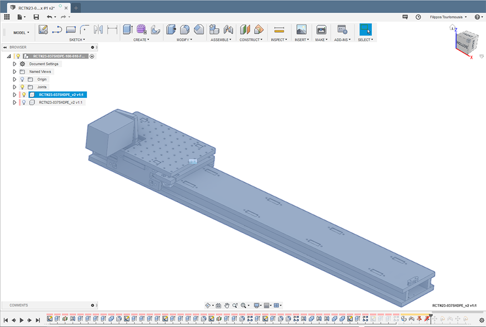
Step 7: Opened the Fusion model named as RCTN23-0375HDPE-100-610 by right-click and Open.
Step 8: Activated the Root Node on the tree model by right-click and Activate.
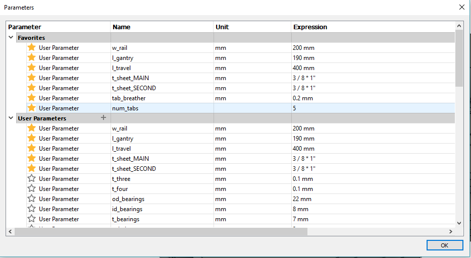
Step 9: Modified the imported axis form factor by using the Change Parameters under the CREATE tab.
I modified the length of the gantry (l_gantry). All dependent geometric parameters are updated accordingly
and after some computing time the CAD model is updated:
The final parameter values I chose are shown below:
------------------
Aside: {Now I have 1 single axis geometrically configured. I need to ask myself and check my hand drawings if all the machine axes will have the same form factor. Lets say all axes will have the same form factor. This will make my life easier as soon as I start making the assembly. The next thing I need to ask myself is if I want my machine assembly to be fully parametric. I VOTE FOR THAT. So, before moving to the following steps I made 2 decisions:
- all axes same form factor
- fully parametric machine assembly} -------------------
Step 10: Opened the Fusion file that I previously created for the machine assembly and named it "machine-1".
Step 11: Imported the single axis Fusion model by Right Click ==> Import. The whole axis (Bodies & Sketches) is imported as a New Component.
Step 12: Activated the axis component and break the link from the original by Right click ==> break Link. Since all my axes have the same form factor, I can update the axes dimensions locally using the Change/Modify Parameters
Step 13: Grounded the axis by clicking on the tree model, right-click and Ground. Now, I'm ready to start performing assembly modeling using a bottom-up approach starting from the x-y gantry, where the printbed will be mounted.
Step 14:Copied (right click ==> Copy) and pasted (right click ==> Paste or Paste New). I used Paste because when I update the position of certain blocks in the x-axis, the exact same blocks will be automatically updated in the y-axis. After the part is pasted, I rotated it at 90 deg and moved it roughly above the x-axis and then I brought the gantry and the surrounding attached bodies to the middle of the axis length:
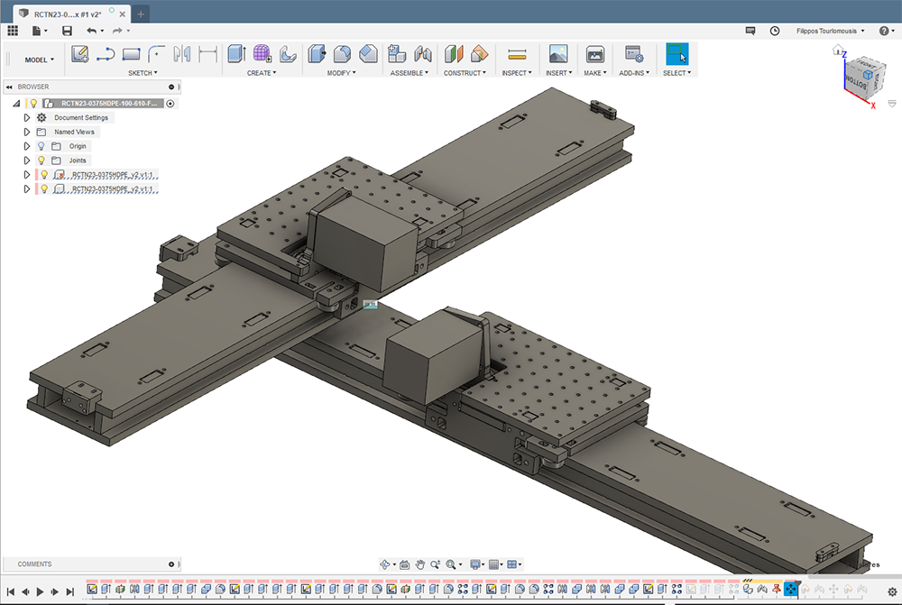
Step 15:Then, I joined the middle point of the rail's length side to the middle point of the gantry's width u sing the rigid joint option under Assemble ==> Joint :
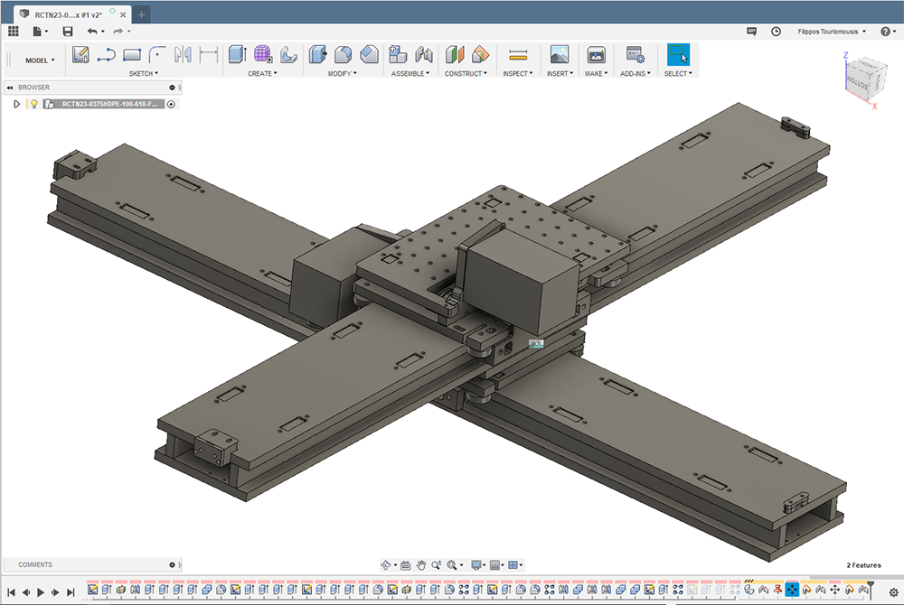
Now, I have an XY-stage and I can start designing my machine by importing or making new components around this stage.
Before moving on to to finish my machine assembly, I to do a single axis milling trial run. There is one last step before that
: prepare CAM files.
Step 16: I created a new component and named it: "CAM layout".
Step 17: Copy and Pasted all components under the "CAM layout" component.
Step 18: Created a new component and named it as "HDPE-stock". Sketched and extruded under this component
a part with the same length, width and thickness of my stock sheet.
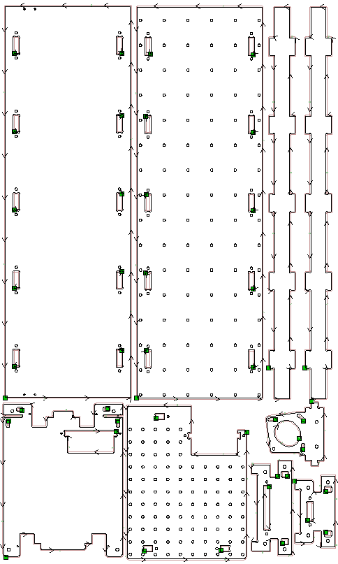
Step 19: Laid everything flat using the Nester plugin or the manual approach I previously linked.
Step 20: Arranged all the components so that they can all fit within the available stock area without wasting a lot of stock material.
Step 21: Projected sketches and exported each one as dxf. These are the files that I used to generate the
CAM operations for Shopbot after importing them VCarve Pro.
I really like this approach. Now, whenever I update my model, the projected sketches are automatically updated:
3. Rapid Prototyping Workflow
A) Setup all CAM operations
Step 1: I opened VCarve Pro and set up the stock area dimensions. Measured length and width of your available
HDPE sheet and import the dimensions in mm.
Step 2: Imported the exported dxf files by: Files ==> Import Vector and check their relative scaling with
the stock sheet.
Step 3: Made sure that all parts are continuous polyline by selecting each one of them and:
Highlight ==> Join open vectors
Step 4: Arranged all parts so that I don't waste material but also leave some space (~1 in) between them.
Step 5: Selected all holes.
Step 5: Setup a drilling toolpath with the following settings:
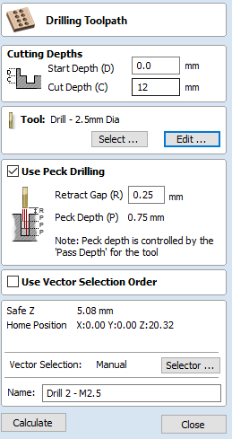
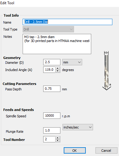
Chose the tool with the following name:
Step 6: Selected all pockets.
Step 7: I setup a 2D Profile Toolpath for cutting them out by:
Chose the same tool as before tool and the settings are:
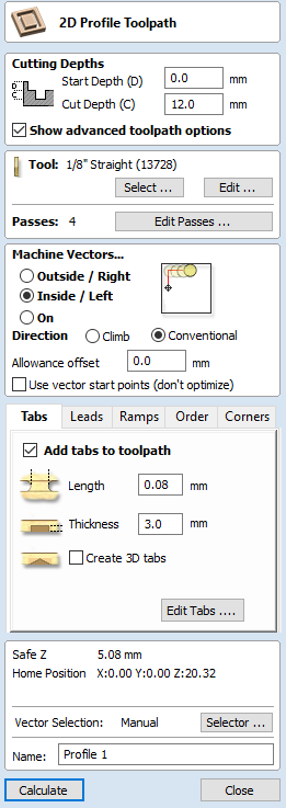
SOS make sure to choose the Inside/Left option. These are inside cuts:
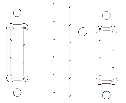
Step 8: Selected the outlines of all parts.
Step 9: Setup a 2D Profile Toolpath for cutting them out by:
Chose the same tool as before tool and the settings were:
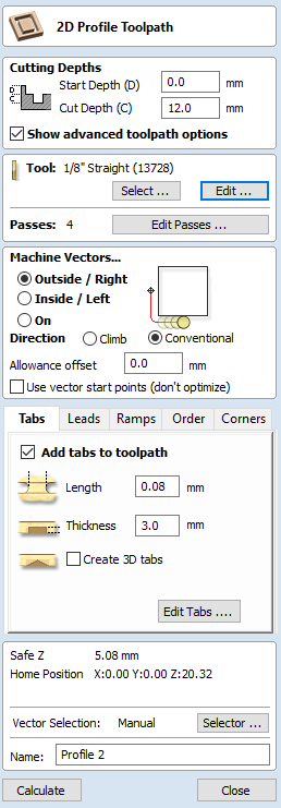
SOS made sure to choose the Outside/Right option. These are outside cuts:
Step 10: Saved each toolpath.
B) Setup the machine (Shopbot) and mill the parts with SARA FALCONE
We already know how to setup the machine and cut everything out.
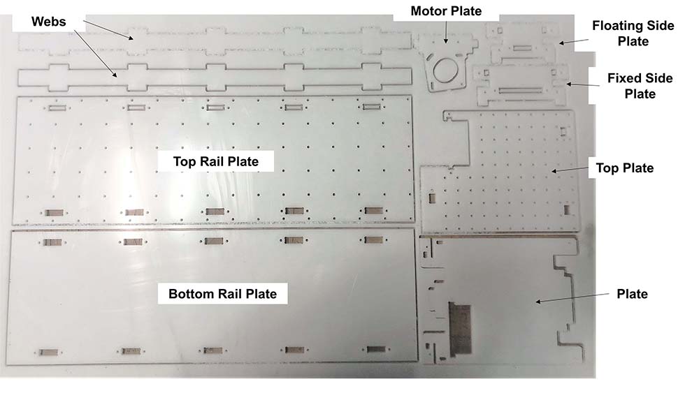
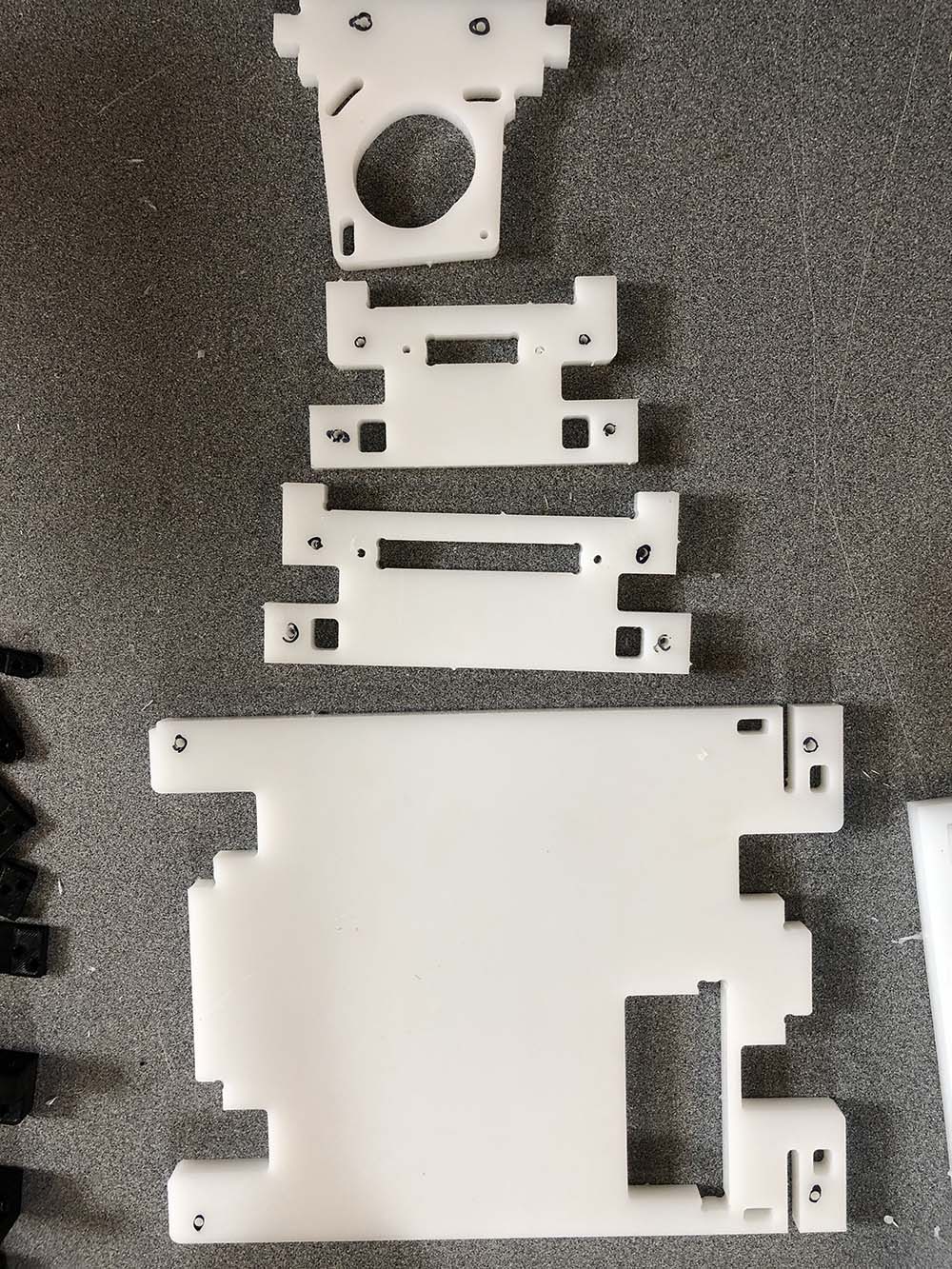
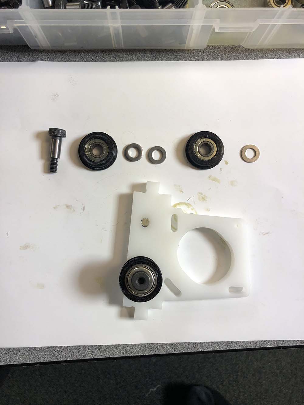
Here are all parts for assembling a single ais annotated using the same naming convention as the single axis Fusion design file:
C) Assembled the axis with SARA FALCONE
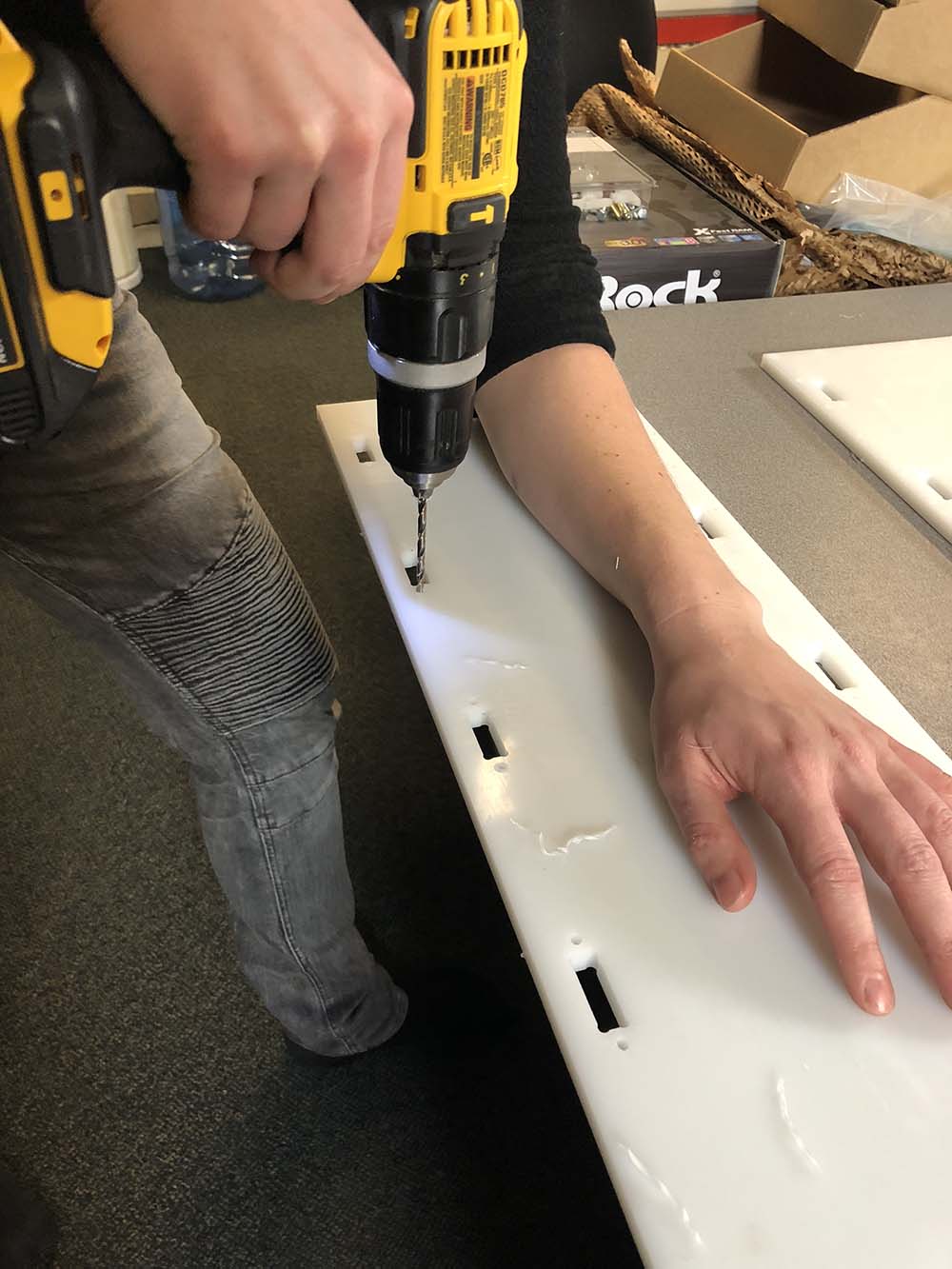
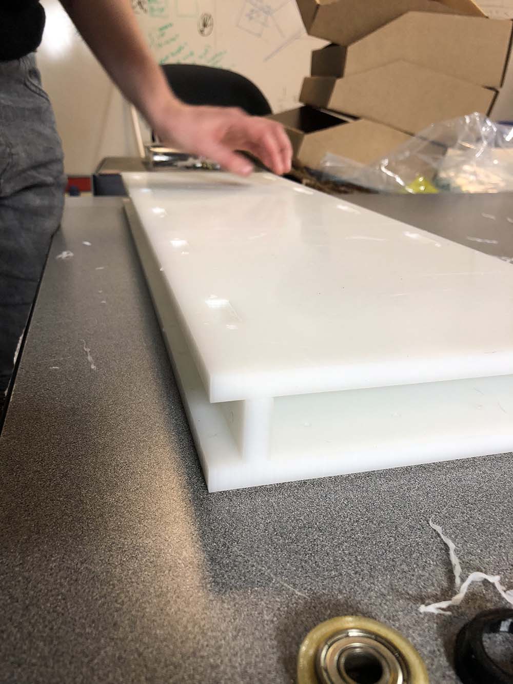
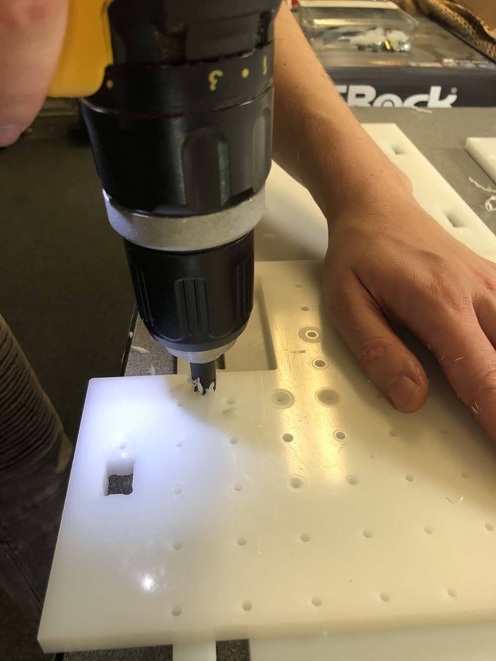
Step 1: Started with the top and bottom rail plates by opening up the holes around the pockets using the drill
and a drill bit with a diameter slightly larger than the diameter of the Button Head Thread-Forming screws (No. 6, 3/4").
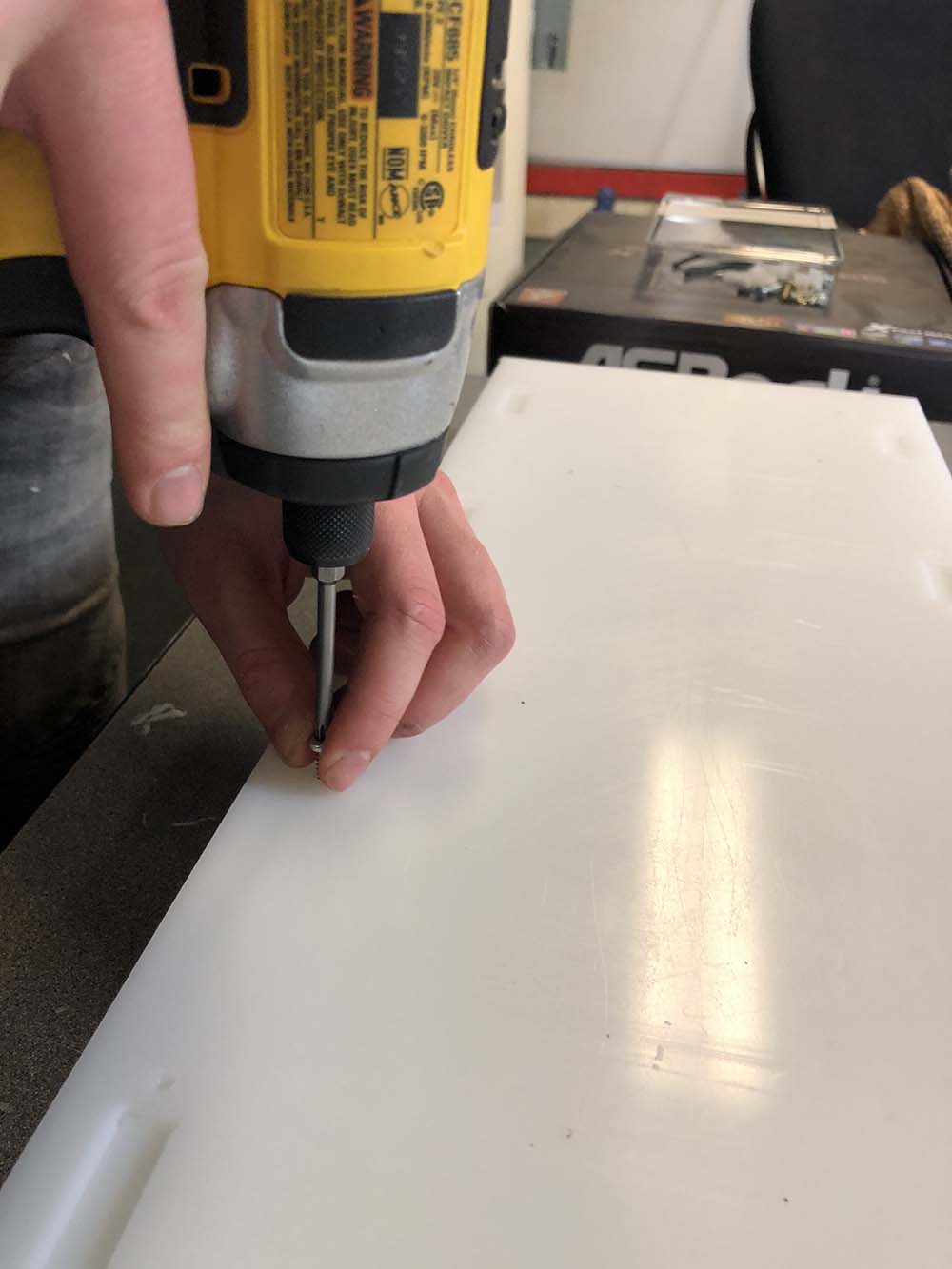
Step 2: Assembled the webs and the rail plates together and then predrilled holes on the webs by passing a drill
bit with a diameter slightly smaller than the diameter of the Button Head Thread-Forming screws (No. 6, 3/4").
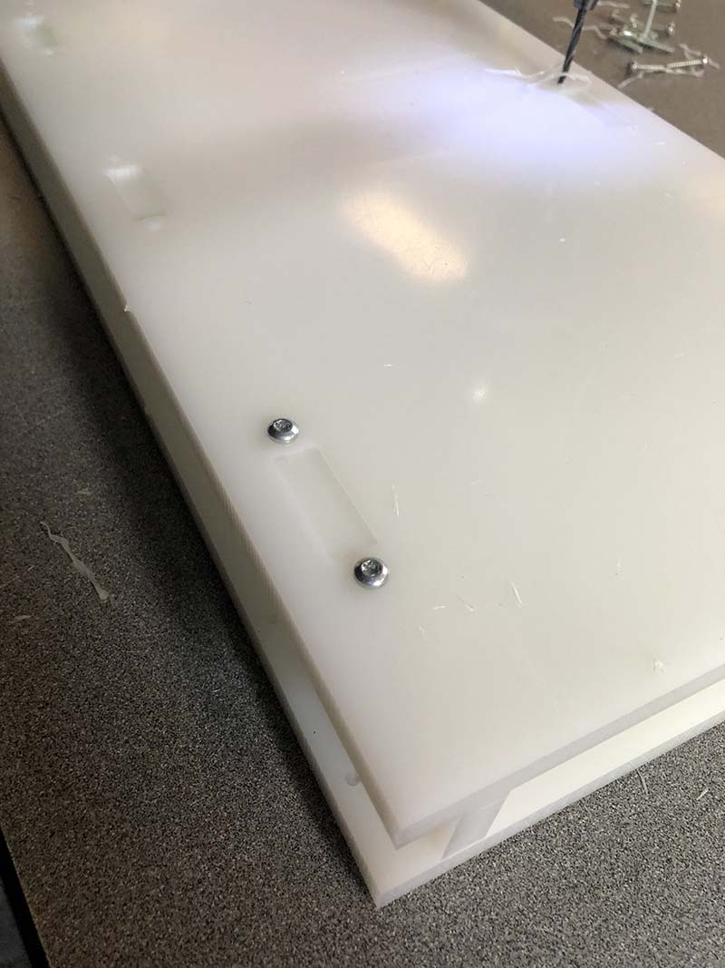
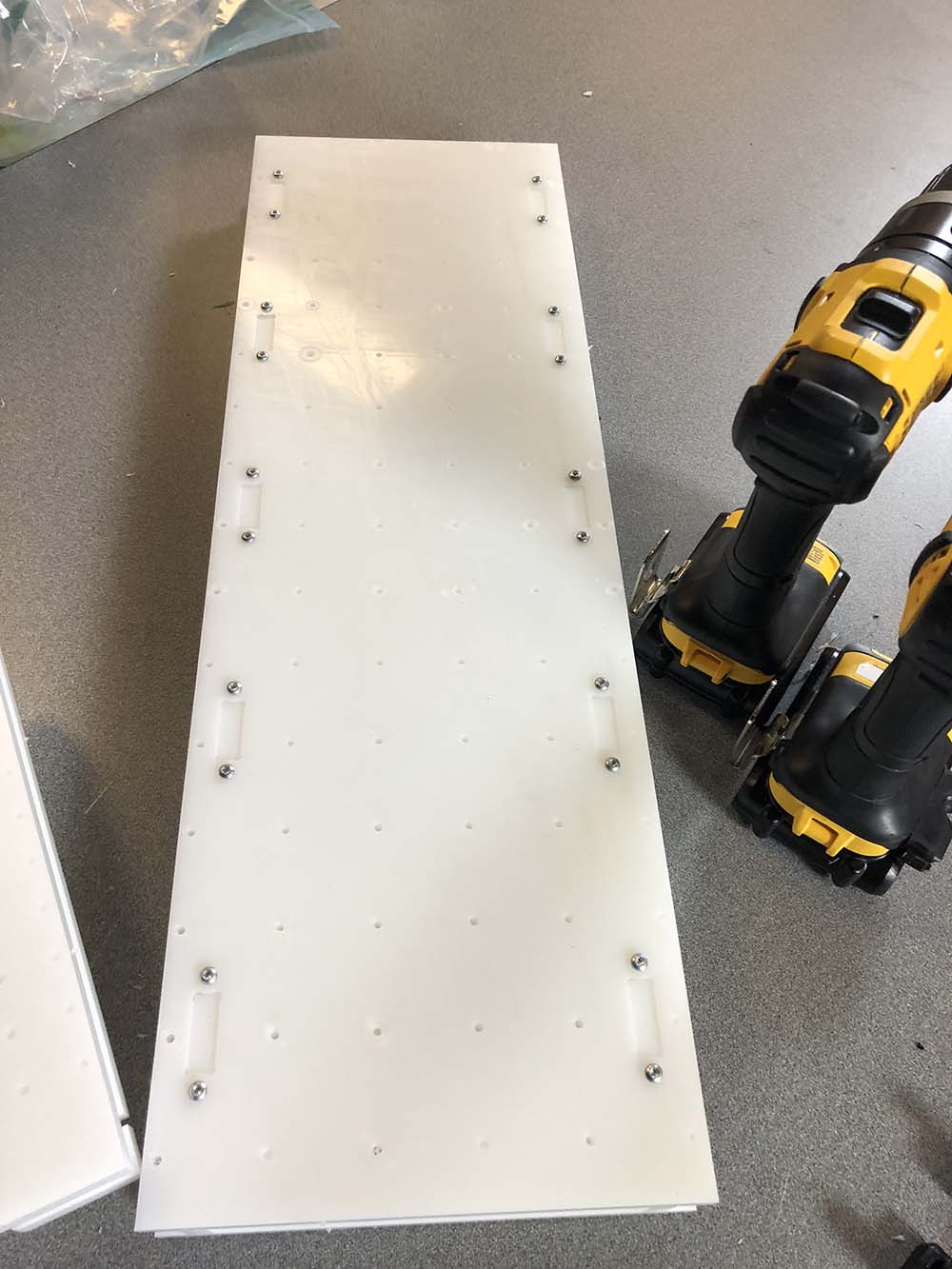
Step 3: Screwed down the Button Head Thread-Forming screws (No. 6, 3/4") around every rail pocket on both rail plates
and my axis chassis is ready.
Step 4: Took the top plate and opened up the holes around the pockets the same way. Then, countersinked the
opened holes:
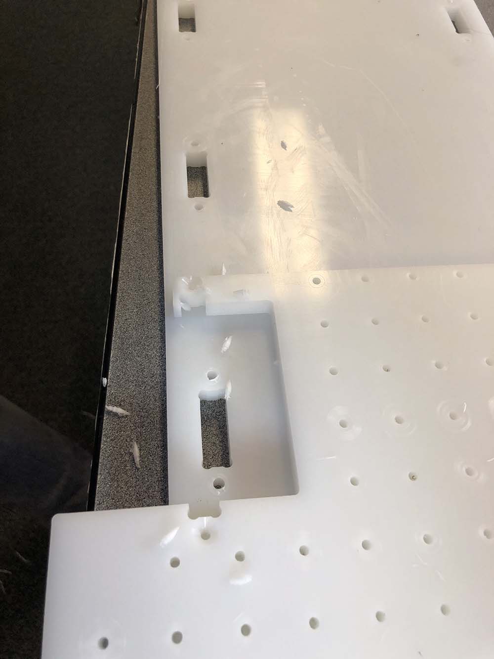
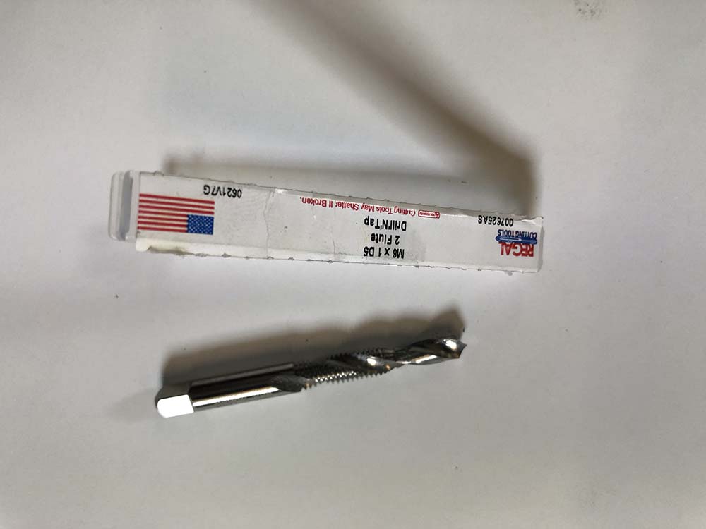
Step 5: Took the top plate, the motor plate, the floating and the fixed side plate and mark down the outline
of M6 holes with a sharpie. Then, using the appropriate bit that is both a tap and a drill, taped and drilled the marked holes.
Step 6: Took the motor plate and using the assembly schematic provided by Jake mount the
roller bearing and the shoulder screws. Be careful to use the correct shoulder length. Double-check with the caliper.
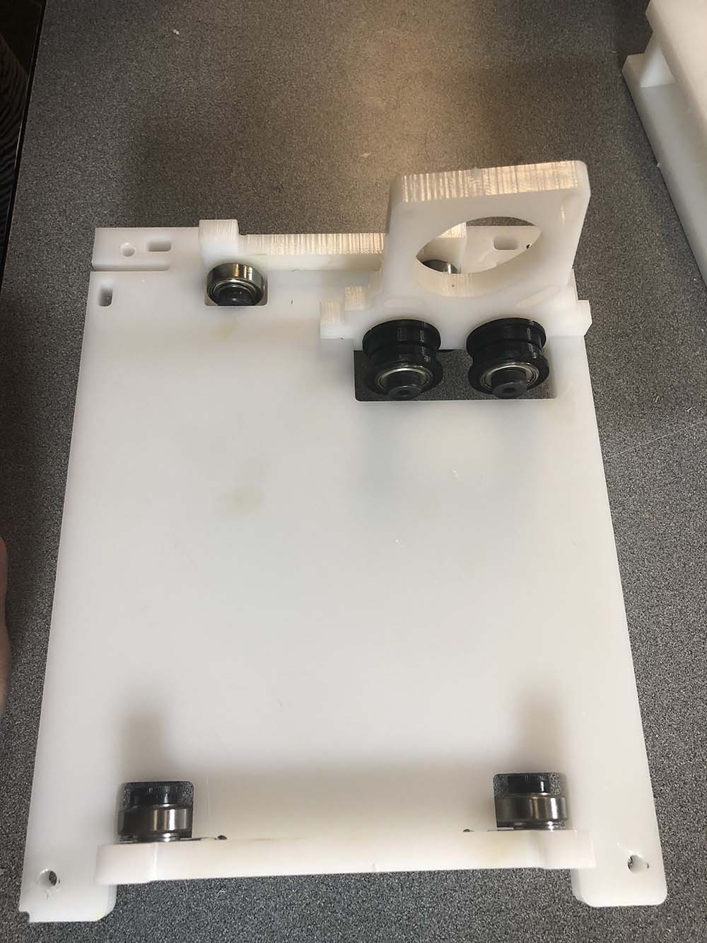
Step 7: Did the same using the the floating and the fixed side plate and put roughly everything together to check
how they are going to fit before you screw everything down.
Step 8: Screwed everything down using the Button Head Thread-Forming screws (No. 6, 3/4"). Made sure to open up
and predrill holes in the appropriate locations like we did before (Steps 1-2).
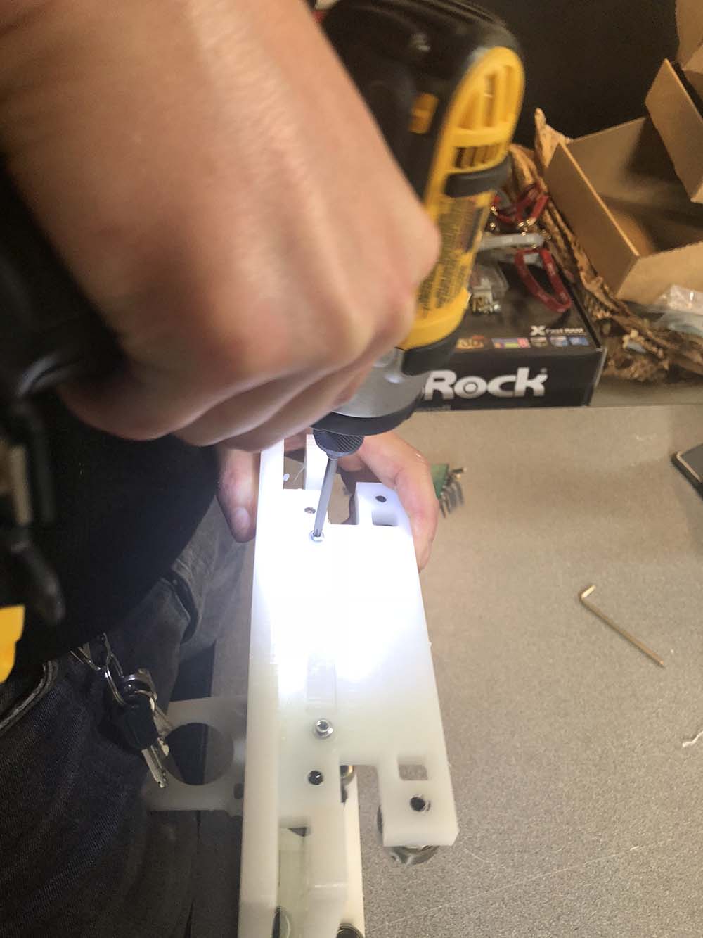
Step 9: Mounted the top plate to the previously assembled part. Made sure that the appropriate holes are opened
and counter sinked. As previously described, pre-drilled holes on the side plates by passing the drill bit through the opened holes.
Step 10: Screwed the top plate down using the Flat Head Thread-Forming screws.
Step 11: Mounted the motor on the motor plate using M5 screws and nuts, as the
assembly schematic provided by Jake shows.
Step 12: Checked how the motor-plate assembly rolls through the rails and then remove it.
Step 13: Cut the belts in an appropriate length.
Step 14: Using the 3D printed parts for belt tension and checking again the
assembly schematic provided by Jake mount the belt on
one end of the top rail plate.
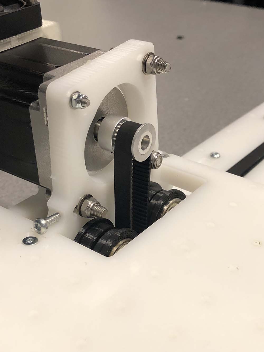
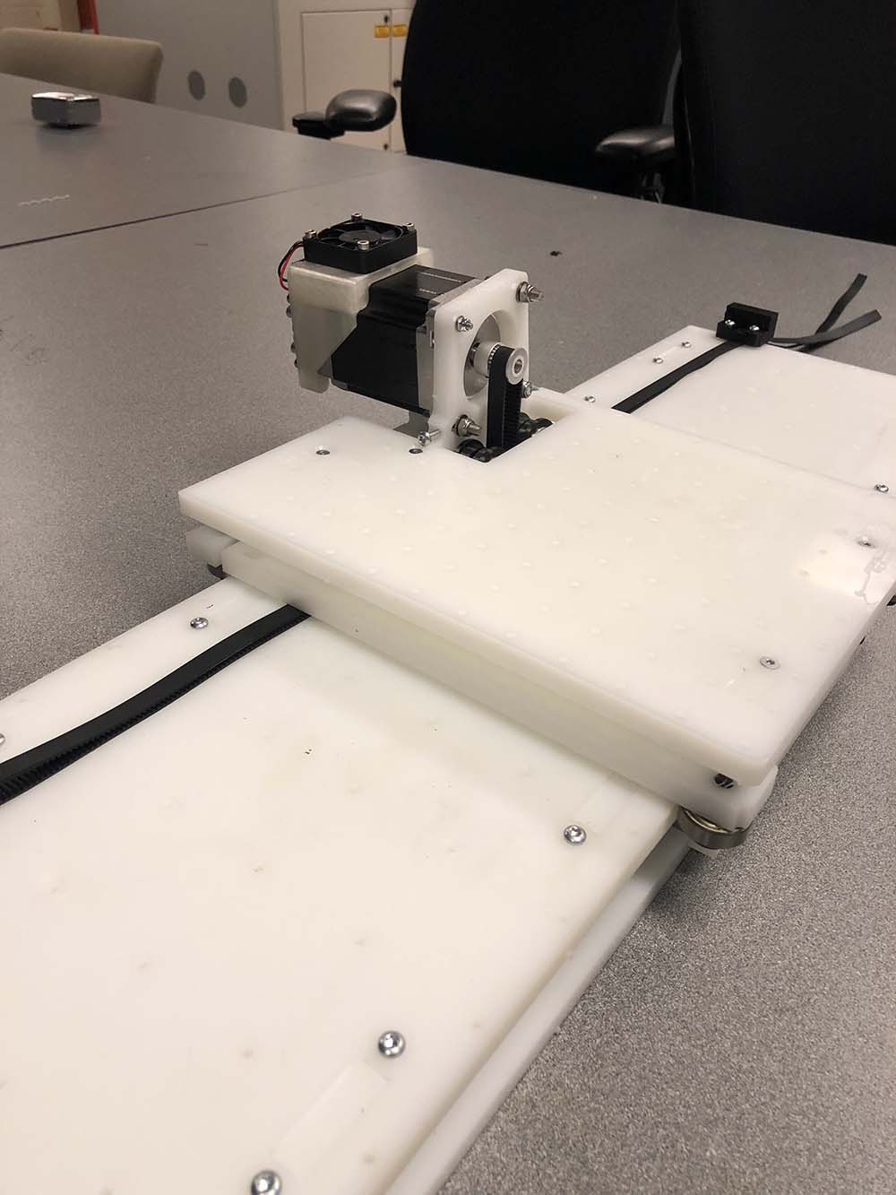 Step 15: Passed the motor-plate assembly through the rails and mount the 3D printed parts for belt tension
on the other end of the top rail plate. Made sure to pull the belt so that it is tightly tensioned at the
GT2 Pulley mounted on the motor shaft.
Step 15: Passed the motor-plate assembly through the rails and mount the 3D printed parts for belt tension
on the other end of the top rail plate. Made sure to pull the belt so that it is tightly tensioned at the
GT2 Pulley mounted on the motor shaft.
I am ready to mount electronics and test motion! Back to Jake's
link for the rest.