Electronics
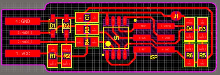
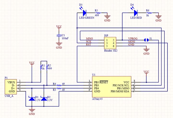
This week was a relatively straight-forwardly technical, with less emphasis on design. The aim was to make a FabISP programmer from scratch: milling the PCB, soldering the components and programming the programmer (so that it can programme more programmers). This week's assignment was pretty much technical and focused on the development of basic skills regarding electronics production. The aim was to construct a version of an ISP programmer/board that could be made using a milled PCB and electronic components, that should be soldered to the board.
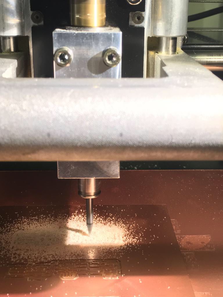
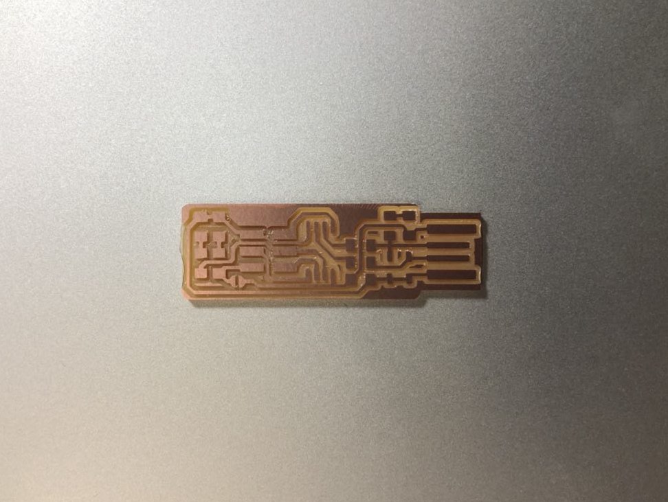
Milling the PCB
Milling the PCB was a bit challenging at the beginning. The first cut of the traces were not deep enough, and while trying to restart the machine I had problems getting it back to the origin point. However, after having support from TAs, the program got back to its usual operation and the cutting process went well.
Here are some guidelines for the whole process:
1) using a double-sided tape, stick the cupper bords, both sacrificial and the fr1 board onto the machine bed, watching out the line of reference in the front
2) change the endmill > 1/64: trace | 1/32: outline - this process has to be done carefully for it not to fall and break the tip or the board. Press down to mechanically lower the endmill while securing the endmill with your fingertips. Once the endmill tip is flushed with the board, screw in the top of the endmill, securing it in place.
3) in the computer start at mods.cba.mit.edu > click with the right bottom > programs > open server program > roland; mill; mdx-20; PCB
4) load the png drawing > choose between mill traces (interior) or mill outline (exterior) > set up offset number (the higher the number the finner it will be) > press calculate > move to origin (setting up the right origin point desired)
Soldering
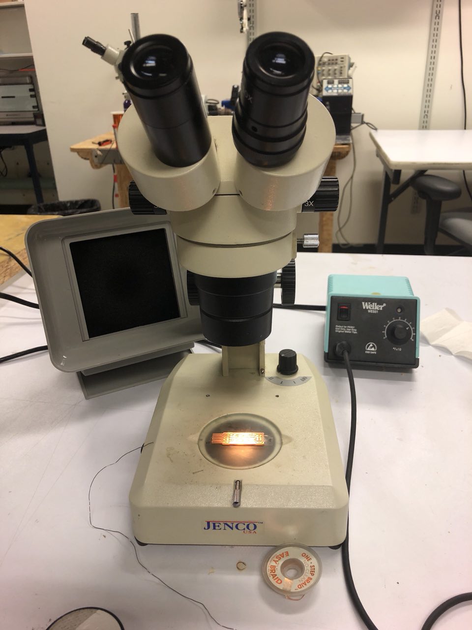
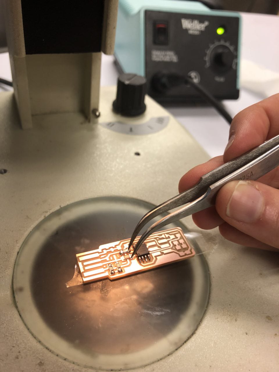
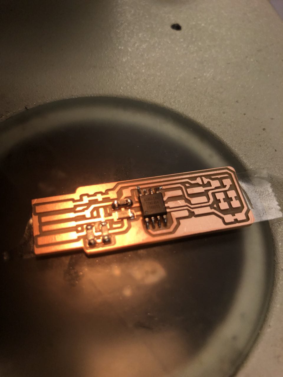
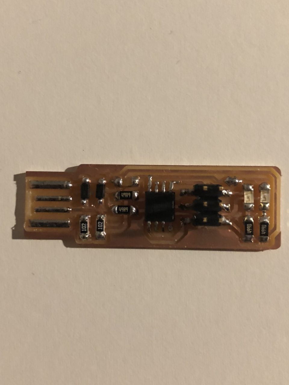
The next step was to solder the quite small components onto the PCB. After having organized all the tiny componets needed and having acknowledged their right position on the board, I nailed the PCB with double-sided tape under the microscope to have it more stable. The fist two couple of soldered pieces were a true nightmare, I did not think I would have the entire board done, but progressively it became very intutitive and fun.
After soldering I went through some tutorials for BASH programming, but since it was the first time doing it, it seemed quite hard to move further. I have also had some difficulties to commit the changes I have done this week at my website, since it was the first time doing it locally (the week before I was still using the web interface). With a great guidance from Sam, I managed to get it done and wrote a little instruction set for myself and others that might be interested. The biggest difficulty was to have the files I had moved in my local folders and subfolders recognized by git. In order to do this, I had to replace the files to their original folder location and redo the move step to subfolders through git itself. To do this, Sam showed me the command "git mv", which is illustrated by the folliwing images:
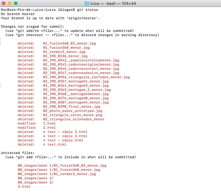
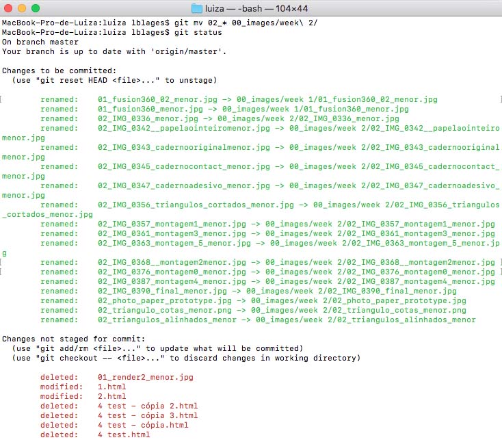
Here it is seen many files that git could not recognize anymore because I had just moved them locally and not through git. The following image shows the usage of the "git mv" command:
1) check the changes that you have made by typing "git status"
2) identify the files you have moved but which are still not recognized by git. In my case, they were shown as deleted
3) type "git mv", than the name of the file (since I wanted to move many files to the same folder at once, and they all have their names starting with number 02, I have just typed 02 and then pressed tab twice to have git showing me all the files named with 02). Git than showed me all the files named as 02 and I checked to confirm that all those files were the files I inteded to move. After this checking I typed "*" to select all the files showed. Following the "*" type the location you want to move your files to, and voilá, that is it!
This week was a relatively straight-forwardly technical, with less emphasis on design. The aim was to make a FabISP programmer from scratch: milling the PCB, soldering the components and programming the programmer (so that it can programme more programmers). This week's assignment was pretty much technical and focused on the development of basic skills regarding electronics production. The aim was to construct a version of an ISP programmer/board that could be made using a milled PCB and electronic components, that should be soldered to the board.
Milling the PCB
Milling the PCB was a bit challenging at the beginning. The first cut of the traces were not deep enough, and while trying to restart the machine I had problems getting it back to the origin point. However, after having support from TAs, the program got back to its usual operation and the cutting process went well.
Here are some guidelines for the whole process:
1) using a double-sided tape, stick the cupper bords, both sacrificial and the fr1 board onto the machine bed, watching out the line of reference in the front
2) change the endmill > 1/64: trace | 1/32: outline - this process has to be done carefully for it not to fall and break the tip or the board. Press down to mechanically lower the endmill while securing the endmill with your fingertips. Once the endmill tip is flushed with the board, screw in the top of the endmill, securing it in place.
3) in the computer start at mods.cba.mit.edu > click with the right bottom > programs > open server program > roland; mill; mdx-20; PCB
4) load the png drawing > choose between mill traces (interior) or mill outline (exterior) > set up offset number (the higher the number the finner it will be) > press calculate > move to origin (setting up the right origin point desired)
Soldering
The next step was to solder the quite small components onto the PCB. After having organized all the tiny componets needed and having acknowledged their right position on the board, I nailed the PCB with double-sided tape under the microscope to have it more stable. The fist two couple of soldered pieces were a true nightmare, I did not think I would have the entire board done, but progressively it became very intutitive and fun.
After soldering I went through some tutorials for BASH programming, but since it was the first time doing it, it seemed quite hard to move further. I have also had some difficulties to commit the changes I have done this week at my website, since it was the first time doing it locally (the week before I was still using the web interface). With a great guidance from Sam, I managed to get it done and wrote a little instruction set for myself and others that might be interested. The biggest difficulty was to have the files I had moved in my local folders and subfolders recognized by git. In order to do this, I had to replace the files to their original folder location and redo the move step to subfolders through git itself. To do this, Sam showed me the command "git mv", which is illustrated by the folliwing images:
Here it is seen many files that git could not recognize anymore because I had just moved them locally and not through git. The following image shows the usage of the "git mv" command:
1) check the changes that you have made by typing "git status"
2) identify the files you have moved but which are still not recognized by git. In my case, they were shown as deleted
3) type "git mv", than the name of the file (since I wanted to move many files to the same folder at once, and they all have their names starting with number 02, I have just typed 02 and then pressed tab twice to have git showing me all the files named with 02). Git than showed me all the files named as 02 and I checked to confirm that all those files were the files I inteded to move. After this checking I typed "*" to select all the files showed. Following the "*" type the location you want to move your files to, and voilá, that is it!