Lamp
For my final project, I decided to make a lamp that I could turn on and off remotely.
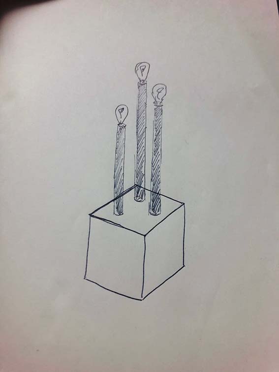
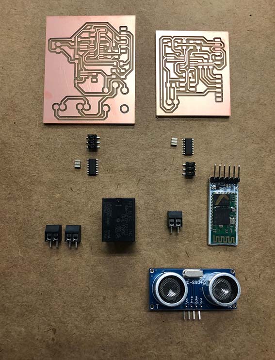
My idea was to conceptualize the project from devices we have learned in class. Therefore, I decided to use an Ultrasonic Sensor as the trigger for turning the light on and off, and a Bluetooth module HC - 05 to transmit the signal from the sensor and allow the procedure to operate remotely.
As a starting point, I have visited some tutorials as well as other projects that have used Bluetooth sensor to remotely activate different mechanisms, like the following:
http://fab.cba.mit.edu/classes/863.17/CBA/people/oscarrosello/index.html#portfolioModal11
https://www.filipeflop.com/blog/controle-modulo-rele-arduino/
https://portal.vidadesilicio.com.br/hc-sr04-sensor-ultrassonico/
https://www.arduinoecia.com.br/2016/11/digispark-attiny85-ide-arduino.html
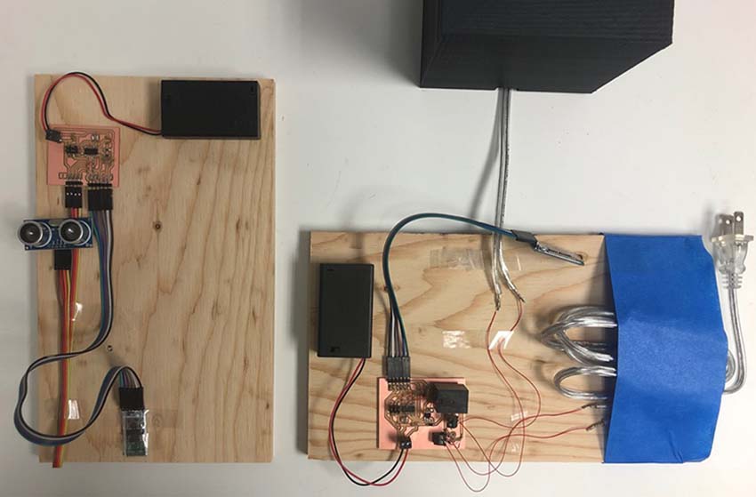
I haven't found a reference using exactly the same devices I choose to work with, however, these tutorials were good starting points to know to start thinking about the project and to understand deeper the functionality of each of its parts separately. To start thinking about the project, I knew I would need 2 different boards, both with separate energy supply, one connected to the lamp and the other independent and transportable, to be used remotely.
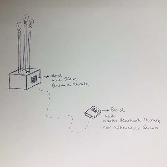
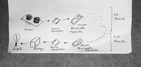
The basic operation for this system would be:
Ultrassonic sensor captures change of distance of objects in front of it, for example, a hand moving closer to the sensor. This movement- change of distance- is captured by the sensor, which will send a signal to the microcontroller of the correspondent board, which by its turn communicates with the master bluetooth module, which will send a signal to the slave bluetooth module, which is connected to the second board, directly attached to the lamp.
Knowing the most basic procedure and components I would have to have to make the board work, I started to research deeper how I would connect them in a board and which other complementary basic components I would need.
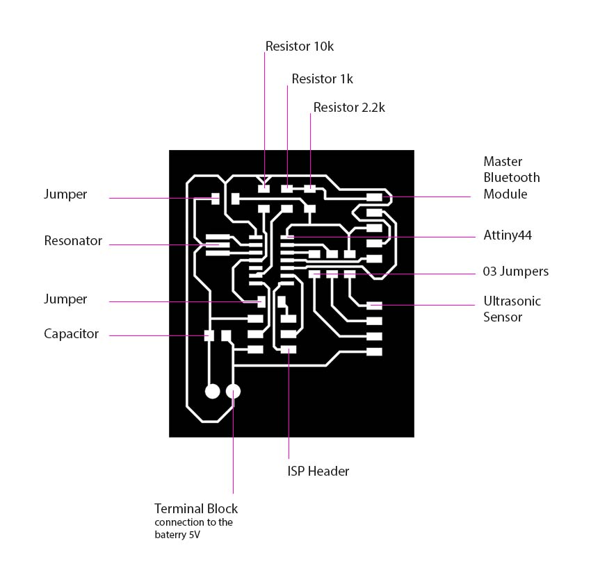
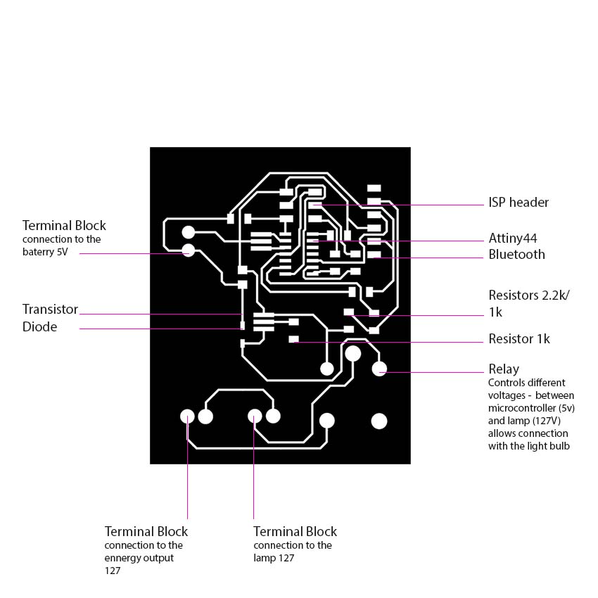
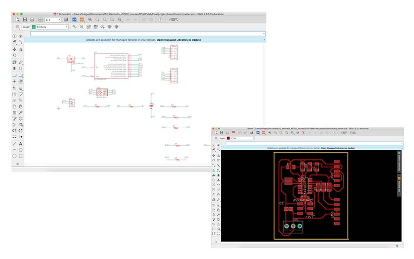
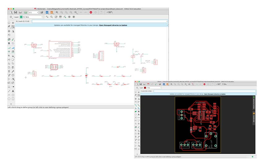
With the help from Natan Monticeli, a guru in electronics, I could trouble shoot the board design and the connection between the components to have the board working. I have then done the design in eagle for each of the boards, master and slave.
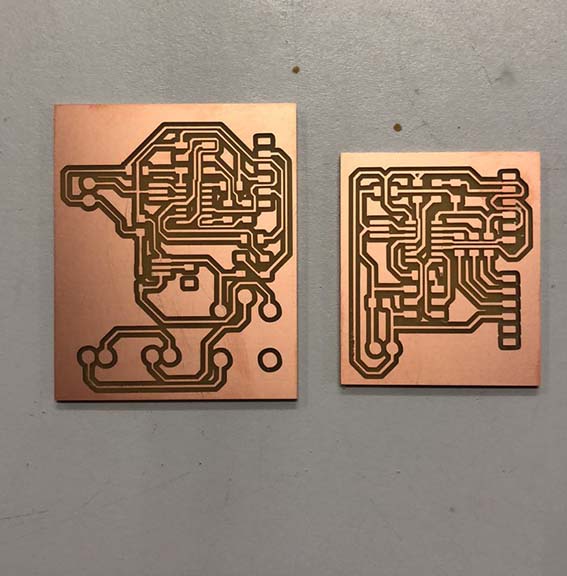
Since I have done a just one-sided board (with all the components soldered at the same side), it was pretty hard to draw all the traces without jumpers, so I ended up having many (!!!) of them. After milling and soldering the slave board, I have realized that I somehow forgot to draw one trace connecting one of the resistors to the microcontroller, and I ended up doing a big jumper to connect them (what was certainly not ideal, but solved the problem)
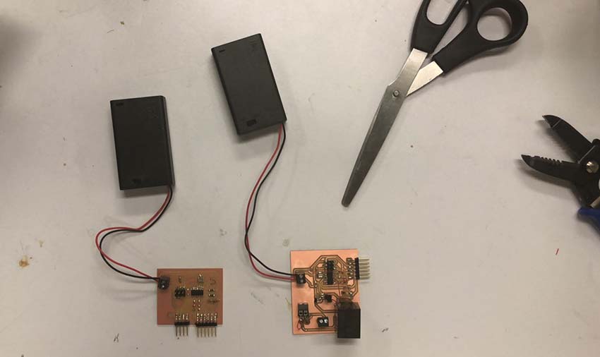
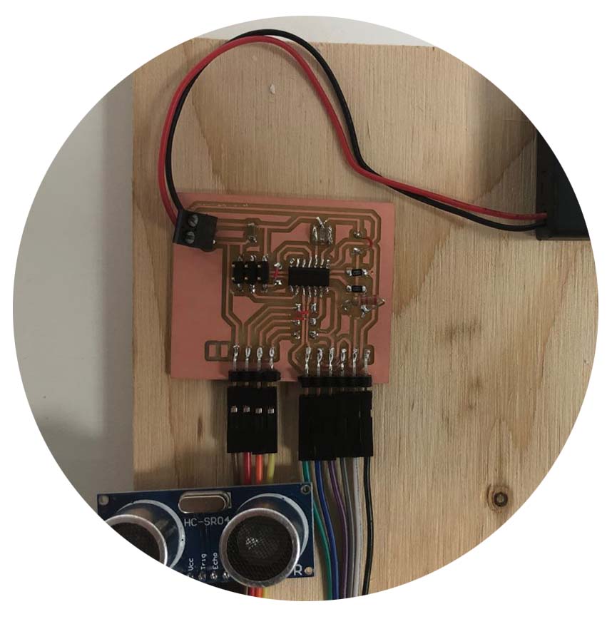
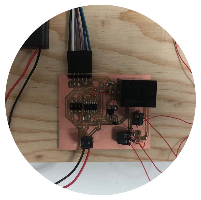
Both boards worked when I connected them to my USBtiny programmer, both Bluetooth devices lighted up. I had both boards connected to the external battery, both with 3,5V (ideally they would be connected to 5V - but I used rechargeable batteries with 1,5V each).
With the boards done I have started the programming part. I used a basic programming code as a reference, and with the help of a programming, guru changed it to correspond to the needs of the project.
The basic programming concept was to programme the Bluetooth module form the master board as the signal 'sender' and the Bluetooth module from the slave board as the 'receiver'.
For that, two separate programming steps should be done in the master module. The first step was to "lock" the key pin of the Bluetooth module, transforming it into only a signal emitter. The second step is to programme it to actually send the signal and to connect to the second Bluetooth module. This code will teach the module how it should convey a message to the other Bluetooth module. This step happens through a 'library' called software serial. This library will enable communication. Beyond the libraries, the code also establishes variables for the ultrasonic sensor, which will establish through a predefined distance, if the lamp should turn on or off. If the sensor detects movement from a change of distance just one time, it sends the turn on on code (L). If it detects a second movement, it recongnizes the second one as a turn f and it sends the code (D). If there is no change of distance recognized by the sensor, it understants as having no presence and it sends the code (D) to the slave board, also keeping it turned off.
The code used for the slave board, was just to make it identify which information it should be receiving from the master board: code (L) - turn on / code (D) turn off.
The following codes were the codes used to try to programme the boards.
Master 1:
//Programa : Modulo Arduino Bluetooth HC-05 - Programacao
#include //Carrega a biblioteca SoftwareSerial
SoftwareSerial mySerial(6, 10); //Define os pinos para a serial // RX, TX String command = ""; //Armazena a resposta do dispositivo bluetooth
void setup()
{
Serial.begin(115200); //Inicia a serial
Serial.println("Digite os comandos AT :");
mySerial.begin(38400); //Inicia a serial configurada nas portas 6 e 10
}
void loop()
{
if (mySerial.available()) //Read device output if available.
{
while(mySerial.available()) //While there is more to be read, keep reading.
{
command += (char)mySerial.read();
}
Serial.println(command);
command = ""; //No repeats
}
if (Serial.available()) //Read user input if available.
{
delay(10); //The DELAY!
mySerial.write(Serial.read());
}
}
Master 2
//Programa : Modulo Arduino Bluetooth HC-05 - Envio
#include //Carrega as bibliotecas
#include
int presenca = 0; //Declaracao de variavel
int distancia = 0;
Ultrasonic ultrasonic (12, 13); //Define o nome do sensor(ultrasonic) e onde esta ligado o trig(12) e o echo(13), respectivamente
SoftwareSerial mySerial(6, 10); //Define os pinos para a serial // RX, TX
void setup()
{
mySerial.begin(38400); //Inicializa a serial nas portas 6 e 10
long distancia;
}
void loop()
{
distancia = ultrassom.Ranging(CM); //ultrassom.Ranging(CM) retorna a distancia em centímetros(CM)
if (distancia <= 5)
{
delay(300);
presenca = presenca + 1;
if (presenca == 0)
{
mySerial.print("D");
}
else
{
if (presenca > 1)
{
mySerial.print("D");
presenca = 0;
}
else
{
mySerial.print("L");
}
}
}
}
Slave
//Programa : Modulo Arduino Bluetooth HC-05 - Recepcao
char buf; //Armazena o caracter recebido ("L" ou "D")
void setup()
{
pinMode(12, OUTPUT); //Define o pino 12 como saida (Lampada)
Serial.begin(9600);
}
void loop()
{
while(Serial.available() > 0)
{
buf = Serial.read();
if (buf == 'L')
{
digitalWrite(12, HIGH);
}
if (buf == 'D')
{
digitalWrite(12, LOW);
}
}
}
However I experienced some issues while doing it. keep getting an error saying that the serial was not declared in this scope:
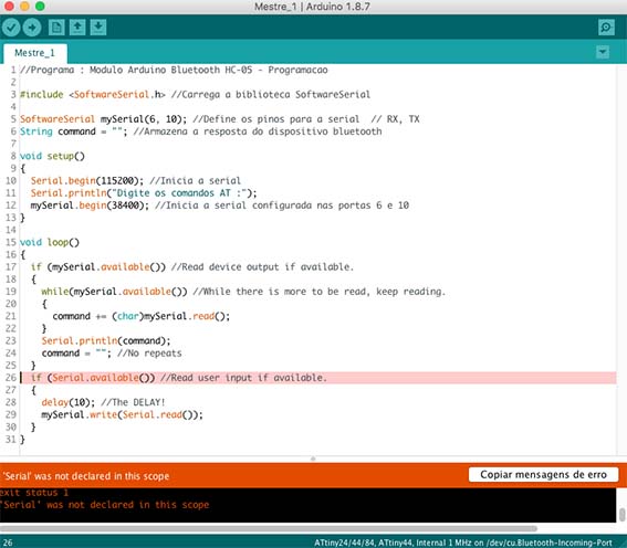
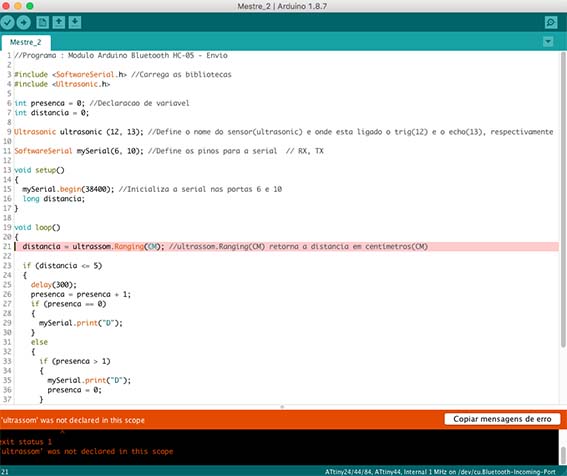
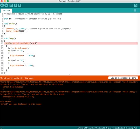
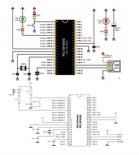
Apparently, the Attiny 44 was not recognizing the "soft serial" command embedded in the programming code. This command is used to programme the bluetooth module. It seems that the Attiny 44 does not have the library in itself for to recognize the "soft serial" command. So it seemed that to fix this problem I would have to start the board design over, thinking it with another microntroller other than the Attiny 44. One possibility would be to use the microcontroller PIC 18f4550.
Moving to Object Design:
To design the lamp itself, my initial plan was to have a cube with multiple tubes emerging from it, each one of them with a different high and a singular light bulb. My plan was to make the cube out of epoxy transparent resin, use plastic translucent tubes and have the light bulbs coming out of it. I started by experimenting with how I would cast the cube having hollow parts to stick the tubes afterwards. I did some initial attempts that did not really work well, I tried to cast a tube made out of silicon rubber OOMOO 25. My idea was that, since this material does not glue to the epoxy resin, I would be able to remove it after casting and have a hollow part to attach the tube to.
The following pictures show the attempt to cast the tube made out of silicon rubber OOMOO 25
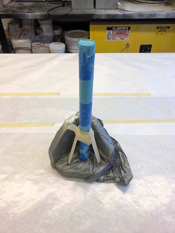
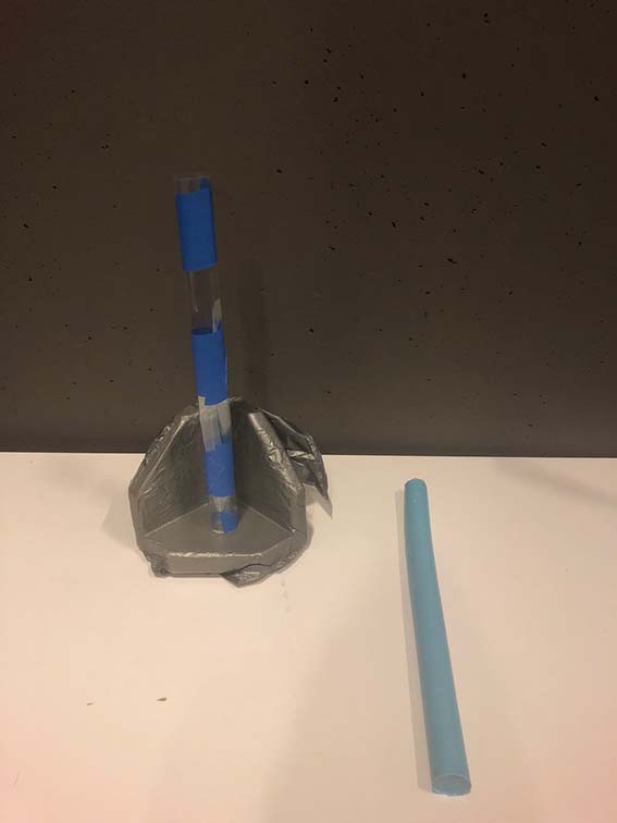
The casting itself worked pretty well, although I did not think before it would be too flexible to be used as a part of the mold.
I have done a casting test with the Crystal Clear Resin 206, this time considering to cast the tube already directly inside the cube, giving up the possibility for it to be removable. The test worked pretty well, but I found out that just using the universal releaser against the styrofoam mold was not enough to remove the casted object out of the mold.
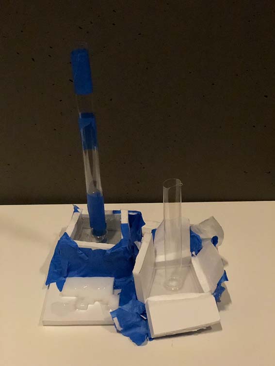
With the assistance of Smooth-On, I found out that to cast the clear resin using a styrofoam mold I would have to use two products to be able to remove the casted object. They have recommended using the Epsilon over the styrofoam surface and, once it is cured to apply the release agent, universal release. To do the final cast, in the final shape, I have designed a mold in Fusion-360 and cut it using the shop boot. I was very happy with the result of the mold, it was very stable, holding together very well and perfectly orthogonal. Unfortunately, I ended up not being able to use this mold. I realized I was running out of time to produce the final object as I have initially conceptualized it, so instead of casting the cube and having multiple tubes and light bulbs, I decided to do a more simple prototype with just one light bulb (this whole experimental process with the materials and production of the object was done before the electronics part, and the decision of using just one light bulb was actually fundamental to the electronics, since I have made a board with just one relay, which is compatible to be used with one light bulb respectively).
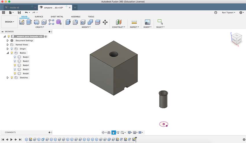
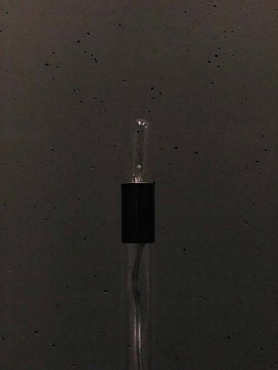
So, for the prototype, I have design two parts in Fusion 360. One of them was a much smaller cube to be the support for the tube and light, the second one was an adaptor for the light bulb socket to perfectly fit the translucent tube.
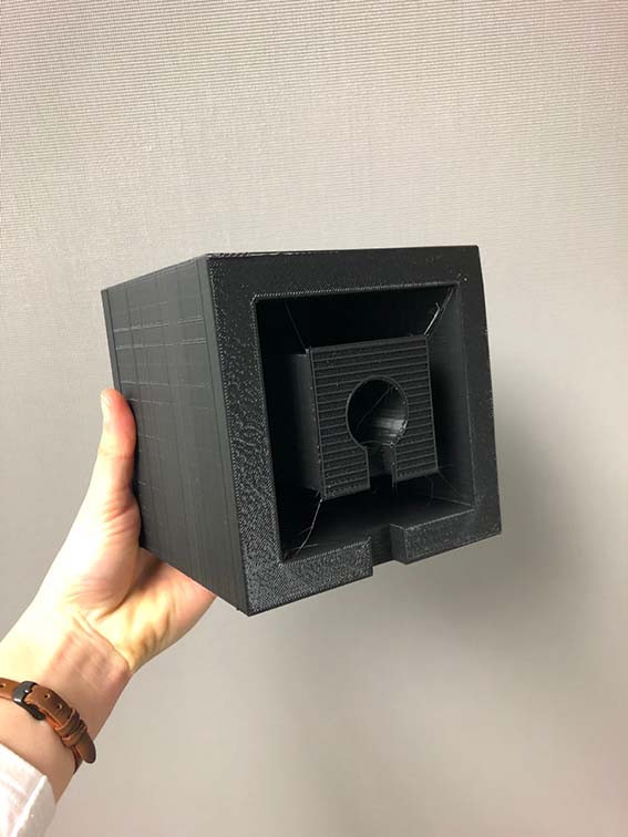
I have designed the cube with a hollow interior so that I would use less material and less time while 3D printing. It also had a trace to accommodate the electric wire that could connect the light bulb to the electronic board.
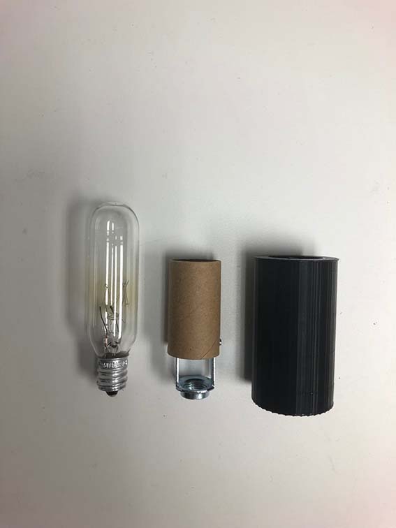
The adaptor for the light bulb socket was done in a pretty straightforward way. I used the pachometer to get the right dimensions and designed it in Fusion. However, I had to do some small adjustments to it and reprint it, it did not work at the first time, I had to adjust some dimensions.
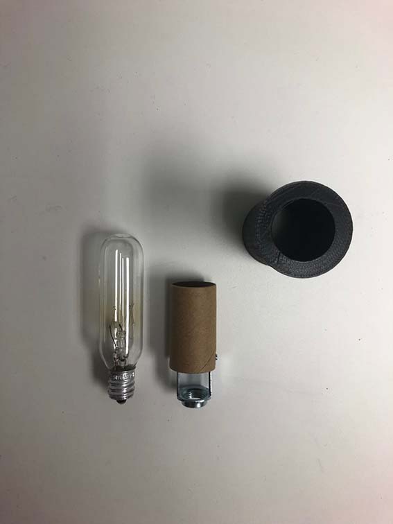
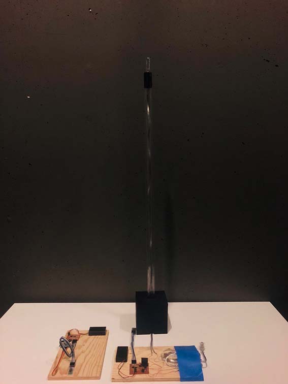
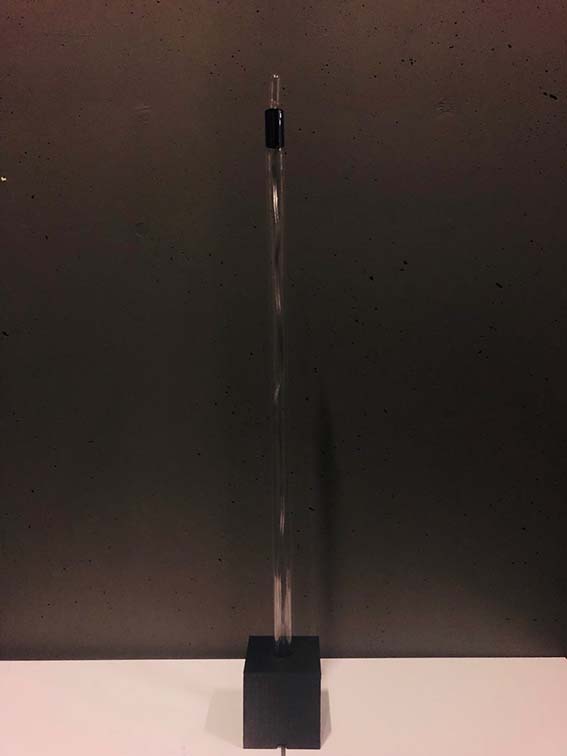
After having all the parts fitting together, I have assembled the lamp and connected it to the slave board.
Unfortunately, I ended up not having enough time to redo the board with a different design using a different microcontroller as the PIC 18f4550 and therefore did not have my project working. I believe however this would be an easy resonable fix to do with a bit more time to have it completely working.
I would say I spend between 60 -80 dollars to develop this project.
For my final project, I decided to make a lamp that I could turn on and off remotely.
My idea was to conceptualize the project from devices we have learned in class. Therefore, I decided to use an Ultrasonic Sensor as the trigger for turning the light on and off, and a Bluetooth module HC - 05 to transmit the signal from the sensor and allow the procedure to operate remotely.
As a starting point, I have visited some tutorials as well as other projects that have used Bluetooth sensor to remotely activate different mechanisms, like the following:
http://fab.cba.mit.edu/classes/863.17/CBA/people/oscarrosello/index.html#portfolioModal11
https://www.filipeflop.com/blog/controle-modulo-rele-arduino/
https://portal.vidadesilicio.com.br/hc-sr04-sensor-ultrassonico/
https://www.arduinoecia.com.br/2016/11/digispark-attiny85-ide-arduino.html
I haven't found a reference using exactly the same devices I choose to work with, however, these tutorials were good starting points to know to start thinking about the project and to understand deeper the functionality of each of its parts separately. To start thinking about the project, I knew I would need 2 different boards, both with separate energy supply, one connected to the lamp and the other independent and transportable, to be used remotely.
The basic operation for this system would be:
Ultrassonic sensor captures change of distance of objects in front of it, for example, a hand moving closer to the sensor. This movement- change of distance- is captured by the sensor, which will send a signal to the microcontroller of the correspondent board, which by its turn communicates with the master bluetooth module, which will send a signal to the slave bluetooth module, which is connected to the second board, directly attached to the lamp.
Knowing the most basic procedure and components I would have to have to make the board work, I started to research deeper how I would connect them in a board and which other complementary basic components I would need.
With the help from Natan Monticeli, a guru in electronics, I could trouble shoot the board design and the connection between the components to have the board working. I have then done the design in eagle for each of the boards, master and slave.
Since I have done a just one-sided board (with all the components soldered at the same side), it was pretty hard to draw all the traces without jumpers, so I ended up having many (!!!) of them. After milling and soldering the slave board, I have realized that I somehow forgot to draw one trace connecting one of the resistors to the microcontroller, and I ended up doing a big jumper to connect them (what was certainly not ideal, but solved the problem)
Both boards worked when I connected them to my USBtiny programmer, both Bluetooth devices lighted up. I had both boards connected to the external battery, both with 3,5V (ideally they would be connected to 5V - but I used rechargeable batteries with 1,5V each).
With the boards done I have started the programming part. I used a basic programming code as a reference, and with the help of a programming, guru changed it to correspond to the needs of the project.
The basic programming concept was to programme the Bluetooth module form the master board as the signal 'sender' and the Bluetooth module from the slave board as the 'receiver'.
For that, two separate programming steps should be done in the master module. The first step was to "lock" the key pin of the Bluetooth module, transforming it into only a signal emitter. The second step is to programme it to actually send the signal and to connect to the second Bluetooth module. This code will teach the module how it should convey a message to the other Bluetooth module. This step happens through a 'library' called software serial. This library will enable communication. Beyond the libraries, the code also establishes variables for the ultrasonic sensor, which will establish through a predefined distance, if the lamp should turn on or off. If the sensor detects movement from a change of distance just one time, it sends the turn on on code (L). If it detects a second movement, it recongnizes the second one as a turn f and it sends the code (D). If there is no change of distance recognized by the sensor, it understants as having no presence and it sends the code (D) to the slave board, also keeping it turned off.
The code used for the slave board, was just to make it identify which information it should be receiving from the master board: code (L) - turn on / code (D) turn off.
The following codes were the codes used to try to programme the boards.
Master 1:
//Programa : Modulo Arduino Bluetooth HC-05 - Programacao
#include
SoftwareSerial mySerial(6, 10); //Define os pinos para a serial // RX, TX String command = ""; //Armazena a resposta do dispositivo bluetooth
void setup()
{
Serial.begin(115200); //Inicia a serial
Serial.println("Digite os comandos AT :");
mySerial.begin(38400); //Inicia a serial configurada nas portas 6 e 10
}
void loop()
{
if (mySerial.available()) //Read device output if available.
{
while(mySerial.available()) //While there is more to be read, keep reading.
{
command += (char)mySerial.read();
}
Serial.println(command);
command = ""; //No repeats
}
if (Serial.available()) //Read user input if available.
{
delay(10); //The DELAY!
mySerial.write(Serial.read());
}
}
Master 2
//Programa : Modulo Arduino Bluetooth HC-05 - Envio
#include
#include
int presenca = 0; //Declaracao de variavel
int distancia = 0;
Ultrasonic ultrasonic (12, 13); //Define o nome do sensor(ultrasonic) e onde esta ligado o trig(12) e o echo(13), respectivamente
SoftwareSerial mySerial(6, 10); //Define os pinos para a serial // RX, TX
void setup()
{
mySerial.begin(38400); //Inicializa a serial nas portas 6 e 10
long distancia;
}
void loop()
{
distancia = ultrassom.Ranging(CM); //ultrassom.Ranging(CM) retorna a distancia em centímetros(CM)
if (distancia <= 5)
{
delay(300);
presenca = presenca + 1;
if (presenca == 0)
{
mySerial.print("D");
}
else
{
if (presenca > 1)
{
mySerial.print("D");
presenca = 0;
}
else
{
mySerial.print("L");
}
}
}
}
Slave
//Programa : Modulo Arduino Bluetooth HC-05 - Recepcao
char buf; //Armazena o caracter recebido ("L" ou "D")
void setup()
{
pinMode(12, OUTPUT); //Define o pino 12 como saida (Lampada)
Serial.begin(9600);
}
void loop()
{
while(Serial.available() > 0)
{
buf = Serial.read();
if (buf == 'L')
{
digitalWrite(12, HIGH);
}
if (buf == 'D')
{
digitalWrite(12, LOW);
}
}
}
However I experienced some issues while doing it. keep getting an error saying that the serial was not declared in this scope:
Apparently, the Attiny 44 was not recognizing the "soft serial" command embedded in the programming code. This command is used to programme the bluetooth module. It seems that the Attiny 44 does not have the library in itself for to recognize the "soft serial" command. So it seemed that to fix this problem I would have to start the board design over, thinking it with another microntroller other than the Attiny 44. One possibility would be to use the microcontroller PIC 18f4550.
Moving to Object Design:
To design the lamp itself, my initial plan was to have a cube with multiple tubes emerging from it, each one of them with a different high and a singular light bulb. My plan was to make the cube out of epoxy transparent resin, use plastic translucent tubes and have the light bulbs coming out of it. I started by experimenting with how I would cast the cube having hollow parts to stick the tubes afterwards. I did some initial attempts that did not really work well, I tried to cast a tube made out of silicon rubber OOMOO 25. My idea was that, since this material does not glue to the epoxy resin, I would be able to remove it after casting and have a hollow part to attach the tube to.
The following pictures show the attempt to cast the tube made out of silicon rubber OOMOO 25
The casting itself worked pretty well, although I did not think before it would be too flexible to be used as a part of the mold.
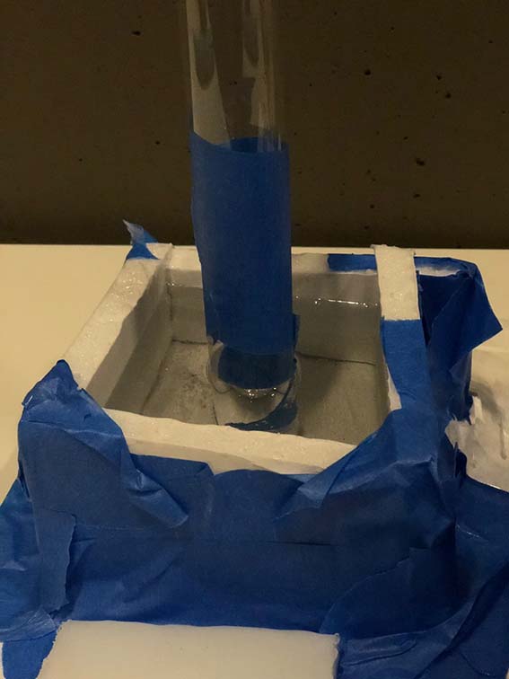
I have done a casting test with the Crystal Clear Resin 206, this time considering to cast the tube already directly inside the cube, giving up the possibility for it to be removable. The test worked pretty well, but I found out that just using the universal releaser against the styrofoam mold was not enough to remove the casted object out of the mold.
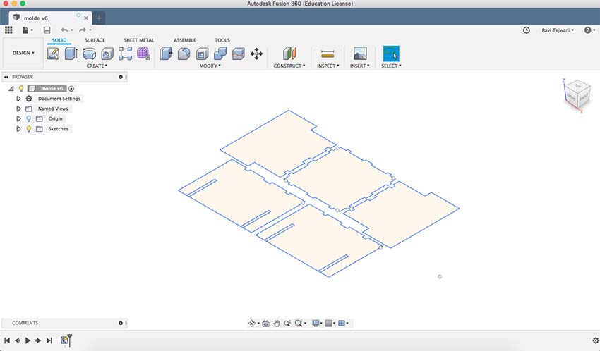
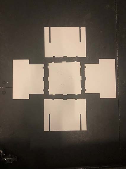
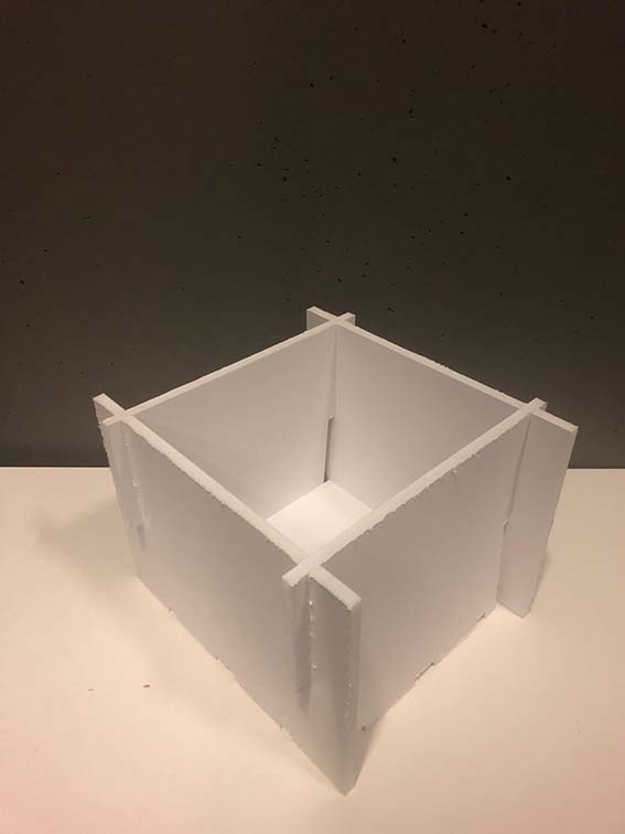
With the assistance of Smooth-On, I found out that to cast the clear resin using a styrofoam mold I would have to use two products to be able to remove the casted object. They have recommended using the Epsilon over the styrofoam surface and, once it is cured to apply the release agent, universal release. To do the final cast, in the final shape, I have designed a mold in Fusion-360 and cut it using the shop boot. I was very happy with the result of the mold, it was very stable, holding together very well and perfectly orthogonal. Unfortunately, I ended up not being able to use this mold. I realized I was running out of time to produce the final object as I have initially conceptualized it, so instead of casting the cube and having multiple tubes and light bulbs, I decided to do a more simple prototype with just one light bulb (this whole experimental process with the materials and production of the object was done before the electronics part, and the decision of using just one light bulb was actually fundamental to the electronics, since I have made a board with just one relay, which is compatible to be used with one light bulb respectively).
So, for the prototype, I have design two parts in Fusion 360. One of them was a much smaller cube to be the support for the tube and light, the second one was an adaptor for the light bulb socket to perfectly fit the translucent tube.
I have designed the cube with a hollow interior so that I would use less material and less time while 3D printing. It also had a trace to accommodate the electric wire that could connect the light bulb to the electronic board.
The adaptor for the light bulb socket was done in a pretty straightforward way. I used the pachometer to get the right dimensions and designed it in Fusion. However, I had to do some small adjustments to it and reprint it, it did not work at the first time, I had to adjust some dimensions.
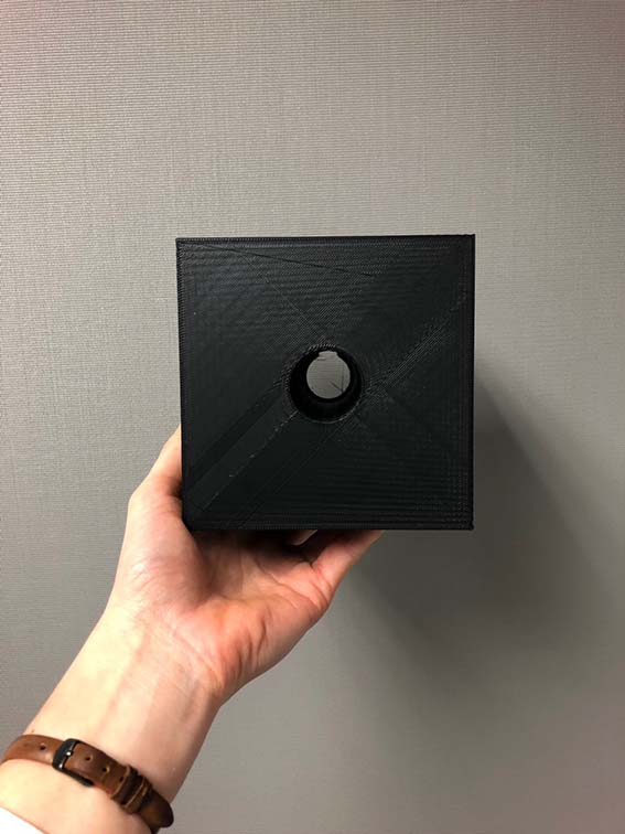
After having all the parts fitting together, I have assembled the lamp and connected it to the slave board.
Unfortunately, I ended up not having enough time to redo the board with a different design using a different microcontroller as the PIC 18f4550 and therefore did not have my project working. I believe however this would be an easy resonable fix to do with a bit more time to have it completely working.
I would say I spend between 60 -80 dollars to develop this project.