this weeks assignment: redraw the echo hello-world board, add (at least) a button and LED (with current-limiting resistor) check the design rules, make it, and test it
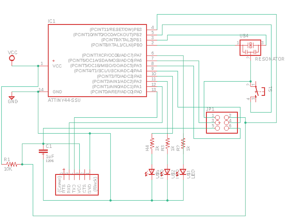
using the echo hello-world board as a starting point, i started my journey into the circuit design needed to add a button and an LED. i played with Eagle a bit before, but that didn't stop me from running into a few errors in the design process.
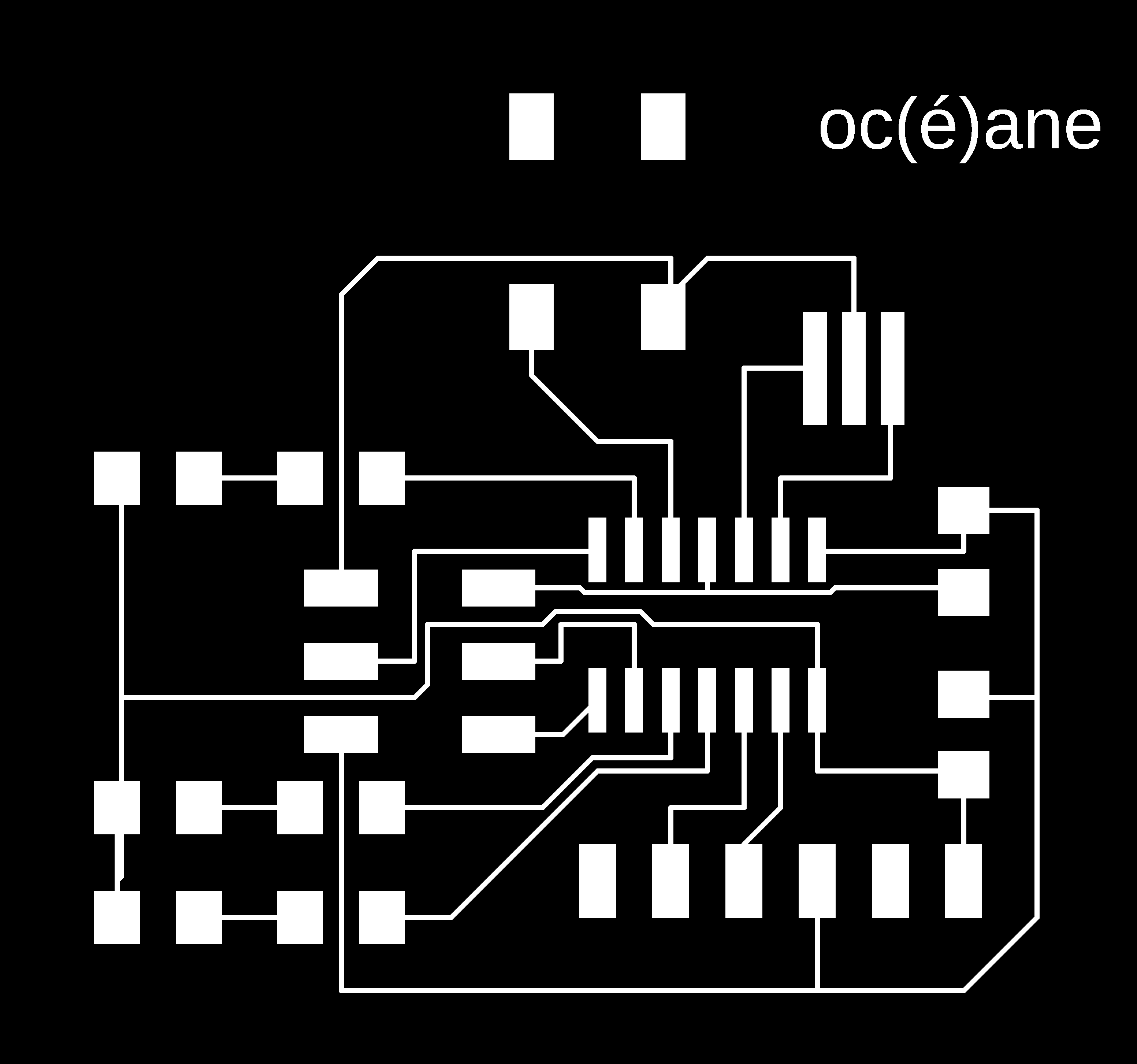
in order to convert the board file into a png -> Adobe Illustrator -> CorelDraw on the vinyl cutter, Tomàs our TA, gave us the following tips when exporting the image in Eagle...
1) (make sure you're in the command line!)for the top trace layer:
ratsnest->display->none->top->export->image->dpi 1000, monochrome checked
2) for the board outline: ratsnest->display->none->dim->export image dpi 1000, monochrome checked
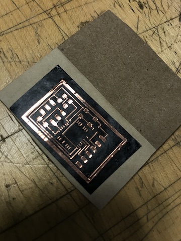
time for the vinyl cutter! some tips for future users of the Roland while attempting to cut out fine lines on to the copper substrate:
1) I tried to use the copper adhesive on top of vinyl, but that was a no-go. although it is possible (see inspiring work done by Vanessa), i couldn't adjust the tip low enough that it would cut through both the vinyl and copper without lowering it too far that it was cutting into the clear mylar (aka, acetate, or projector paper).
2)clean the tip of the cutter before you begin! previous use will "clog" up the tip with vinyl and copper, which makes it very easy to ruin the delicate carvings in the copper
3) when setting up, try your best to keep the acetate flat and tyhe copper layer as smooth as possible upon application. this is easier said than done, but it is possible!
progrmaming this board took more time in just downloading all of the required drivers (avr-gcc, FTDI drivers, serialpy etc). there was a bit of confusion, but with some help from Tomàs the TA, all was well...sort of. To make sure the board was properly soldered, i checked to see the 5v flowing from the GND (pin 1) to Vcc (pin 3) ont he FTDI headers. The general set up was:
(for the new board) FTDI header -> USB -> USB-C hub (i have a 2018 Mac)
(for the programmer) USB -> USB-C hub. the FTDI header came up as "tty.usbserial-AC01YB7N". i used "ls /dev" to check on this labeling.
everything uploaded properly after obtaining avr-gcc using homebrew install (since MacOS doesn't have a native package manager). After that i
1) made the .hex file using the old programmer "make -f hello.ftdi.44.echo.c.make"
2) and then turned the new board into a programmer with "make -f hello.ftdi.44.echo.c.make program-usbtiny"
3) finally, in order to run the term.py file Neil provided, you must first "pip install pyserial" upon running "python term.py /dev/tty.usbserial-AC01YB7N 115200", i was presetned with the expected widget where one can enter in text. unfortunately, it kept freezing on me and i'm currently working out the kinks on that end. updates soon to follow!
![]()