this week's assigment: read a microcontroller data sheet program the ATTiny44 board to do something, with as many different programming languages and programming environments as possible
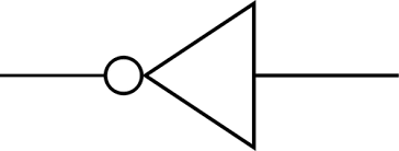
a couple weeks ago, i dove into creating circuits with the vinyl cutter, only to fail (wonderfully, i should say, because i learned a lot!). i came back this week with renewed vigor to approach my friend the vinyl cutter. this time, i was ready with a solid substrate: recycled plywood. the steps taken to get to the picture below were very similar to week 4, except this time i had superglued the acetate layer (where the circuit is adhered) to the recycled plywood.
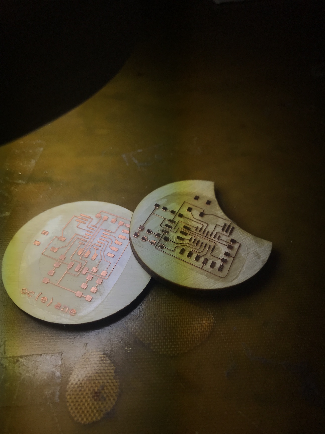
i made two for no particular reason other than that sometimes soldering is fun and you win...but usually soldering is still fun and you lose. plus, its good practice!
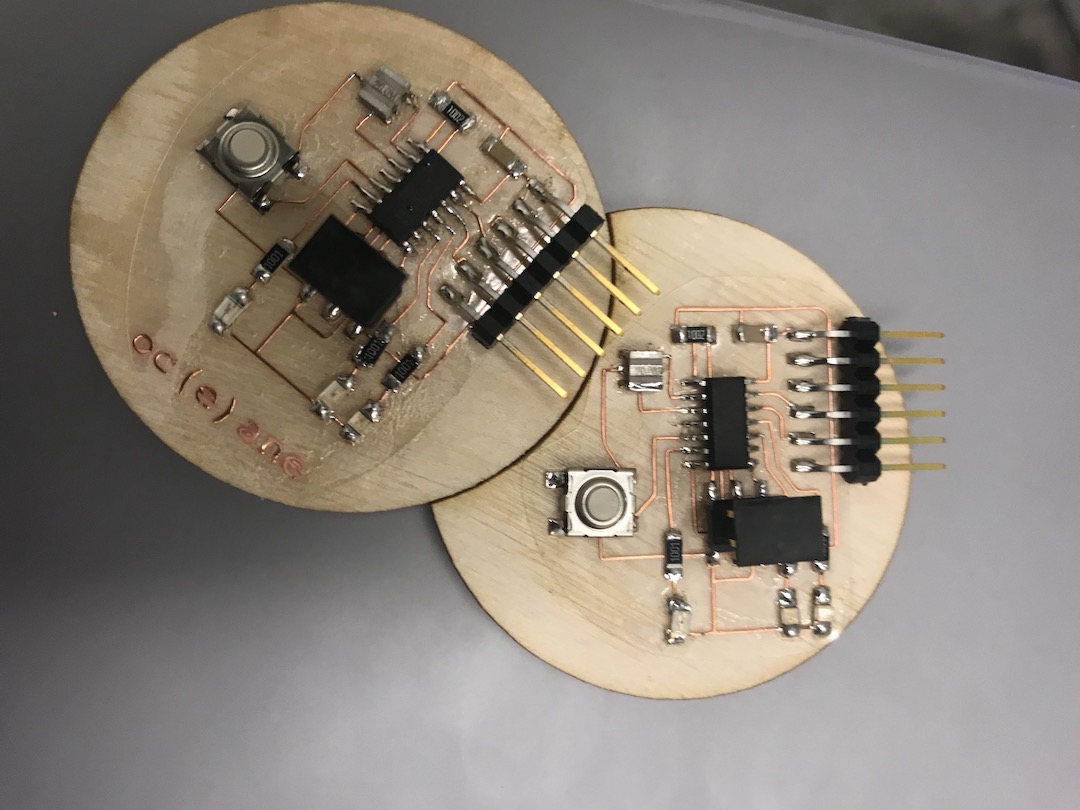
time to upload code!...err almost. after uploading (i'll go over how this was done below), i spent a better half of an hour trying to figure out why my LEDs wouldn't blink after runnig the BLINK LED C program given to us by Niel. turns out you shouldn't solder late at night kids, because then you solder your LEDs on backwards. note to future self/anyone crazy enough to read this: the green bar on the sm LED should ALWAYS face GND. and it would also be good to check that you did that correctly before pouring resin over your board. luckily, i had soldered on the LEDs properly on the other board, so i went to work programming the button to cycle between two LEDs
//in this program, the goal is to get a LED to set HIGH (remain lit)
//from here, we'll add another LED and the button functionality.
//this was adpated from Erik's BLINK code...thanks Erik!
#include
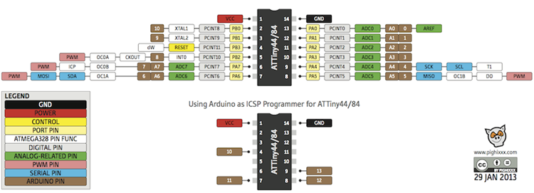
#define led_pin (1 << PA2) //pin 11 according to the ATTiny44 pinout
int main(void) {
// Configure led_pin as an output.
DDRA |= led_pin;
// Set led_pin high.
PORTA |= led_pin;
// Nothing left to do, so just stay in a loop.
while (1) {}
return 0;
}
this worked! so i continued to build out the code. i'll let the comments take over from here!
//this code was built for the ATTiny 44 to make 2 LEDs blink in sequence
//By Océane Boulais for HTMAA 2018

#include

#define led_pin1 (1 << PA2) //pin 11
#define led_pin2 (1 << PA3) //pin 10
#define button_pin (1 << PB2) //pin 5

int main(void) {
    // Configure led_pin1 as an output.
    DDRA |= led_pin1;
    // Configure led_pin2 as an output.
    DDRA |= led_pin2;
    // Configure button_pin as an input.
    DDRB &= ~button_pin;
    // Activate button_pin's pullup resistor.
    PORTB |= button_pin;

    // Set led_pin1 high.
    PORTA |= led_pin1;
      // Set led_pin2 high.
    PORTA |= led_pin2;

    // start the loop!
    while (1) {
        // Turn on the LED1 when the button is pressed.
        if (PINB & button_pin) { //check the bits in register PINB
            // Turn off the LED1, turn on LED2.
            PORTA &= ~led_pin1; //turning off LED1. ANDing (&=) sets the bits in register PORTA to 0
            PORTA |= led_pin2; // turning on LED2. ORing (|=) sets the bit to led_pin2 value

        } else {
            PORTA &= ~led_pin2; //turning off LED2.
            PORTA |= led_pin1; // turning on LED1. ANDing (&=) sets the bits in register PORTA to 0
        }
    }

    return 0;
}