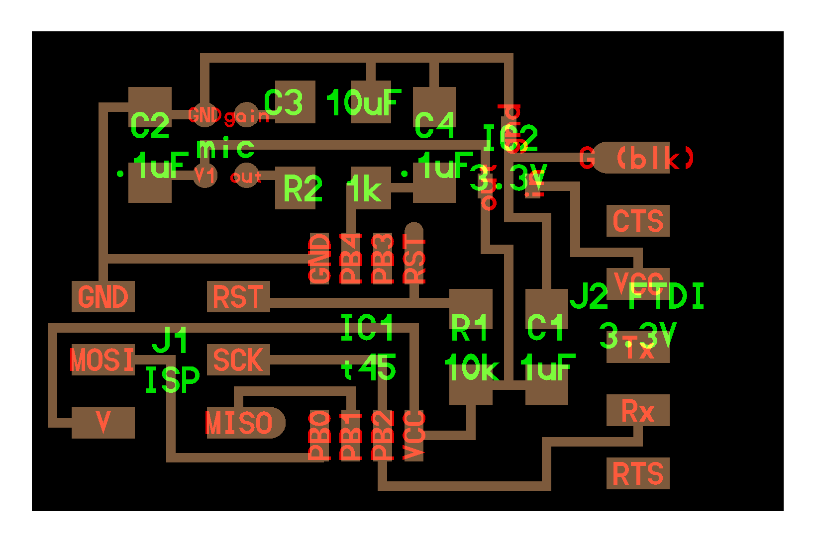
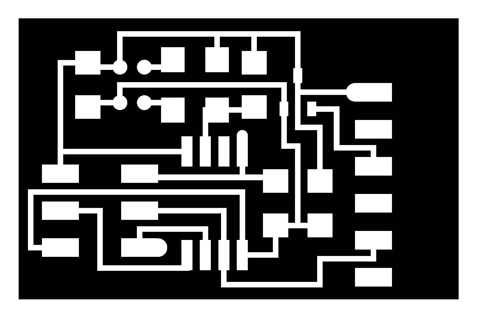
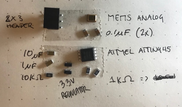
this week's assigment: measure something: add a sensor to a microcontroller board that you have designed and read it. Using the ATTiny45, the goal is to program the board to listen for sounds and output a voltage signal that i can (hopefully) differerntiate from the noise
couple weeks ago, i dove into creating circuits with the vinyl cutter,and decided to continue being friends with the vinyl cutter. this week's design focus: master epoxy resin pouring and get a good signal read from the analog mic
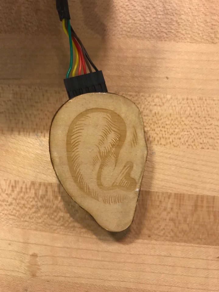
i found an ear outline online, fixed it up a bit in CorelDraw and cut a few ears out on the laser cutter. the acetate/vinyl circuit was then super glued to the wood.
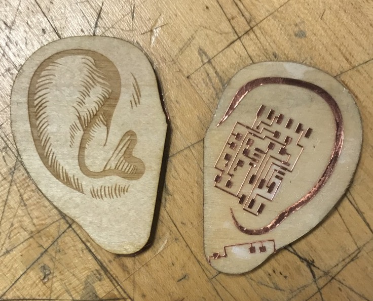
...on to the soldering and testing before epoxy resin pouring
...i did continuity testing on the pins of the ATTiny45 to make sure everything was properly soldered, and continued unto the pouring of the epoxy (also not a system i've yet to streamline). NOTE: the FTDI headers require too much force to be applied to the board and the vinyl circuit just wants to rip away, so i poured a little bit of epoxy on the header pins to keep the FTDI header pinned to the board for testing
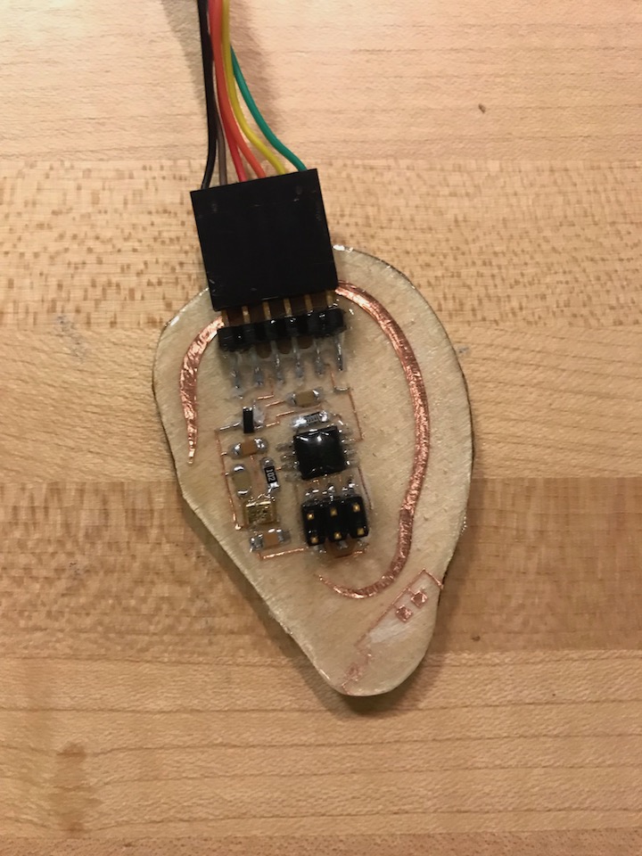
using the files provided by Neil, i began by generating my .hex file with the .c and makefile and tried uploading it to the earboard...which is when i got the dreaded rc = -1 from avrdude. upon a quick post-resin pouring inspection of the board with the DMM, i found that the FTDI GND pin was no longer connected to the ATTiny45 GND pin. my hypothesis is that there was some user error (me) in handling the board and the delicate connection to the GND pin from the FTDI header was ripped away during testing. it is difficult to see on the board because of some trapped air bubbles, but this seems to be the case. *sigh* i plan on using this board for my final project, so i will most likely try this exact same board again, but perhaps on the PCB mill for a sturdier substrate to test on, and then move back to the vinyl cutter.

//useful note to self when making .hex file -> uploading to the micro
1. rename hello.whatever.c.make into just makefile
2. run make
3. sudo make program-usbtiny
4. sudo make program-usbtiny-fuses
//this is just a useful script to create a python environment in Conda once you're ready to run your .py program
conda create --name sound
source activate sound
conda install numpy
conda install pyserial
python hello.SPU0414HR5H.py /dev/cu.usbserial-AC01YB7N