this week's assigment: add an output device to a microcontroller board you've designed, and program it to do something. for my final project, i need a breakout board that controls intensity of a strip of addressable LEDs that will be triggered by sound. i figured a great way to see test out the LED control is by building a pair of litty sneaks for the next 99fridays (a lovely monthly festivity that happens at the Media Lab)
let's chat about circuit design. the desired amount (length) of addressable LEDs will deteremine how much power you need to light up segments of the LED strip. I'm using these adhesive backing LEDs from LED Wholesalers. Looking at the specsheet, when at full brightness, there is a current draw of 20mA per section where each section has 3 LEDs. from fitting the LEDs around the back of my shoe, i used up 6 segments for a total of 120mA. i found a 3.7V | 1200mAh LiPo battery pack floating around. at a consumption of 120mA, the battery should last a around 10 hours...definitely enough time to scorch the dance floor.
a helpful tip also is to cover the solder connections where wires for the battery and LED strip go with hot glue for strain relief. don't forget your current-limiting resistor ahead of the LED strip to avoid blowing out a portion of the circuit! Use Ohm's law to calculate the required resistance from a what we assume to be a 3.7V 1200mA battery.
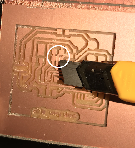
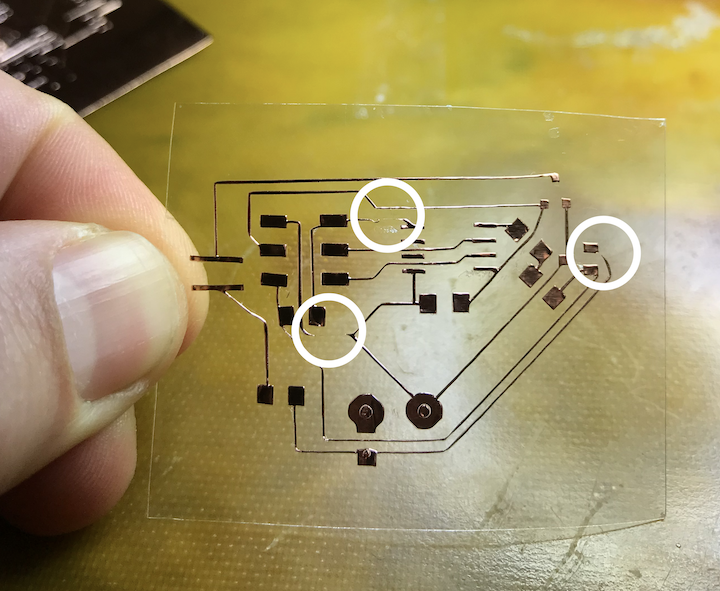
aaaannnnd the failures begin...i had forgotten why i disliked the Roland, since I'd been happily distracted by the vinyl cutter. the reason for the machine swap is because although the vinyl cutter is a lovely tool, there are many potential pitfalls along the way and i figured the LED strip would move around a bunch, so why not have a sturdy substrate for the first round?
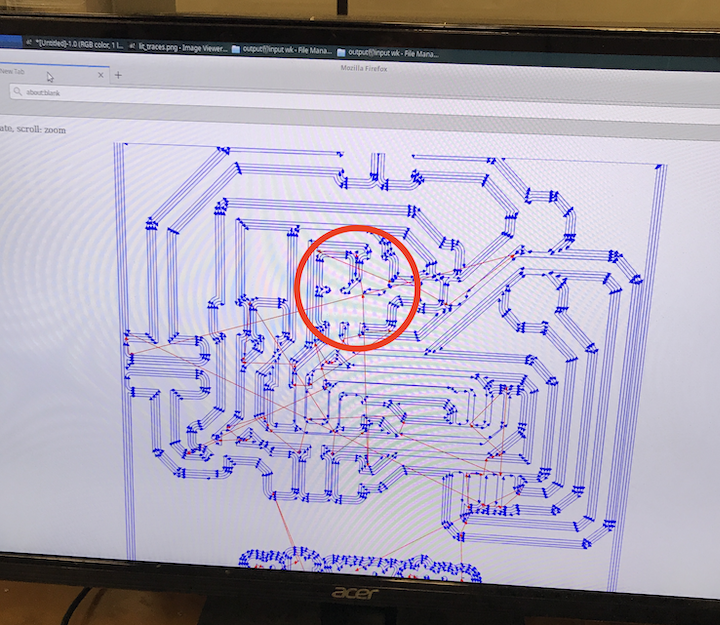
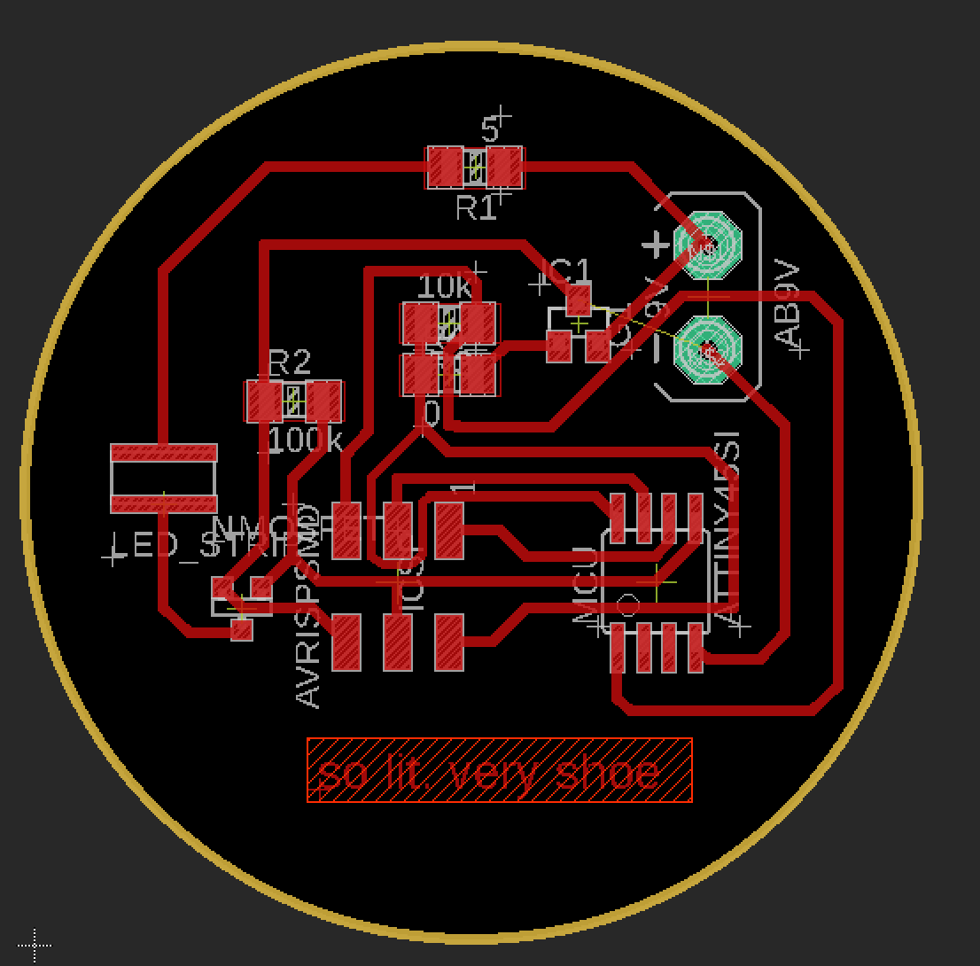
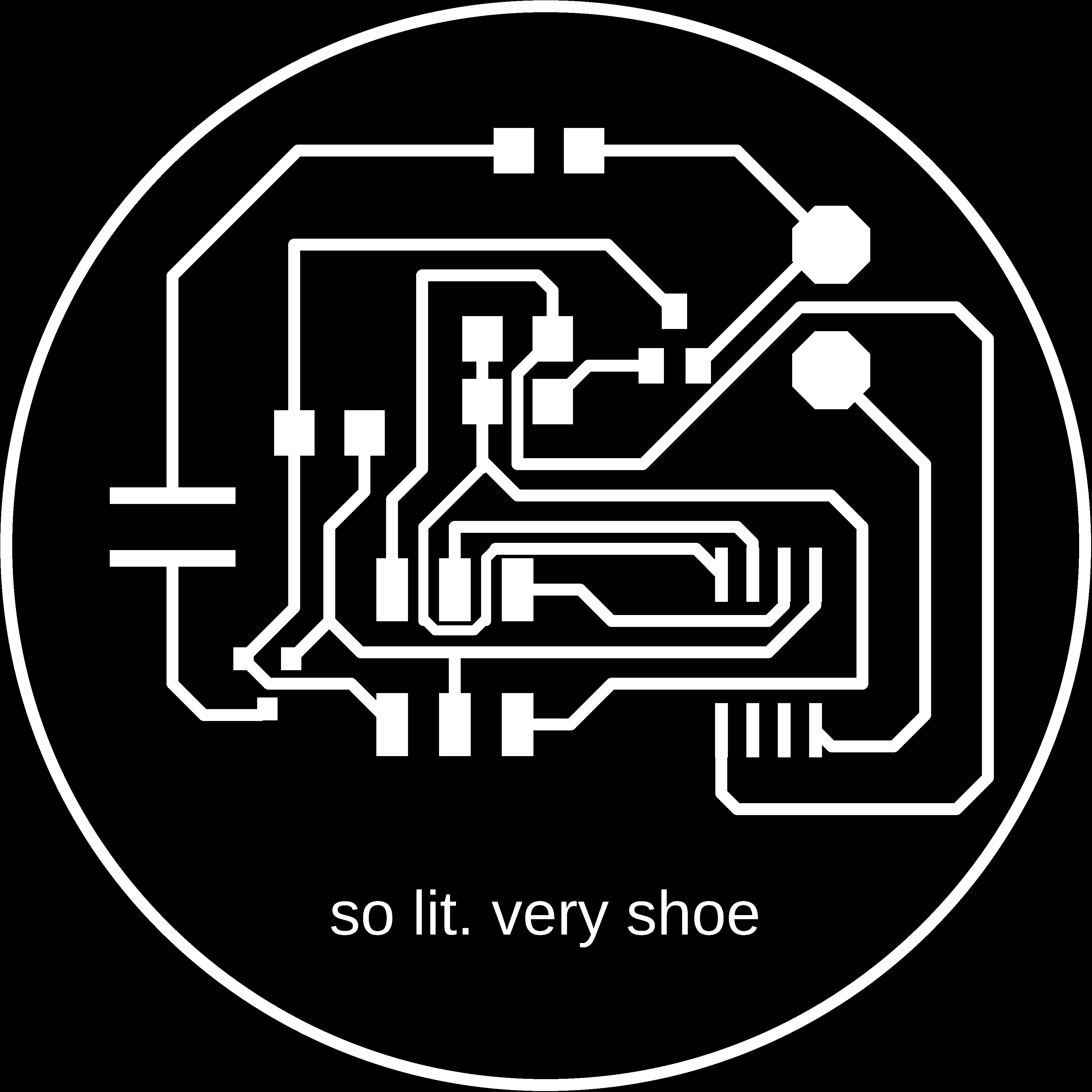
i was experimenting with super thin wires (i changed the orientation of a few components trying to optimize the least amount of flex on the LED strip side of the board) since my goal was to create something to go on the back of a patch for a pair of converse, where the LiPo battery pack would also live.


i have some major fixes to make this week going forward! this past week i distracted with the design of the final project structure (no excuses though...i know)
//code that i will be implementing from Bldr.com
/////////////////////////////////////////////////////////////////
//©2011 bildr
//Released under the MIT License - Please reuse change and share
//Simple code to output a PWM sine wave signal on pin 9
//////////////////////////////////////////////////////////////////

#define fadePin 0

void setup(){
  pinMode(fadePin, OUTPUT);
}

void loop(){
  for(int i = 0; i<360; i++){
    //convert 0-360 angle to radian (needed for sin function)
    float rad = DEG_TO_RAD * i;

    //calculate sin of angle as number between 0 and 255
    int sinOut = constrain((sin(rad) * 128) + 128, 0, 255);

    analogWrite(fadePin, sinOut);

    delay(15);
  }

}