sensing acceleration
individual assignment: measure something: add a sensor to a microcontroller board that you have designed and read it
group assignment: probe an input device’s analog levels and digital signals
In order to contribute to my final project, I decided to use an accelerometer sensor that I could attach to the helmet in order to sense the acceleration induced by the motor mechanism.
acceleration, orientation, rotation resources from Neil:
However, I decided to challenge myself to design my own board–one that interfaces the ADXL343 Accelerometer with the ATTiny44 that we used for the echo hello world board.
Components:
- 1 x ATTiny44
- 3 x 10k ohm resistors
- 1 x 100 nF capacitor
- 1 x 1 uF capacitor
- 1 x 3.3 V regulator
- 1 x ADXL343 accelerometer
- 1 x ISP
- 1 x FTDI
In order to create my schematic, I could not find my accelerometer in existing parts library, so I downloaded it from the DigiKey Ultra Librarian and loaded it by following these instructions for Eagle.
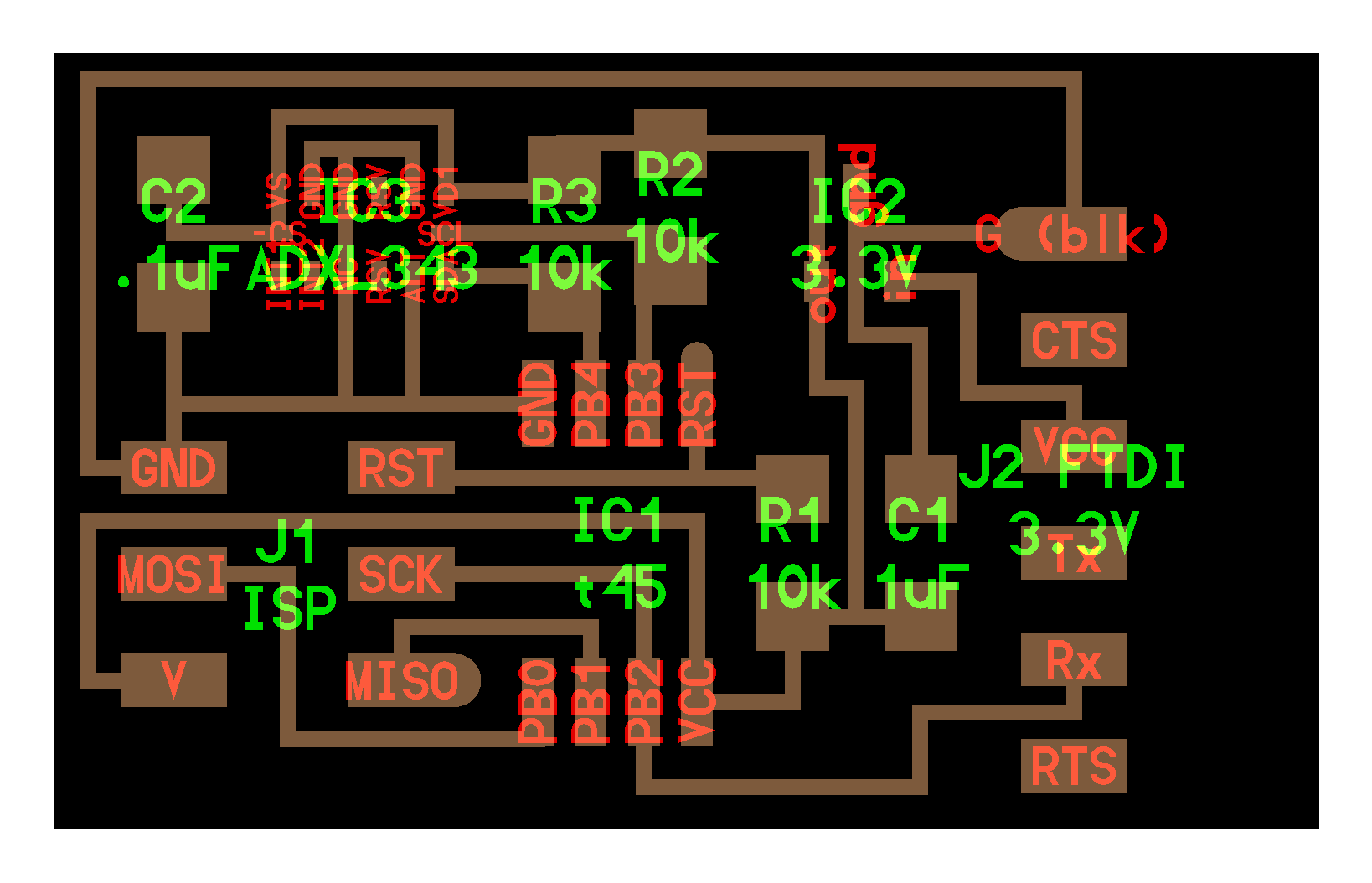
I designed the board using Eagle and wanted to see how I could create an aesthetic. Inspired by the superhero comic book theme of my final project, I thought Captain America’s shield would be a great PCB to make.
schematic:

- 5:15 –> 6:09 pm
- i wanted to make sure that the SDA and SCL are connected properly. checked out this sparkfun tutorial
- note: in my board I used pa7 instead of pb3 -> pa7 and pb2 instead of pb4.
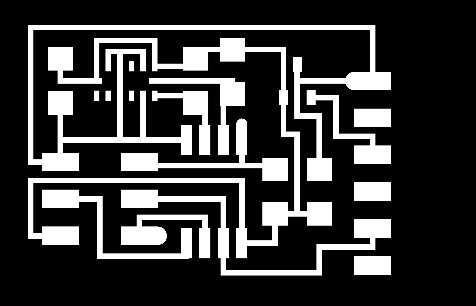
completed board design:

- 6:30 to 9 pm
- As I was routing, I had a lot of trouble connecting components when creating explicit traces for ground. After setting design rules, I attempted autorouting multiple times (with the locations laid out at different parts). Eagle had a 80-90% success rate with 3-4 vias that required traces to go on another layer (or the botom of the board). For the purpose of my manufacturing process, I wanted the entire circuit to lay on the top layer. If the autorouting could only get this far, how far could I get?
- I channeled my frustration into rotating the components to be at unconventional angles and spent time routing the components by hand.
- upon export as png, select monochrome and 1000 dpi. Take note of the size of the image (2649 x 2337) because this will help us with the next point.
- resize image to size specified in export window since, on Mac, Eagle exports at twice the size.
- fill in the outside with white so that path calculated by mods is correct.


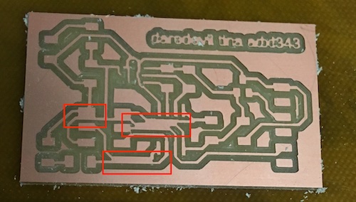
milling: The pads under the accelerometer are extremely small. With an offset of 4 and endmill size of 1/64th inch (.3968 mm), the calculated path does not cut the pads for the accelerometer.

suggested workarounds:
- use a smaller endmill
- apply a mask to that part of the trace, run the rest of the job with the offset of 4, and then mill only the part where the accellerometer with an offset of 1.
I didn’t get a chance to apply these workarounds but hope to soon!
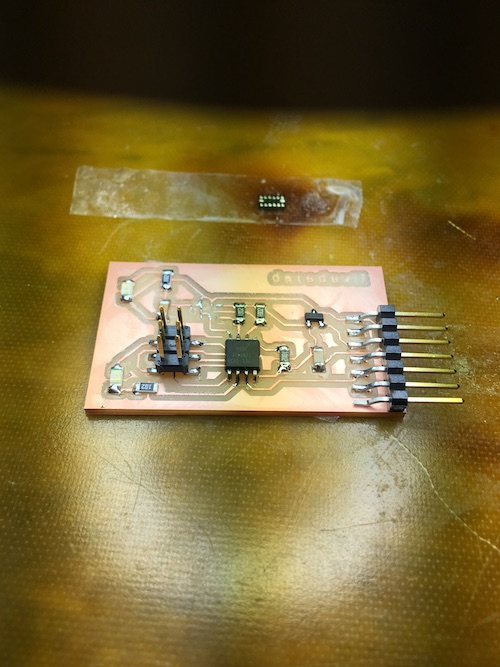
Instead, I decided to use the example info provided by Neil and made this board:

programming:
When I was programming the board, I ran into trouble
  quacht@bish-whet~/Documents/Course/htmaa/content/sensor/code: sudo make -f hello.ADXL343.make program-ice
  Password:
  avr-objcopy -O ihex hello.ADXL343.out hello.ADXL343.c.hex;\
     avr-size --mcu=attiny45 --format=avr hello.ADXL343.out
  AVR Memory Usage
  ----------------
  Device: attiny45

  Program:    1018 bytes (24.9% Full)
  (.text + .data + .bootloader)

  Data:          0 bytes (0.0% Full)
  (.data + .bss + .noinit)


  avrdude -p t45 -P usb -c atmelice_isp -U flash:w:hello.ADXL343.c.hex

  avrdude: stk500v2_command(): command failed
  avrdude: bad response to AVR sign-on command: 0xa0
  avrdude: Target prepared for ISP, signed off.
  avrdude: Now retrying without power-cycling the target.
  avrdude: stk500v2_command(): command failed
  avrdude: bad response to AVR sign-on command: 0xa0
  avrdude: Target prepared for ISP, signed off.
  avrdude: Now retrying without power-cycling the target.
  avrdude: stk500v2_command(): command failed
  avrdude: bad response to AVR sign-on command: 0xa0
  avrdude: Target prepared for ISP, signed off.
  avrdude: Now retrying without power-cycling the target.
  avrdude: stk500v2_command(): command failed
  avrdude: bad response to AVR sign-on command: 0xa0
  avrdude: Target prepared for ISP, signed off.
  avrdude: Now retrying without power-cycling the target.
  avrdude: stk500v2_command(): command failed
  avrdude: bad response to AVR sign-on command: 0xa0
  avrdude: Failed to return from debugWIRE to ISP.
  avrdude: initialization failed, rc=-1
           Double check connections and try again, or use -F to override
           this check.


  avrdude done.  Thank you.

  make: *** [program-ice] Error 1
I debugged my board and realized that the voltage difference between ground and the output of the voltage regulator is 0V, so there is a short somewhere in the circuit… probably due to a solder bridge. I have yet to debug the board.
Update (11/25/18)
I found that a previous student used the same accelerometer and hope that I can learn from their experience
- “To add the sensor component on the PCB I had to manually create a footprint changing the pads so that they could be milled with a 1/64 tool, that is 0.4mm distance between pads.”
- TODO: eagle tutorial for adding footprints
I am working on a breakout board right and in making it and taking a better look at the datasheet for the accelerometer, I see that the power i’ve been supplying is too high! I need V_DD and V_S to be at most 3.3 V… not 5V.
Update (12/07/18)
I will be finishing this assignment for my final project.
Update (12/10/18)
I’m creating a board that is much like Neil’s except that it has lights to visualize messages being sent and also an led for showing that the board is powered.
Coming back to project… rethinking system integration and project management. I still have a lot to do with testing parts of the system and iterating.
Today, I need to
- make and program accelerometer pcb
- 11:30-1:30 schematic and layout took
- 4:30 setup the machine + job using mods
- 4:41-4:53, 5pm run trace (2 times) (130,10), (130,49)
- 5:15-5:23 cut outlines
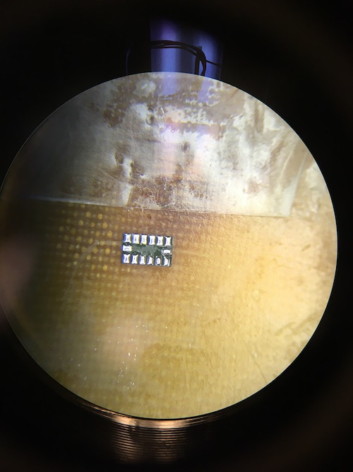
- 5:30-6:00 practice accelerometer
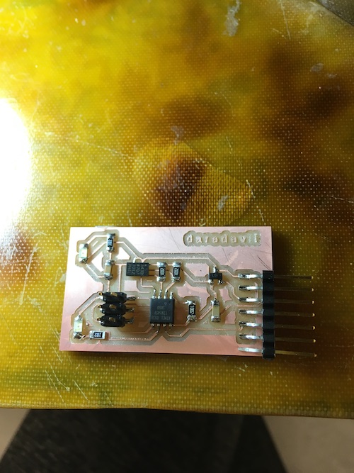
- 6:04 stuff the rest; ran into trouble actually soldering the accelerometer, incrementally soldered and tested programming my board
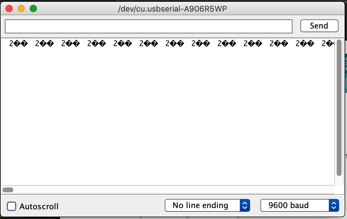
- MIDNIGHT :( programming successful even w/ accelerometer soldered on, but not receiving anything from the board over serial (using Neil’s program to visualize the acceleration data).
- 30 minutes debugging, got advice to connect to the component via wires, stopped because it was sketchy.
- modify design and 3D print the servo motor mounts to connect to the helmet
Update (12/11/18)
- [] finish accelerometer board + connect to interface
- met with zijun who helped me by showing me how he solders the axl and also showed me how to use the oscilloscope to check the board. it looks like the board i had was unable to communicate over serial for some reason.
- milling two more boards…gonna stuff one
- was able to program
- unable to read from serial
- without accelerometer soldered, used oscilloscope to measure voltages and
found a trace that wasnt cut that was shorting pins on the attiny45. to do
this i was using a simple blink program i wrote by modifying neil’s code (blink.c, blink.make).
- testing was funny because I added in a delay in order to create my own square wave. I was worried when I saw that the line was still high and not toggling, but later learned that this was because the delay of counting to 1 million was way to high. PLUS the attiny45 is an 8 bit microcontroller so it can’t coun’t that high anyway?
- fixed that w/ an xacto knife to cut the traces, got signals i wanted!
- then i soldered the accelerometer and was recieving no messages from serial.
Update (12/16/18)
- debug serial communication for the accelerometer
- plan:
- rx.py
- use oscilloscope on the rx pin
- check connections to accelerometer (try soldering again)
- plan:
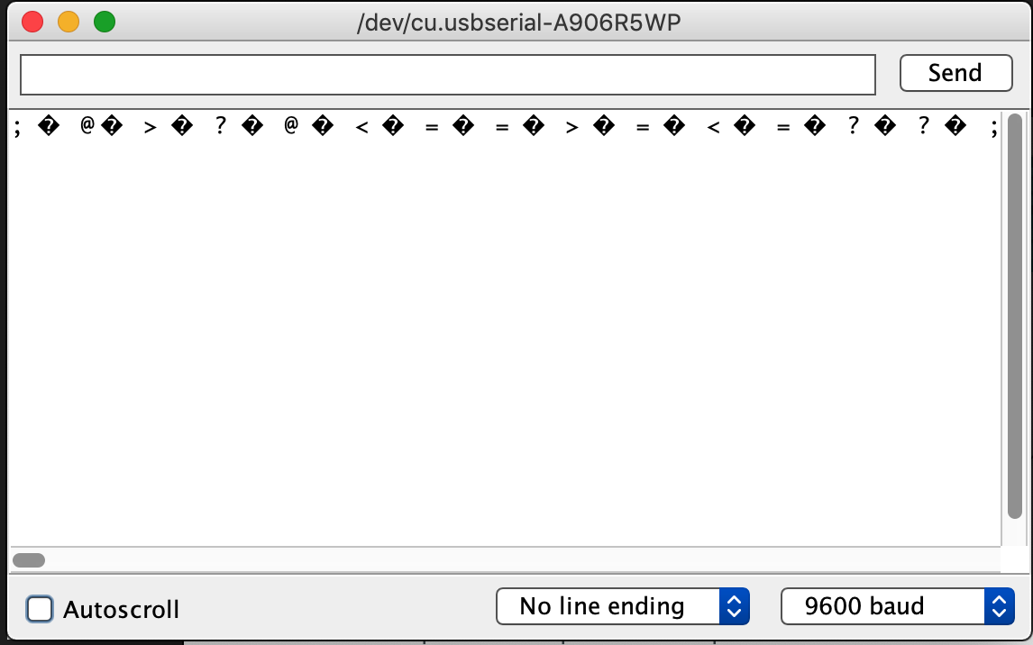
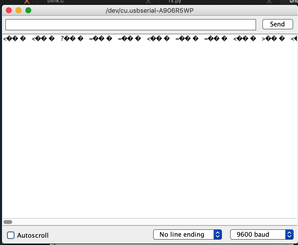
here’s a little proof.
Other notes:
general board in which you could connect multiple boards…
could work for thing with a single analog pin, but you’d have to consider what components/sensors need and how to make sure that exists on the board.
project would be to create breakout boards for each of the various pcbs so that we could easily plug and play different sensors.
Thank you Sam Calisch for answering questions about using the accelerometer!
IC2 actually refers to a voltage regulator that lowers the 5V incoming VCC to 3.3V because the accelerometer is only spec’ed to support 3.3V
The accelerometer is also the kind that is used in cell phones and already contains the logic for communicating a digital value rather than an analog one that will convert to a digital value. I2C communication requires 2 pins one for SDA (data) and one for SCL (clock)
I2C is “a synchronous, multi-master, multi-slave, packet switched, single-ended, serial computer bus invented in 1982 by Philips Semiconductor (now NXP Semiconductors). It is widely used for attaching lower-speed peripheral ICs to processors and microcontrollers in short-distance, intra-board communication. Alternatively I²C is spelled I2C (pronounced I-two-C) or IIC (pronounced I-I-C).” (Wikipedia)
Other notes from the office hours:
the resonator is useful for if you want to operate at a higher baud rate. Like 156200(?) rather than 9600
learning about step response; the idea is still that you’re still trying to measure capacitance. What you’re being creative about is what the plates are and what the dielectric behind the plates is. you could be the dielectric. the process of actually measuring a step response is 1) send a charge the the first plate and after some short period of time, check the voltage on the other plate. The second plate should charge exponentially (yes there is some equation specified to model this). If there’s a high voltage, that implies a high capacitance. If there’s a low voltage, that implies a low capacitance.