Kenny Friedman, Week 10
Output Week
Rotational Motion
This week, the goal was to create an output device.
Because I need rotational motion in my final project, and a motor is the obvious choice, it makes sense to get that up and working for output week. I had to decide between the big three main categories: DC motors, servos, and stepper motors.
The details of how each one works (links: DC, servo, stepper) are really fascinating but less important in the decision making process than what they can do.
I don't care about efficiency, but I need high precision. DC Motor can be ruled out right away. Between a servo and stepper motor, I think there are arguments to both sides. But I am going to use a stepper motor because the high-torque functionality of a servo is not necessary for my projects, and I don't need to worry about speed. Time to learn more about stepper motors.
Stepper Motor
First things first: I needed to aquire a stepper motor, figure out how they worked, figure out what kind I had, and how best to wire it up.
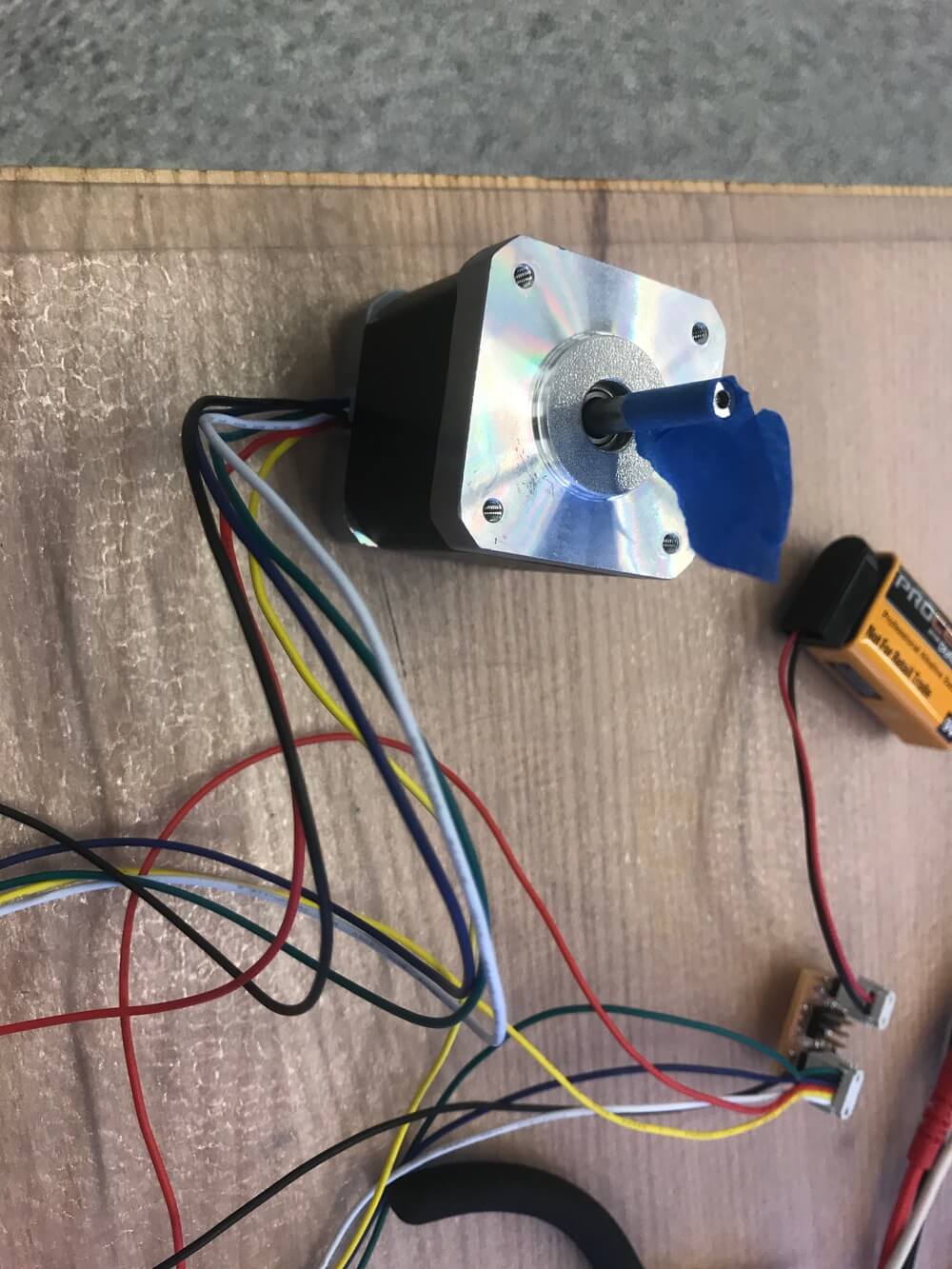
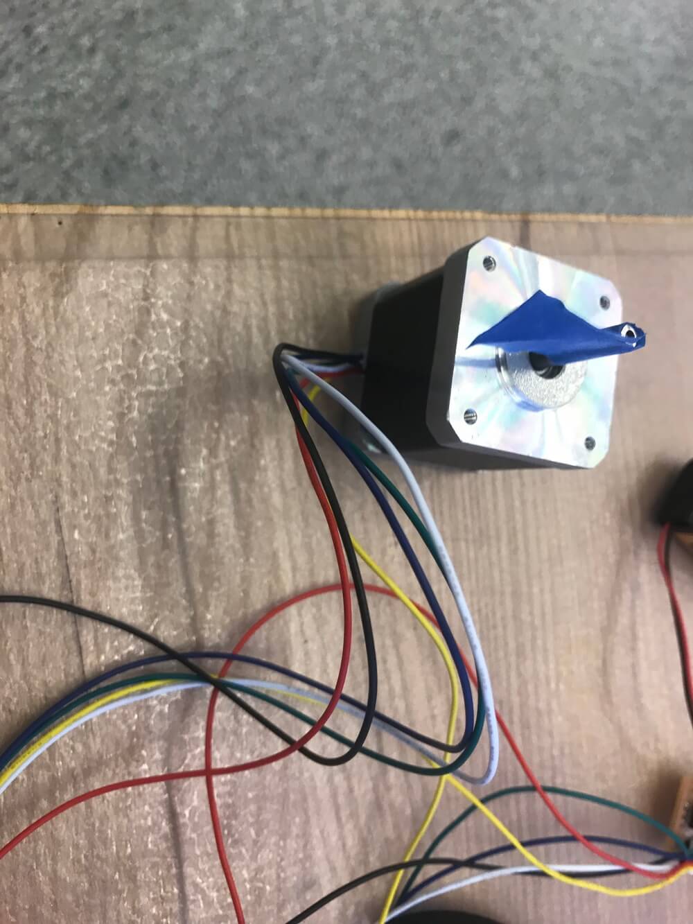
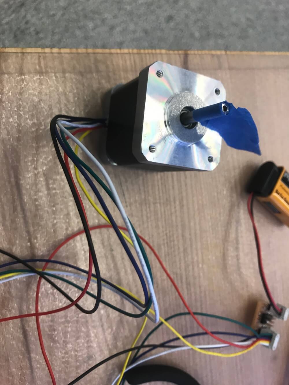
The Fab Inventory had a Jameco ReliaPro 238538, so I used that.
I found out that there are two main types of stepper motors: unipolar and bipolar. I learned the difference between unipolar and bipolar steppar motor (link: Bipolar Stepper Motors). It turns out that the Jameco in stock is a unipolar motor.
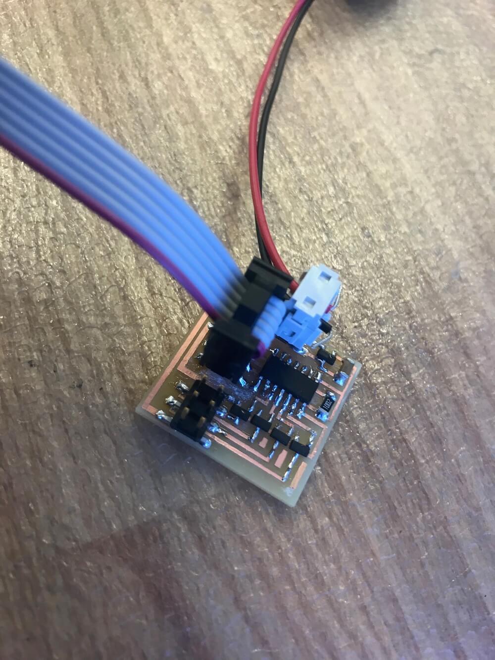
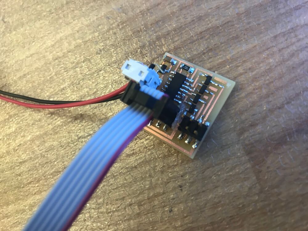
Stepper Motor Driver Board
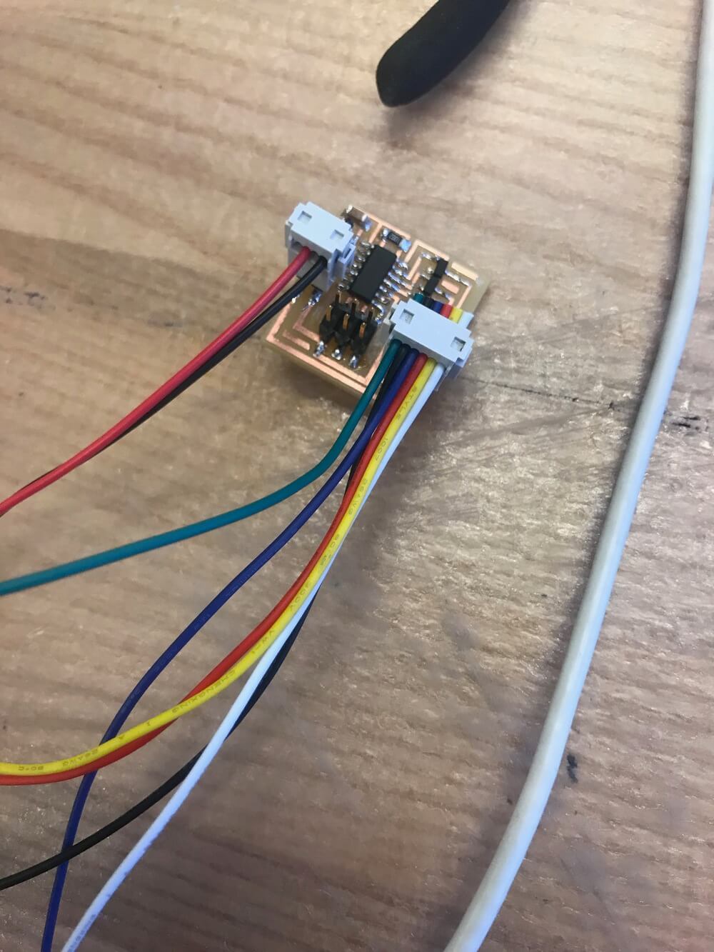
I used Neil's stepper motor driver board. I was considering using an IC driver, but since this is Fab class, I decided it makes sense to actually fab it myself.
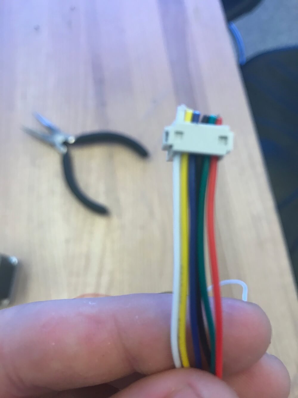
There was only one big trick: the wiring diagram on the board has different color wire labels than the stepper motor actually had. with some trial and error, I figured out the best way to do it. The correct color combination — from left to right — is: white, yellow, blue, green, and red.
I didn't get that color combination on the first try, it took some multimeter probing and some guess and checking.
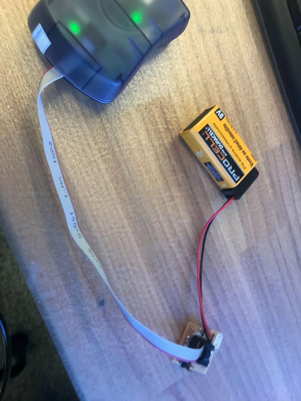
Photos