Using the 3D Scanner and Printer
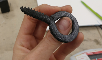
3D printing is an accessible way to build practical tools and components as well as fun figurines and sculptures. I really enjoyed seeing models of prosthetic joints, structural models, and realistic faces. I know that I'll be playing with this tool throughout the semester - it's fun to be able to model and create without needing to actualize an idea in CAD first. 3D printing - something I've always imagined as a tool of the future. I scanned a 3/8" eye screw that I had grabbed from the bike shop I work at. I was curious about how threaded hardware would come out on the printer - whether the grain of the plastic would prevent functional threading. The eye screw is not meant to thread into a bolt; it is normally driven straight into a drilled hole in wood or drywall. I was hoping to get a qualitative sense of how well the threads would work. Maybe after 2 or 3 prints I'd want to try a male-female threaded piece like a nut and bolt.
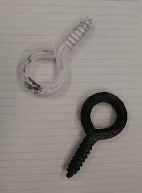
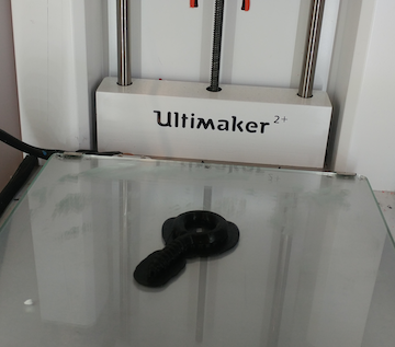
The Sense 3D scanner in the science center fab lab had trouble "tracking" pretty much anything I held up to it - not sure whether this might have been my unsteady hand or a distracting background. Luckily, a member of our section who works in the history department brought along the department's archival-quality scanner for class use. Because the scanner is easily confused by shiny metals, we covered the screw in white spray chalk before scanning. We made a 3D scan of the screw and (mostly) smoothed out the rough edges of the scan - the only visible imperfection was a toothy edge where the threads of the scans didn't quite match up. This would definitely stop the screw from threading into any type of nut. However, the scan otherwise looked pretty good. The scan help up well in CURA, the design software feeding the Ultimaker. Dixon helped me navigate the default suggested supports. I ended up wishing we had picked sparser supports - I had a bit of trouble prying them all off and needed a screwdriver. I printed the eye bolt in black PLA and it was finished in about half an hour. Here is a photo comparing this print to the original:
To avoid difficulties in scanning I think a logical next step would be designing a screw in Rhino and printing directly from the CAD file. This would definitely eliminate the nasty overlap on the edge of this printed screw. A better scan would also probably alleviate the nasty result of one bad scan, but it's definitely worth investing in learning how to model components for larger projects.